Investigating the sulfonated ZnO–PVA membrane for improved MFC performance
-
Ravi Jenani


Abstract
In the era of climate change and the global energy crisis, alternate energy sources are desirable to replace carbon and fossil fuels. Microbial fuel cells (MFCs) are distinctive because of their ability to transform organic waste into electricity through bio-electrochemical reactions. The current study investigates the preparation and application of zinc oxide nanoparticles (ZnO NPs) and sulfonated ZnO nanoparticles (SZnO NPs) incorporated in polyvinyl alcohol (PVA) membrane as a separator in dual-chambered MFC for Tannery wastewater treatment. Characterization of these membranes shows that the NPs are well dispersed onto the polymer base. The synthesized sulfonated membrane has better water uptake capacity (90.5%) and oxygen mass transfer coefficient (1.09 × 10⁻⁶ cm·s−1) than the Nafion membrane water uptake capacity (21.8%) and oxygen mass transfer coefficient (2.68 × 10⁻⁴ cm·s−1). Different amounts of NPs were incorporated into the polymer base to optimize the membrane performance by increasing the proton conductivity for better operation in MFC with reduced biofouling. When the MFC was operated with tannery wastewater, a maximum power density of 160.554 mW·m−2 and a chemical oxygen demand removal of 84.618% were obtained using the PVA–SZnO membrane with reduced biofouling. This observation proves that the sustainable and affordable PVA–SZnO membrane can be used as a separator for MFC and for treating Tannery wastewater.
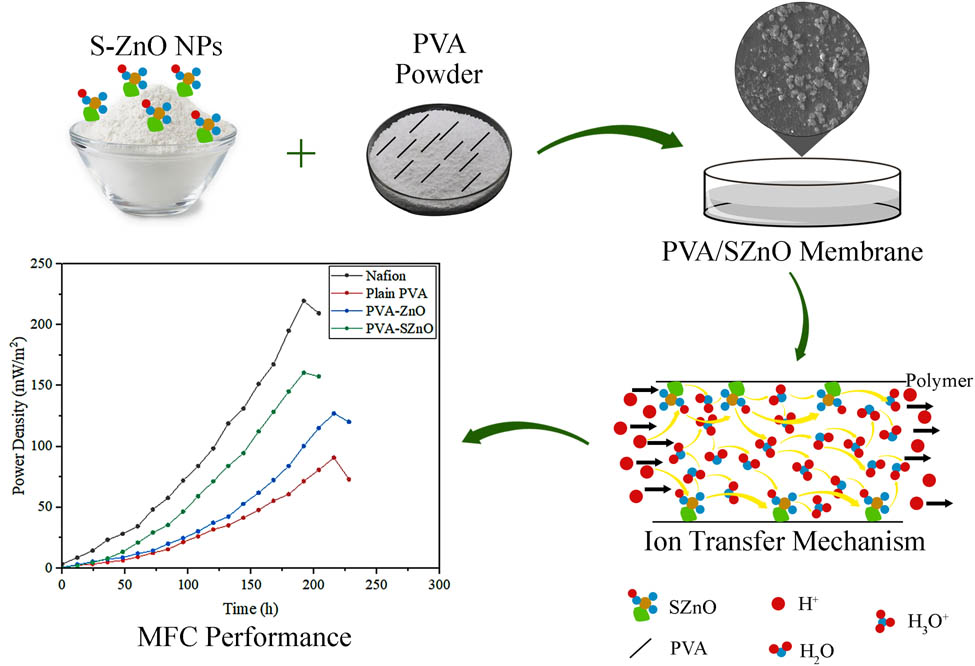
Graphical abstract
1 Introduction
Water is an invaluable resource on Earth, and its scarcity is one of the most pressing issues in the world today [1]. Uncontrolled population growth, resulting in vast industrialization, urbanization, and agricultural activities, generates around 359.4 × 10⁹ m3 of wastewater yearly [2]. In addition, it has been anticipated that by 2040, world energy consumption will rise to 56% [3]. This will end up with an overburden of water and energy demand. Sustainable energy generation and wastewater treatment technologies have arisen to combat this severe issue in recent years. Among the newer technologies that have emerged, the microbial fuel cell (MFC) is found to be the most promising one.
MFC is a revolutionary green energy conversion technique that employs catalysis to transform chemical energy into electrical energy. MFCs are additionally utilized in biological restoration, including the treatment of organic contaminants in wastewater [4], soil remediation [5], eliminating the presence of heavy metals in wastewater [6], and assessing the integrity of water [7]. Therefore, MFCs have been receiving greater prominence for their biological and electrochemical properties [8]. MFCs are still far from their ideal performance due to limitations like short life spans, minimal production rates [9], membrane fouling [10], high expenditures [11,12], and limited efficiency enhancements. Numerous factors influence MFC operation, thereby severely restricting its commercial applications, such as electrode material, temperature, pH, biofilm, substrate loading rate, and external resistance; however, optimizing the membrane exhibits significant advancement in the system [13].
MFC’s functioning is less effective without a membrane due to increased substrate and oxygen diffusion [14]. Furthermore, the tight packing of electrodes in such membrane-less MFCs amplifies the potential for short circuits [15,16]. Moreover, even if the proton exchange membranes (PEMs) were removed from the membrane-less form, the internal resistance increases [17,18]. Therefore, membranes are crucial for dual-chambered MFCs to function effectively and to avoid adverse crossover that would increase the open-circuit voltage value [19]. An ideal PEM must exhibit a hydrophilic nature for low resistance and be neutral to prevent pH change and ion selectivity. Also, an ideal PEM is mechanically robust to resist any deformation and has anti-biofouling properties to enable steady power generation for an extended period [20].
A variety of membrane materials were researched and employed as separators in MFC systems. A few of the most popular commercial membrane materials are Nafion, Ultrex, and Zirfon. Among them, the widely utilized membrane is Nafion, engineered by Nafion DuPont Inc., USA, primarily because of its accessibility and acceptable performance. The primary downsides of Nafion materials are their high price tag, oxygen leakage, substrate loss, and biofouling. Further commercial membranes are also being deployed in MFCs, some of which are Nafion AMPS-MMT [21], Zirfon [22], Clayware-20% MT-alkali [23], TiO2/SiO2, nanoscale polypyrrole [24], and SBC-600 [25].
Recently, polyvinyl alcohol (PVA)-based polymer membranes have garnered a lot of interest for their wide range of applications in the medical industry, fuel cells, and other fields. PVA is a biodegradable, non-toxic, and economically viable polymer [26]. Following its innate hydrophilicity, it is appropriate for wastewater treatment. To enhance the potency of the PEM, zinc oxide nanoparticles (ZnO NPs) were infused into the PVA polymer. ZnO is potentially ideal material for research due to its affordable production costs, facile availability, lesser toxicity, and physical characteristics that permit a variety of technical applications [27]. ZnO/PVA-based composite membranes have a huge scope due to their peculiar structural and functional characteristics, which exhibit tremendous potential in a range of electrical, optical, and water treatment applications [28]. ZnO has been demonstrated to have a larger surface area, which facilitates better water uptake, thereby promoting vehicular mechanisms that enable ion transfers. Additionally, ZnO NPs are reported to exhibit antimicrobial qualities [29,30]. Furthermore, sulfonation of ZnO (S-ZnO) is carried out to promote proton conductivity using the Grotthuss technique in addition to vehicular mechanisms. The mechanical integrity and anti-biofouling properties of the composite membrane are additionally enhanced by the introduction of S-ZnO [31].
Henceforth, this is a novel approach for integrating green-synthesized ZnO NPs into a PVA polymer membrane using the solvent evaporation method to enhance the PEM’s potency by improving its mechanical strength, thermal stability, antimicrobial properties, and proton conductivity to study its application in MFCs using tannery wastewater. The most significant advantage of this work is that it is cost-effective, biodegradable, and ecologically benign, and it can potentially be used on a large scale without endangering the ecosystem.
2 Materials and methods
2.1 Preparation of ZnO NPs and sulfonated ZnO (S-ZnO) NPs
For the preparation of ZnO NPs via green synthesis, Ixora coccinea, Hibiscus rosa-sinensis, and Sphagneticola trilobata leaves were gathered in and around the premises of the Vellore Institute of Technology (Katpadi, Vellore, India). Fresh leaves were thoroughly cleaned and air-dried at room temperature and finely chopped into small pieces. To prepare the aqueous extract solution, 10 g of each chopped leaf was separately boiled with 100 cm3 of distilled water at 60°C for about 20 min until the color of the aqueous solution changed to a light brown and filtered after cooling to normal temperature. A total of 10 mL of each aqueous leaf extract was taken in a conical flash separately. To each, a 50 cm3 of 0.5 M zinc acetate dihydrate solution was introduced after 10 min of stirring in a magnetic stirrer at 6,000 rpm. Sodium hydroxide (2 M) was added to each of the leaf extract solutions to maintain the pH value, which thereby produced a pale white aqueous solution when stirred for 2 h. These solutions were then ultrasonicated for 1 h to minimize the particle size and centrifuged at 6,000 rpm twice for 10 min. The centrifuged particles were dried for 6 h at 60°C in a hot air oven, followed by 3 h of calcination in a muffle furnace [32]. A pale-colored powder of ZnO NPs was finally obtained.
The S-ZnO NPs were prepared with concentrated sulfuric acid. About 1 g of acquired ZnO NPs were suspended in 20 mL of methanol, and 7.5 mL of 0.5 M concentrated H₂SO₄ and kept in the ultrasonicator for 1 h. The solution was centrifuged with methanol 4–5 times after the sulfonation reaction was completed. The resulting solution was then transferred to the Petri plate and heated to 60°C for 2 h under vacuum [33]. The S-ZnO NPs obtained were utilized for further investigation and experiment.
2.2 Fabrication of membranes
Three distinct types of membranes (PVA, ZnO-doped PVA, S-ZnO-doped PVA) were synthesized using the solvent evaporation technique. The performance of membranes was analyzed by considering various parameters, such as water uptake capacity, proton conductivity, ion exchange capacity (IEC), oxygen mass transfer coefficient, and oxygen diffusion coefficient. The most efficacious and functional membrane was selected for the experiment.
For the preparation of the various quantities (8, 10, 12, and 14% wt basis) of PVA membrane, PVA powder was dissolved in water and kept in the ultrasonicator for 1 h. The resultant mixtures were then kept in the magnetic stirrer for 12 h at 60°C and again kept in the sonicator for an hour. The solution was then transferred into a Petri dish and heated to 60°C for 6 h. The membranes were then submerged in a 10% H2O2 solution for 1 h and then in a 10% H2SO4 solution for 12 h before being detached from the Petri plate, which was then used for the rest of the experiment processes [34].
For the preparation of ZnO-doped PVA and S-ZnO-doped PVA membranes, 40 mL of deionized water was mixed with the prepared ZnO NPs and S-ZnO NPs and placed in an ultrasonicator for 1 h. The mixture was then combined with the required amount of PVA powder and stirred in a magnetic stirrer at 60°C for 12 h, followed by sonication for 1 h [35]. The solution was then poured into the Petri dishes and heated to 60°C for 6 h. The resultant solution was then immersed in a 10% H2O2 solution for an hour, followed by a 10% H2SO4 solution for 12 h to produce the desired membrane [34]. The entire process is summarized and presented in Figure 1.
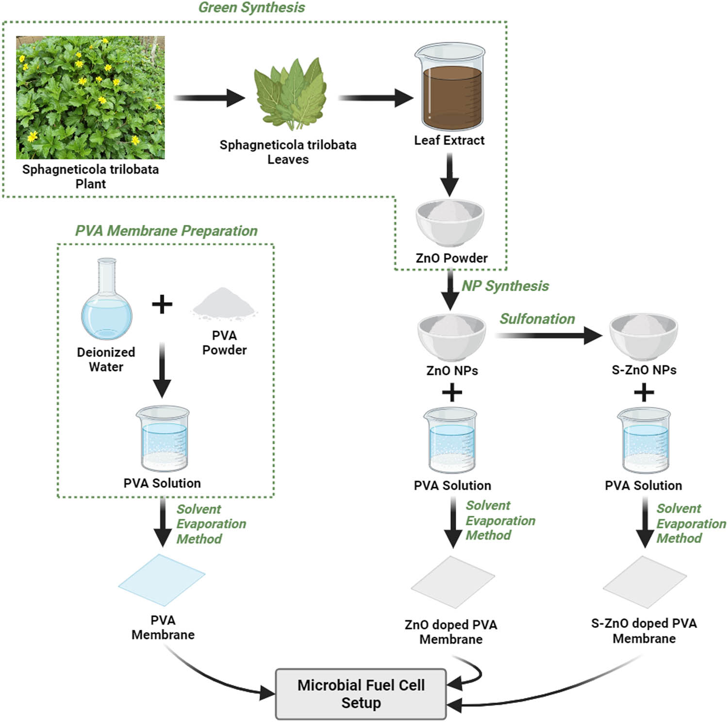
Graphical representation of fabrication of NPs and membrane.
2.3 MFC construction and operation
Cylindrical-type dual-chambered MFC with open-air cathode assembly was used for the experiment with a working volume of 500 mL on each side. A graphite plate was used as the electrode for both the anode and cathode chamber, which were spaced 1 cm apart. The cathode electrode was exposed to air, and continuous air was supplied using an aquarium pump. Tannery wastewater collected from nearby industries was used as the anode source, and the cow ordure was used as the bacterial inoculum. All the experiments were carried out in batch mode with a neutral initial pH and room temperature. An external resistance of 1,800 Ω was employed and maintained. PVA, PVA-ZnO, and PVA-S-ZnO membranes with different PVA amounts were used for the experiment for comparative analysis. The chemical oxygen demand (COD) of the tannery wastewater was measured using the closed reflux titrimetric method. Aliquot samples were taken from the MFC within 48 h of the interval and tested for COD measurements. The pH of the solution was measured by using a pH meter (Systronics MK-VI). Voltage and current output from MFCs were noted continuously.
2.4 Membrane analysis and MFC electrochemical evaluation
The water uptake capacity of the membrane was calculated by the difference in weight of the membrane after submerging the membrane in water for a day. The IEC of the membrane was calculated by using titrimetric analysis. The oxygen diffusion coefficient was determined by using the DO probe to measure the oxygen transfer from one chamber to another chamber. The proton conductivity of the membrane was analyzed by electrochemical impedance spectroscopy in the range of 102–10−3 Hz [36]. The surface morphology of the membrane loaded with ZnO nanoparticles was studied using scanning electron microscopy (SEM), X-ray diffraction (XRD), and Fourier transform infrared spectrophotometry (FTIR) methods.
A digital multimeter with an external resistance of 1,800 Ω was used to measure the voltage of the system. The current, power density and current density were calculated using Eqs. (1)–(3). The COD removal, coulombic efficiency (CE), and normalized energy recovery (NERv) values were also calculated using Eqs. (4)–(6) [37]:
3 Results and discussion
3.1 Optical, structural, and surface morphology analysis of NPs
The synthesized ZnO NPs were examined using UV spectrophotometry, which revealed that the maximum absorption peak for ZnO NPs synthesized using Ixora coccinea was recorded at 327 nm, Hibiscus rosa-sinensis at 324 nm, and Sphagneticola trilobata at 320 nm, further confirming the formation of ZnO NPs. These results are consistent with the standard ZnO absorption pattern because all oxide materials have large band gaps and shorter wavelengths. The amounts of ZnO NPs obtained from Ixora coccinea, Hibiscus rosa-sinensis, and Sphagneticola trilobata were 1.83, 2.17, and 2.46 g respectively.
The XRD of ZnO NPs generated from different plant sources can be observed in Figure S1. With the presence of (100), (002), (101), (102), (110), (103), (200), (112), (201), (004), (202), (104), and (203), it was found that the crystalline structure of ZnO NPs matches the standard JCPDS 036-1451. Sulfonation was carried out on the ZnO NPs obtained from Sphagneticola trilobata because it yields the greatest amount of ZnO. The XRD of ZnO and SZnO obtained from Sphagneticola trilobata is displayed in Figure 2 for comparison. The addition of sulfonic groups to the NPs may be the reason for the observed modest shift in the peak and a small decrease in the intensity in S-ZnO [33]. The average crystalline size of the NPs obtained from the Sphagneticola trilobata leaf extract was calculated using the Scherrer equation, Williamson–Hall (W-H) plot, and the size strain plot (SSP). Table 1 provides the summarized results obtained from the Scherrer method, W-H plot, and SSP models.
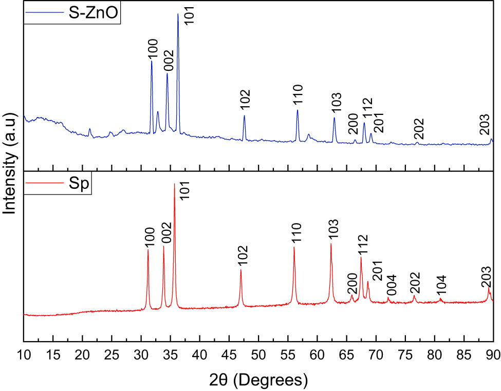
XRD patterns of the ZnO NPs and SznO NPs obtained from Sphagneticola trilobata.
Geometric parameters of ZnO and S-ZnO NPs
| NPs | Scherrer method | W-H method | SSP method | ||
|---|---|---|---|---|---|
| Diameter D (nm) | Diameter D (nm) | Microstrain ε (units ×10−3) | Diameter D (nm) | Microstrain ε (units ×10−2) | |
| ZnO | 56.5551 | 57.2396 | 2.78 | 53.0463 | 1.6975 |
| SZnO | 38.24452 | 40.5648 | 2.13 | 36.56979 | 1.4237 |
The crystalline sizes of the ZnO NPs and SznO NPs were calculated using the Scherrer equation [38] (Eq. (7)):
where k is the shape factor (1.5406), λ is the X-ray wavelength (nm), β is the full width at half-maximum (FWHM) from the XRD pattern (rad), and θ is the degree from half of 2θ in the X-axis of the XRD pattern.
The Scherrer equation has a 1/cos θ dependency but not tan θ as in the W-H method. The fundamental distinction is that the microstructure causes small crystallite size, and microstrain occurs together from reflection broadening. The separation of size and strain broadening analysis is carried out using Williamson and Hall, as shown in Eq. (8), depending on the different θ positions [39].
where K represents the shape factor (0.94), λ is the X-ray wavelength (Å), β is the FWHM from the XRD pattern (rad), θ is the degree from half of 2θ in the X-axis of the XRD pattern, D is the crystallite size (nm), and ε is the microstrain.
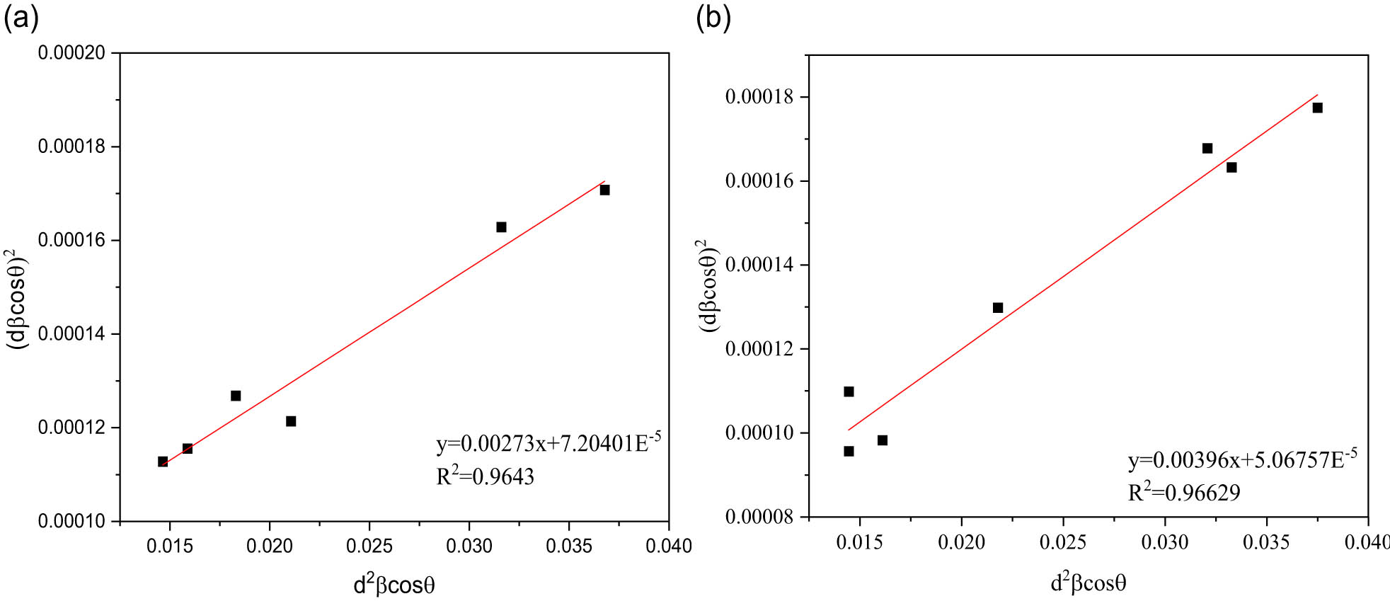
The uniform distribution method is represented by Eq. (8), which assumes that the strain is consistent across all crystallographic directions. For the peaks of ZnO and SZnO, β cosθ was plotted with 4 sin θ. The slope and y-intercept of the fitted line are used to calculate the strain and particle size, respectively [39].
The diameter (D) obtained is in the range of nanometers, and the strain value obtained is positive, which indicates the tensile type of strain induced in the crystal lattice [40]. The analysis results are shown in Figure 3.
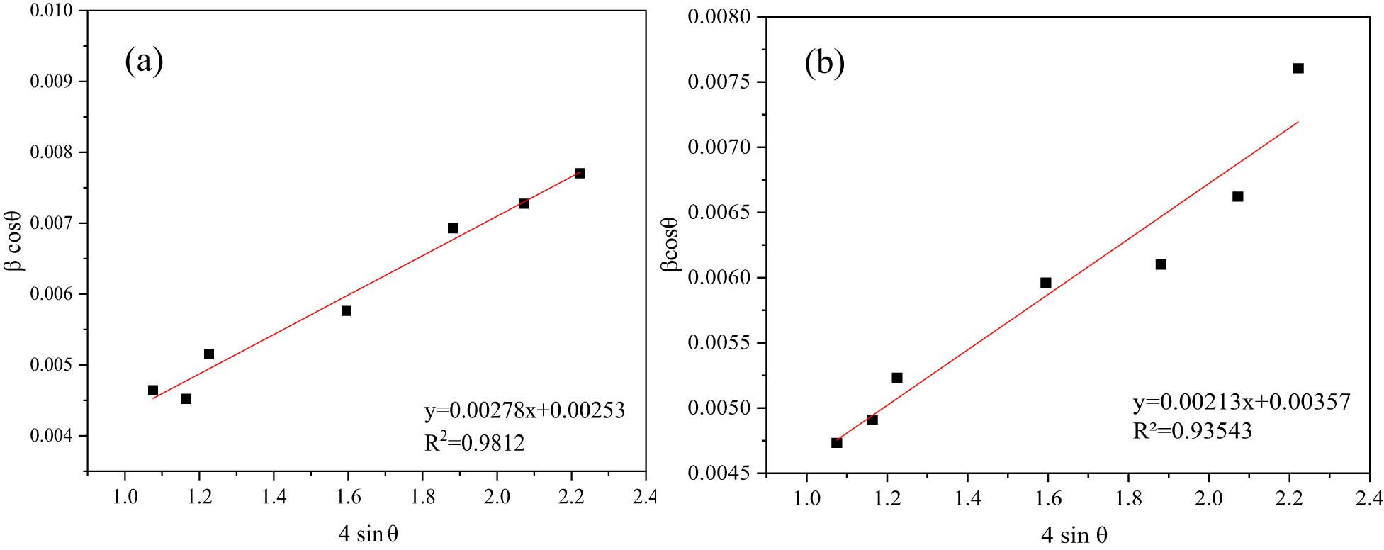
Williamson–Hall method analysis of (a) ZnO NPs and (b) SZnO NPs.
The “size–strain plot” (SSP) can be used to determine the size–strain parameters and study the isotropic behavior. This has the advantage of obtaining data from high-angle reflections with less significance given to the results. The “strain profile” is represented by a Gaussian function in this calculation, and the “crystallite size” is represented by a Lorentzian function, as shown in Eq. (9) [40]:
where k is the shape factor (0.94), λ is the X-ray wavelength (Å), β is the FWHM from the XRD pattern (rad), θ is the degree from half of 2θ in the X-axis of the XRD pattern, D is the crystallite size (nm), ε is the microstrain, and d is the distance between atomic layers in a crystal.
For the peaks of ZnO and SZnO,
SSP method analysis of (a) ZnO NPs and (b) SZnO NPs.
The FTIR spectra of ZnO NPs from different plant sources are shown in Figure S2. As shown in the figure, the transmittance peak at 2,278 cm−1 represents the C–C groups, the N–H peaks are represented by peaks near 1,613 and 1,567 cm−1, and the C–C groups are represented by vibrations at 1,430 cm−1 and a deep peak at 1,017 cm−1. Numerous stretches that correspond to the C–H groups can be detected close to the 880–550 cm−1 range. At 1,502 cm−1, the N–O bonds are represented by a single peak. The lack of peaks in the 3,500 and 2,500 cm−1 range suggests that plant sources do not exhibit the typical OH and N–H stretching. The FTIR spectra of ZnO and S-ZnO, obtained with Sphagneticola trilobata, are shown in Figure 5. The peaks at 1,140 and 1,082 cm−1 indicate the sulfonates and sulfates ion groups in NPs, which denote successful sulfonation. The peaks in the range of 683–400 cm−1 represent ZnO compounds.
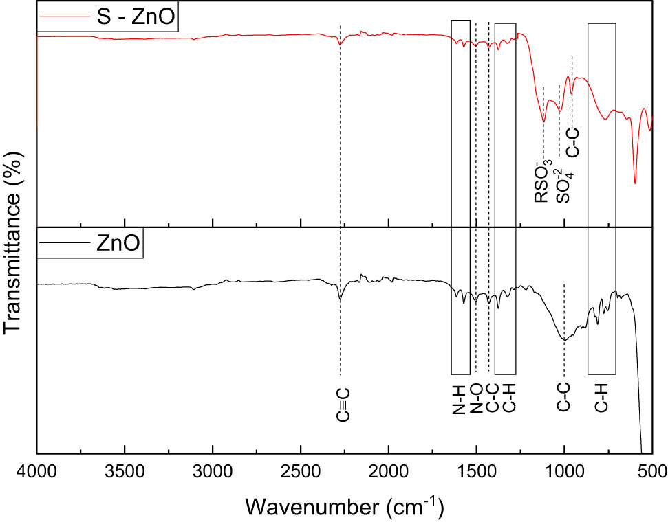
FTIR spectra of ZnO NPs and SZnO NPs obtained from Sphagneticola trilobata.
SEM analysis was carried out for the determination of the surface morphology of the NPs. The SEM image for the NPs prepared from various plant sources is shown in Figure S3. The SEM images of ZnO and SZnO NPs from Sphagneticola trilobata are shown in Figure 6(a) and (b), which indicates that the NPs are spherical, complex with distinct grain boundaries, and are in the form of small clusters loosely agglomerated. The residues of proteins and amino acids are Carbonyl and NH groups. These can bind to metals by developing a coating around the metal to prevent agglomeration and help stabilize the NPs [41]. The EDX shows that the ZnO obtained is almost pure, with 48.91% of zinc. Upon sulfonation, the shape of clusters increased with a slight change in the shape with a more structured boundary. The efficiencies of the developed membranes were compared with the commercially available Nafion membrane.
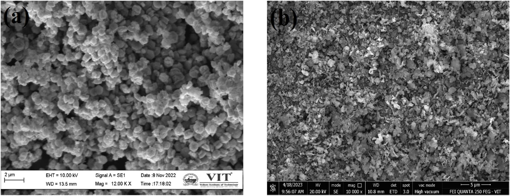
Surface morphology of Sphagneticola trilobata: (a) ZnO NPs and (b) SZnO NPs.
Zeta potential analysis was done for the prepared NPs and is shown in Figure 7. As shown in the figure, the ZnO NPs have a zeta potential of −25.6 mV. This proves that the ZnO NPs are highly stable and have an electrostatic repulsion, which avoids the agglomeration of NPs, and the biomolecules present in the biosynthesized ZnO NPs are positively charged groups [42].
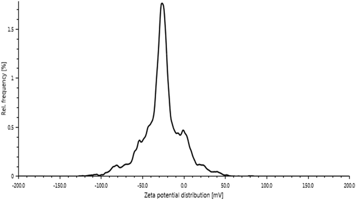
Zeta potentials of ZnO NPs from Sphagneticola trilobata.
3.2 Characterization of Nafion and the prepared membranes
The XRD profile of the PVA membrane prepared with different concentrations is shown in Figure S4, and PVA with varying weight percentages of ZnO and SZnO is displayed in Figure 8(a) and (b). A large peak at 19.5° and a small peak at 40.5° indicate the presence of PVA [43]. When ZnO and SZnO were added to the polymer backbone, the PVA peak decreased, which may be due to the formed NPs. The FTIR spectra of PVA and PVA with 0.35 g of ZnO and SZnO are displayed in Figure 9. A spectrum at 3,290 cm−1 indicates the presence of OH, which was absent in ZnO and was seen in the PVA peak. The peak at 2,921 cm−1 indicates the CH2 group, which corresponds to the peaks obtained for PVA [44]. The FTIR spectra of PVA with different weight percentages of ZnO and SZnO are shown in Figure S5. The SEM images of the Nafion and the prepared membranes are shown in Figure 10. The Nafion membrane was a bit rough. When the PVA membrane was analyzed, it was found that the plain membrane was slightly rough with the absence of deformation [45]. Membranes with added NPs have white patches and clusters, which indicate the dispersion of NPs on the membrane surface. When large quantities of NPs were added, the NPs got agglomerated. The surface of all the membranes, even at the nanoscale, appeared smooth with no visible pores. Hence, the membranes can be classified as non-permeable, except for species like protons. The EDX shows the presence of carbon (56.52%) and oxygen (43.48%) in the plain PVA membrane. For the ZnO and SZnO inoculated membranes, zinc (8.46%) and sulfur (2.24%) were obtained with a slight change in carbon and oxygen.
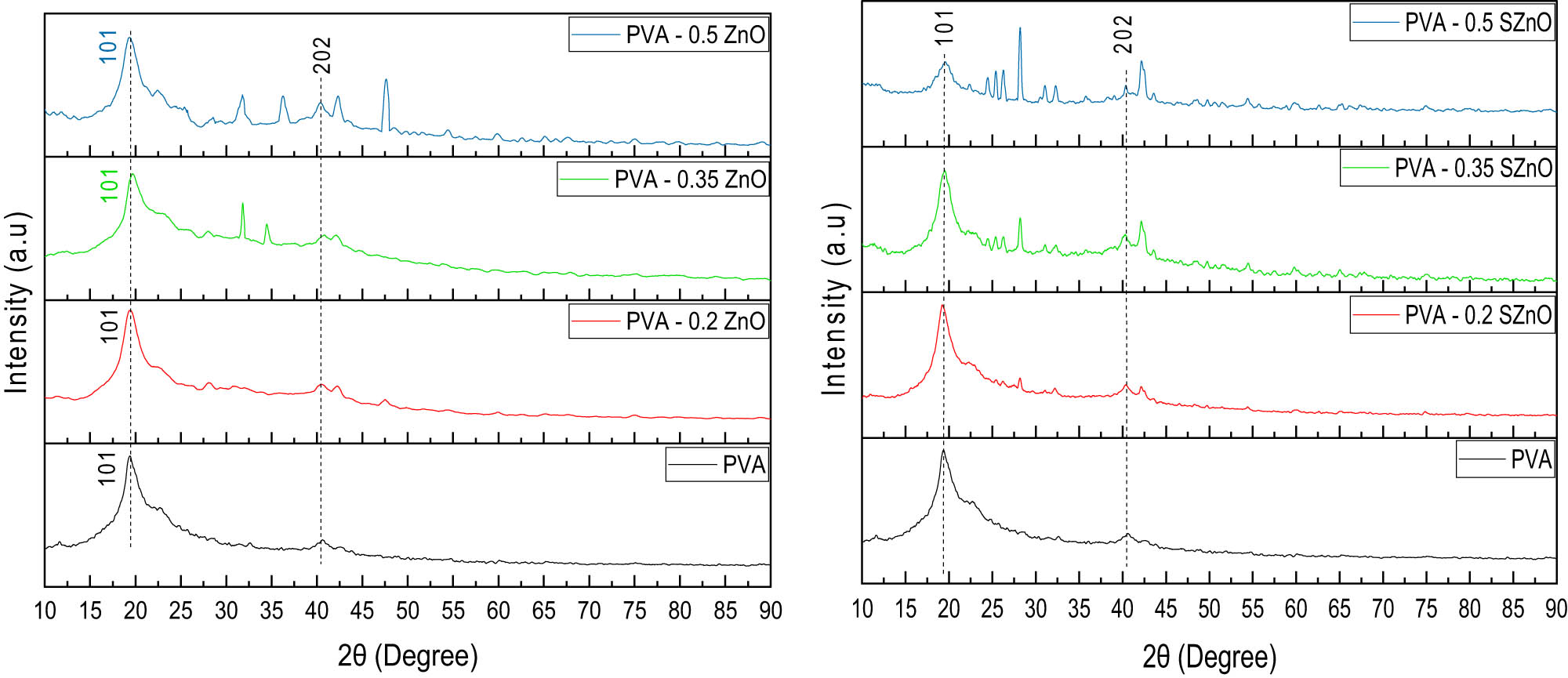
XRD pattern of the PVA membrane with (a) PVA-ZnO and (b) PVA-SZnO.
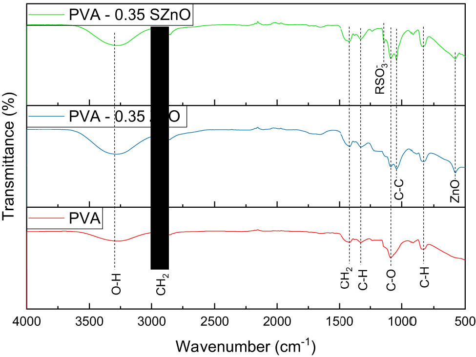
FTIR spectra of the PVA membrane with PVA-0.35 ZnO and PVA-0.35SZnO.
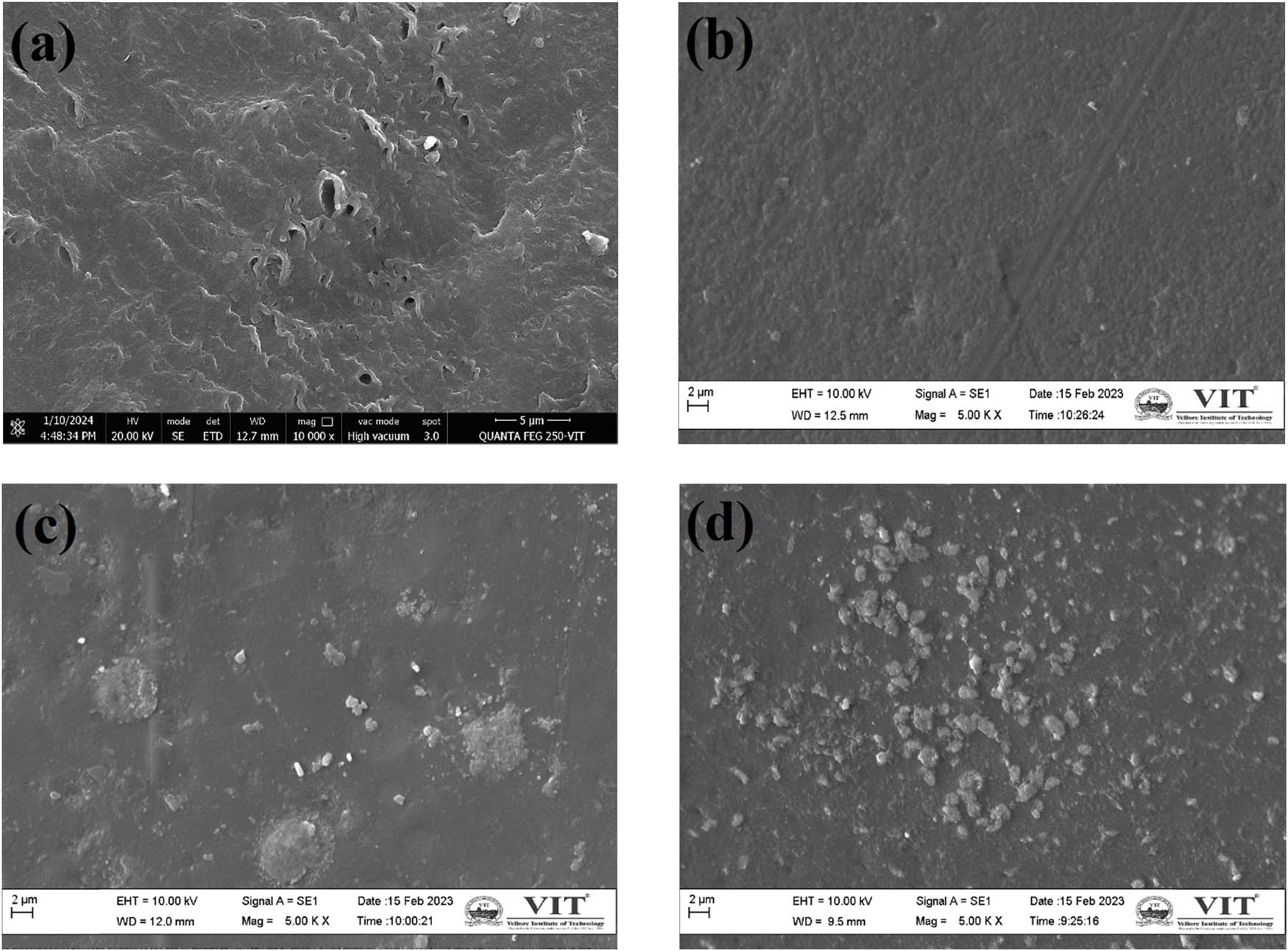
SEM image of membranes: (a) Nafion, (b) PVA, (c) PVA-0.35ZnO, and (d) PVA-0.35SZnO.
The water uptake capacity of each membrane was determined by soaking the membrane in distilled water for 24 h. Table 2 shows the water uptake capacity of all the prepared membranes. The graphical representation of the water uptake capacity is shown in Figure S6. Water uptake is crucial for ionic conductivity because proton (H⁺) transport in membranes primarily occurs as follows:
Vehicle mechanism: Protons move via solvated species (e.g., hydronium ions H3O⁺ in water).
Grotthuss mechanism: Protons “hop” between water molecules via hydrogen bonding [31].
Characterization of the synthesized nanocomposite membrane
| Membranes | Thickness (µm) | Water uptake capacity (%) | Proton conductivity (mS·cm−1) | IEC (meq·g−1) | Oxygen mass transfer coefficient, KO2 (cm·s−1) | Oxygen diffusion coefficient, DO2 (cm²·s−1) |
|---|---|---|---|---|---|---|
| Nafion | 188 | 21.8 | 81.1 | 0.87 | 2.689 × 10⁻⁴ | 5.055 × 10⁻⁶ |
| 8% PVA | 195 | 152.2 | 7.8 | 0.25 | 2.28 × 10⁻⁶ | 4.446 × 10⁻⁸ |
| 10% PVA | 195 | 141.2 | 8.9 | 0.29 | 1.92 × 10⁻⁶ | 3.744 × 10⁻⁸ |
| 12% PVA | 190 | 99.4 | 11.2 | 0.31 | 1.65 × 10⁻⁶ | 3.135 × 10⁻⁸ |
| 14% PVA | 190 | 81.3 | 15.2 | 0.3 | 1.83 × 10⁻⁶ | 3.477 × 10⁻⁸ |
| 10% PVA–0.2 ZnO | 196 | 59.9 | 13.5 | 0.34 | 1.88 × 10⁻⁶ | 3.685 × 10⁻⁸ |
| 10% PVA–0.35 ZnO | 195 | 54 | 16.7 | 0.45 | 1.69 × 10⁻⁶ | 3.296 × 10⁻⁸ |
| 10% PVA–0.5 ZnO | 192 | 44.7 | 14.3 | 0.39 | 1.58 × 10⁻⁶ | 3.034 × 10⁻⁸ |
| 12% PVA–0.2 ZnO | 195 | 82.6 | 24.6 | 0.49 | 1.52 × 10⁻⁶ | 2.964 × 10⁻⁸ |
| 12% PVA–0.35 ZnO | 205 | 78.3 | 26.8 | 0.57 | 1.47 × 10⁻⁶ | 3.014 × 10⁻⁸ |
| 12% PVA–0.5 ZnO | 200 | 66.6 | 23.3 | 0.52 | 1.38 × 10⁻⁶ | 2.76 × 10⁻⁸ |
| 12% PVA–0.2SZnO | 210 | 95.1 | 37.8 | 0.67 | 1.13 × 10⁻⁶ | 2.373 × 10⁻⁸ |
| 12% PVA–0.35SZnO | 209 | 90.5 | 39.6 | 0.73 | 1.09 × 10⁻⁶ | 2.278 × 10⁻⁸ |
| 12% PVA–0.5S-ZnO | 212 | 87.6 | 37.1 | 0.69 | 1.11 × 10⁻⁶ | 2.35 × 10⁻⁸ |
Sulfonated membranes have increased hydrophilic sulfonic acid (−SO3) groups in the membrane structure along with the regular –OH groups present in the NP-incorporated polymeric groups, which help in the attraction of water molecules, thereby forming a hydrated membrane with a higher water uptake capacity. Higher water uptake leads to more proton-conducting pathways, which in turn increases the performance of the MFC [33]. It was found that the Nafion membrane has a water uptake capacity of 21.8%, whereas the PVA membrane has a higher capacity of 152.2%. When the ZnO NPs were embedded in the membrane, the capacity decreased to 78.3%, and the SZnO NP-induced membrane had a slightly greater capacity of 90.5%. Increased water uptake leads to the Grotthuss mechanism, which attracts the available H+ ions from the anionic region to the cationic region [46].
The proton conductivities of the membranes were measured and are tabulated in Table 2. From the results, it is seen that the Nafion membrane has a great proton conductivity of about 81.1 mS·cm−1. PVA membrane has a very low proton conductivity of 7.8–15.2 mS·cm−1. When it was incorporated with ZnO and SZnO, the proton conductivity increased from 26.8 and 39.6 mS·cm−1, respectively. This increase could be because of the increased surface area created by the addition of NPs, which resulted in increased absorption of gas (H2 and O2) from the membrane on both the anode and cathode sides [44]. The graphical representation of the proton conductivity of the membrane is shown in Figure S7.
The IEC was measured by the titration method and the values are given in Table 2. The IEC of the Nafion was the highest among all the membranes at about 0.87 meq·g−1. The PVA membrane has very low IEC, but when ZnO was added to the polymer base, the IEC increased. It attained a maximum value when SZnO was added to the polymer of 0.73 meq·g−1, which was almost equal to the Nafion membrane. The increased IEC capacity could be because of the presence of the sulfone group, which attracts the proton [33]. The graphical representation of the IEC for all the membranes is shown in Figure S8. The thickness of all the membranes was measured and ranged from 188 to 212 µm, as shown in Table 2.
Another prime concern for the use of the Nafion membrane is its oxygen transfer rate. To facilitate the obtained electrons primarily for electricity generation, anaerobic conditions had to be maintained in the anode chamber. This can be ensured when the prepared membrane has a lower KO2 and DO2. The oxygen crossover was measured by using the MFC setup with the substrate devoid of the inoculum and previously treated with the N2 gas to remove the oxygen that was present in the setup. Using the DO probe, the oxygen buildup in the anode chamber was measured. The oxygen mass transfer coefficient (KO2) and oxygen diffusion coefficient (DO2) are calculated, and the obtained values are given in Table 2. The prepared membranes have a lower KO2 and DO2 than the Nafion membranes (2.689 × 10⁻⁴ cm·s−1 and 5.055 × 10⁻⁶ cm2·s−1, respectively). The lowest KO2 and DO2 were obtained for the PVA-SZnO with values of 1.09 × 10⁻⁶ cm·s−1 and 2.35 × 10⁻⁸ cm2·s−1, respectively, which preferably favors the anaerobic condition and forcing the electrons to travel to the cathode through the external circuit. When ZnO NPs were increased, an increase in KO2 (1.11 × 10⁻⁶ cm·s−1) and DO2 (2.35 × 10⁻⁸ cm²·s−1) were seen. The result trends are consistent with the previous reports [33,47].
The comparison of all the results shows that the PVA–0.35ZnO membrane and PVA–0.35 SZnO membrane provide better results. This membrane was further chosen for the MFC performance analysis and these membranes were also examined for the contact angle. The contact angles of all the membranes are shown in Figure 11. When the contact angle is less than 90°, the membrane formed is hydrophilic and all the prepared membranes fall in that range. The hydrophilic nature of the membrane can also comply with the results obtained for water uptake capacity. The Nafion membrane has a contact of 80.6°; hence, it has a lower water uptake capacity than other membranes. PVA has a low contact angle of 58.9° and, hence, higher water uptake capacity and this perfectly matches with the established PVA contact angle of 57–77° [45]. When the amount of ZnO NPs increased, the hydrophilicity of the membrane decreased, which led to lower water uptake, which again led to reduced proton transfer. A higher amount of ZnO also leads to the blockage of the ionic pathway and hinders the performance of the microbes, which affects the performance of the MFC [33].
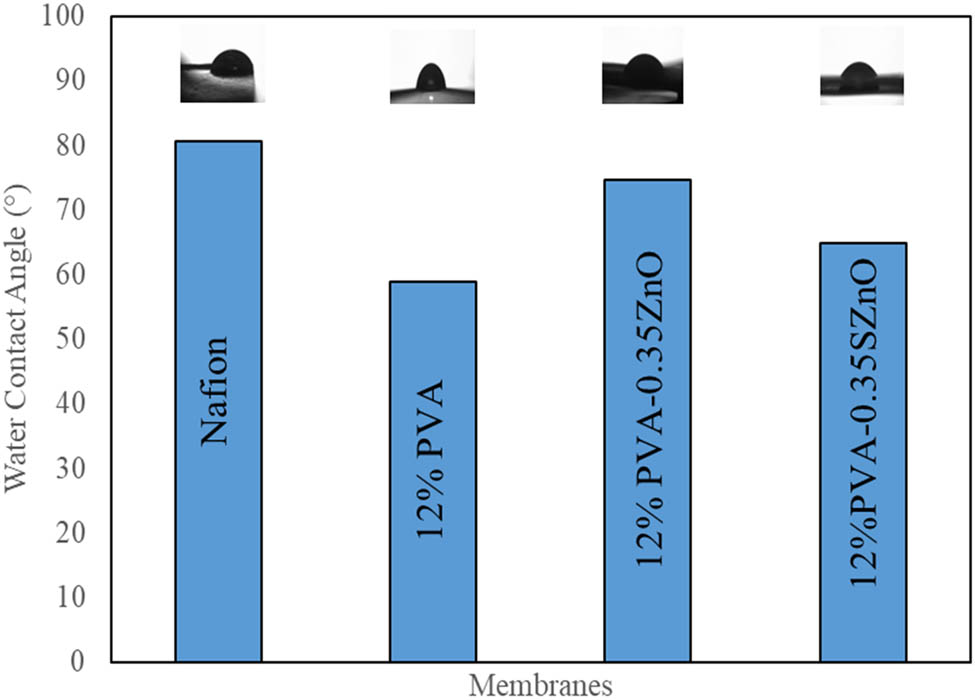
Contact angles of various membranes.
3.3 Performance of the prepared membranes in MFC
Nafion, 12% PVA, 12% PVA–0.35ZnO, and 12% PVA–0.35SZnO provided better results than other membranes and are hence selected for MFC performance. All the experiments lasted 8–10 days under the batch mode. A gradual growth in the voltage was seen when the time increased, after which a decrease in the voltage indicated the completion of the experiments. An external load of 1,800 Ω was given for all the MFC systems, making the circuit into closed systems. The experiment results of the prepared membranes were compared with the Nafion membranes. MFC operated with a Nafion membrane produced a maximum voltage of about 765 mV with a power density of about 219.679 mW·m−2. The performance of the membranes is shown in Figure 12. It was found that the maximum power density was obtained by the 12% PVA–0.35SZnO, which provides a maximum voltage of 654 mV with a power density of about 160.554 mW·m−2, which is lesser than the Nafion but provides better results than the other prepared membranes. The 12% PVA membrane has a maximum voltage and a power density of 492 mV and 90.8648 mW·m−2. Similarly, the maximum voltage and power density of 12% PVA–0.35ZnO is 582 mV and 127.1486 mW·m−2. Compared with PVA, PVA–ZnO, and PVA–SZnO, PVA–SZnO provide better results, which could be because of the negative ion group present and the better water uptake capacity of the membrane.
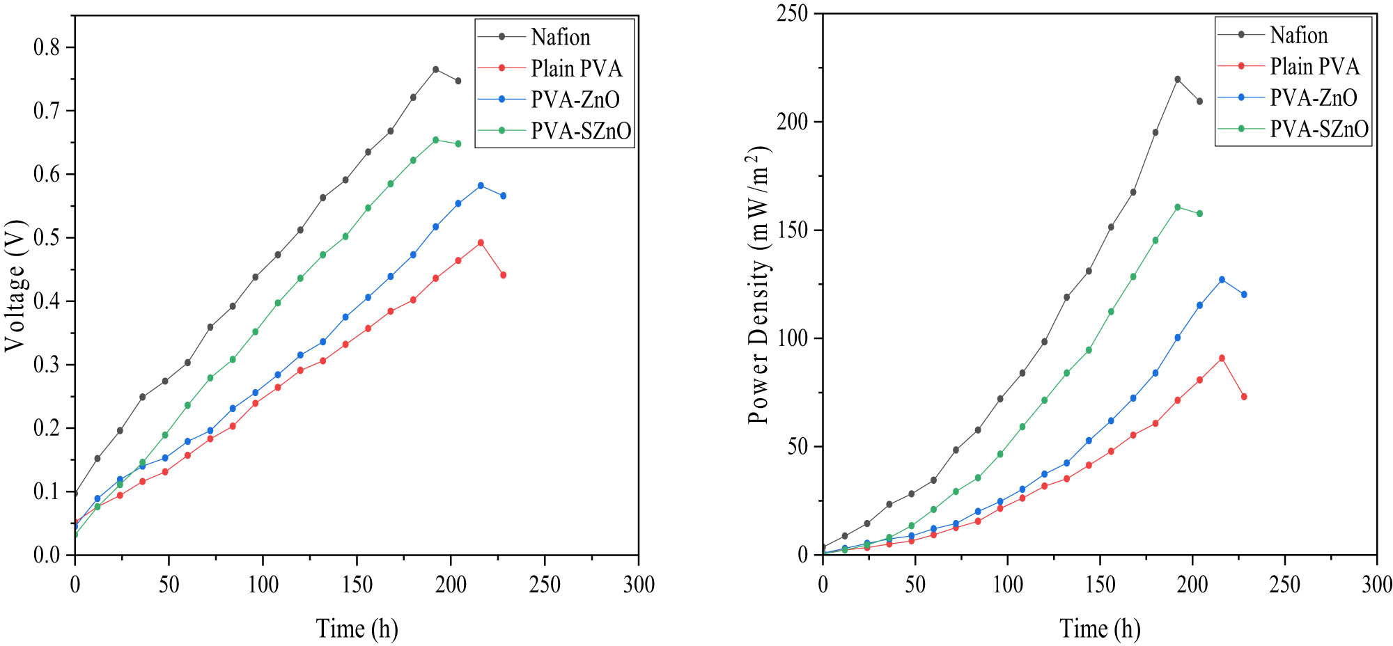
Performance of MFC based on voltage and power density.
The performance of the MFC was checked by measuring the COD removal, CE, and NER, which are tabulated in Table 3. The COD removal of all the membranes was in the range of 84%. Hence, it was found that the membrane does not have much influence on the COD removal efficiency. When the CE was checked, each membrane had different values, and Nafion had a maximum CE of 12.049%, followed by 12% PVA-0.35ZnO (10.7003%), 12% PVA-0.35ZnO (10.17525), and 12% PVA membrane (9.1582%). NER values provide an idea about the efficiency of the MFC based on the power generation independent of the reactor type and condition. The NER value for the Nafion is 0.1264 mWh·mL−1, PVA is 0.0581 mWh·mL−1, 12% PVA–0.35ZnO is 0.08129 mWh·mL−1, and 12% PVA–0.35SZnO is 0.095178 mWh·mL−1. Figure S9 shows the graphical representations of COD removal efficiency and NER.
Performance of the synthesized membranes in MFC
| Membrane | Voltage (mV) | Power density (mW·m−2) | Current density (mA·m−2) | COD removal (%) | CE (%) | NER (mWh·mL−1) |
|---|---|---|---|---|---|---|
| Nafion | 765 | 219.6791 | 287.1621 | 84.7855 | 12.049 | 0.1264 |
| 12% PVA | 492 | 90.8648 | 184.6846 | 84.3498 | 9.1582 | 0.0581 |
| 12% PVA–0.35ZnO | 582 | 127.1486 | 218.4685 | 84.517 | 10.70003 | 0.08129 |
| 12% PVA–0.35SZnO | 654 | 160.5541 | 245.4955 | 84.6179 | 10.1752 | 0.095178 |
The fouling of ions is a major concern for its long-time usage in the MFC. This factor was also considered in the preparation of the new membranes. ZnO exhibits antimicrobial properties that tend to reduce the microbes’ adherence to the membrane’s surface. Various studies show the antimicrobial effect of ZnO on a wide range of microbes [48]. Figure 13 shows the SEM image of the membrane taken before and after the experiment. Nafion membranes showed higher fouling, hence they had to be pre-treated before use. When visibly seen, the PVA, PVA–ZnO, and PVA–SZnO membranes show lower fouling rates. Even in the SEM image, it showed far lesser fouling than the Nafion membrane. The antimicrobial properties of PVA-ZnOs and PVA-SZnOs favor better proton conductivity than the PVA membrane. The fouling was not completely removed but was reduced; hence, this acts as a major advantage and can be used for a longer time than the commercially available Nafion membrane. Concerning this factor and the performance of the membrane in the MFC, which was close to those of Nafion, the prepared membrane can be a sustainable replacement for the Nafion membrane. This membrane can also be used for the treatment of bacterial-rich substrates like sewage wastewater as the membrane favors antimicrobial properties.
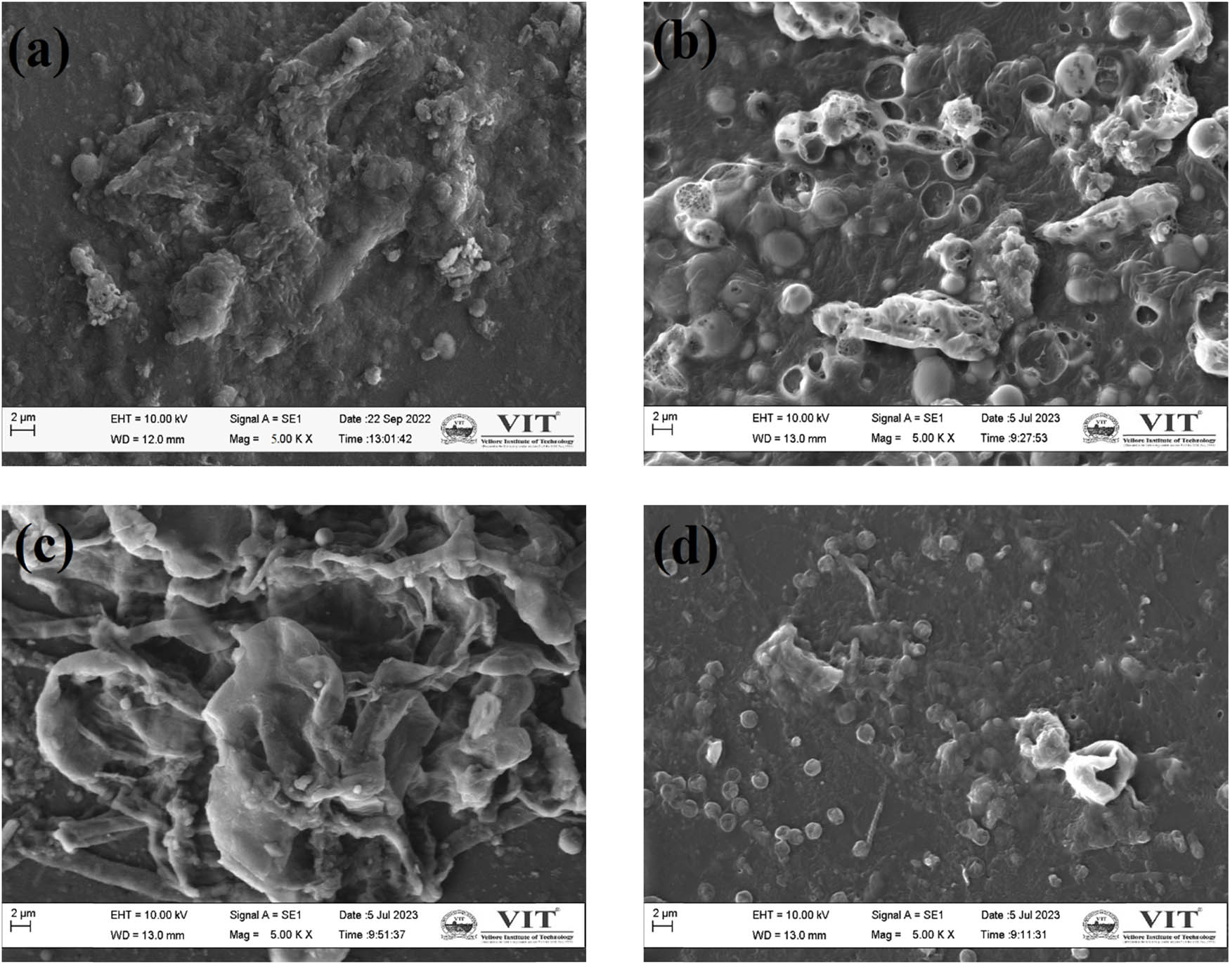
Surface morphology of the fouled membrane: (a) Nafion, (b) PVA, (c) PVA–0.35ZnO, and (d) PVA–0.35SZnO.
The results obtained from this work were compared with other studies, which are given in Table 4. It was found that the reactor with a lower volume provided better results than our results, but all the substrates used were synthetic wastewater [30,49]. Compared to the work done using the PVA-membrane electrode assembly, the prepared membranes in this work provide better results [50]. The PVA–glutaraldehyde membrane was operated at the same volume as in this study. The output obtained in this study was slightly greater than the crosslinked PVA membrane [19].
Comparison of the synthesized membranes with membranes from other studies
| Membrane | Reactor type | Substrate | Volume | Output | Ref. |
|---|---|---|---|---|---|
| PVA-membrane electrode assembly | Plate | Synthetic wastewater | 352 mL | 59–143 mW·m−2 | [50] |
| Crosslinked PVA (PVA–glutaraldehyde) | Dual | Domestic wastewater | 250 mL | 158.28 mW·m−2 | [19] |
| TiO2–Si–PVA | Dual | Synthetic wastewater | 25 mL | 247 mW·m−2 | [49] |
| SrTiO3–PVA | Dual | Synthetic wastewater | 25 mL | 216 mW·m−2 | [49] |
| Li–ZnO–PVA | Single | Acetate | 110 mL | 6.3 W·m−3 | [30] |
| SPEES–SZnO | Dual | Sewage wastewater | 300 mL | 142 mW·m−2 | [33] |
| PDA/TiO:ZnO | Single | Textile wastewater | 100 mL | 61 mW·m−2 | [51] |
| SPES-ZANPs | Dual | Sugar beet industrial wastewater | — | 142.75 mW·m−2 | [52] |
| PVA | Dual | Tannery wastewater | 250 mL | 90.8648 mW·m−2 | This study |
| PVA–ZnO | Dual | Tannery wastewater | 250 mL | 127.1486 mW·m−2 | This study |
| PVA–SZnO | Dual | Tannery wastewater | 250 mL | 160.554 mW·m−2 | This study |
| Nafion | Dual | Tannery wastewater | 250 mL | 219.679 mW·m−2 | This study |
3.4 Durability of the membrane
The prepared membrane has a reduced fouling rate compared to the Nafion membrane, as shown in Figure 13. To study the membrane’s long-term stability, the experiment was repeated for three cycles. After each cycle, the power density was found to be slightly lower. Before each cycle began, the membrane was treated using boiled distilled water until the visibly found fouling disappeared. After the third cycle, the membrane was treated, but the fouling remained visible. In the case of Nafion membrane, the membrane must be chemically pretreated before every use using sulfuric acid and hydrogen peroxide solution. However, after 4–5 uses, the Nafion membrane performance was significantly lower. The reduced fouling of the prepared membrane could be because of the reduced biofilm formation on the surface of the membrane with the presence of ZnO NPs, which produce −OH radicals that disrupt the bacterial cell wall that encounters the membrane. Another reason could be the lower internal resistance of the prepared membrane, which enhances the smooth proton transfer through the membrane, leading to lesser fouling [51].
3.5 Cost evaluation and environmental benefits of MFC
An economic analysis was conducted for the prepared membrane to evaluate the engineering feasibility. The primary factors include the cost of the chemicals used and the equipment costs (considering power consumption of 1 kW/h = Rs.7/-). Each chemical cost was taken from the Lobachemie Price list, and the equipment was obtained from a local vendor. Throughout the lab-scale operation of MFC, the labor cost was excluded. Considering the scaling-up process, the labor cost has to be included, which is an added expense. The approximate cost of the membrane was calculated and compared with the price of the commercially available Nafion membrane, as tabulated in Table 5. Compared to the price of the membranes, it is found that the prepared membrane is almost 34 times lower in cost than the Nafion membrane. Even though the prepared membrane is slightly inferior to the Nafion in terms of the performance of MFC, considering the cost, it can be termed advantageous. The detailed cost analysis of the overall MFC setup is listed in Table S1. The overall cost was calculated considering the cost of the reactor and electrodes. The overall cost for the operation of MFC with the prepared PVA–SZnO membrane resulted in a 39.488% reduction compared to the MFC operated with the Nafion.
Comparison of cost for the prepared PVA–SZnO membrane with Nafion
| Membrane | Cost in INR (0.1 m2 of membrane) | Cost in USD (0.1 m2 of membrane) | Cost (USD) of the original size (0.000314 m2) of PEM used in the MFC |
|---|---|---|---|
| PVA–SZnO | 92.8215 | 1.2418 | 0.0039 |
| Nafion | 3,150 | 42.1407 | 0.1324 |
MFC operation relies on the waste that is readily available and is discarded as waste. The conversion of waste to energy provides a huge environmental benefit. The PVA membrane used for the experiment could be easily discarded, as it is a biodegradable membrane. Since the NPs were prepared using green synthesis, it is free from toxic chemicals. Overall, this MFC could be used easily even in remote areas because of the readily available substrates and bacterial sources and are also environmentally friendly.
4 Conclusion
This study involves the biosynthesis of ZnO NPs using various plant sources and utilizing these NPs to develop cost-effective, durable, and better proton-conducting PEM for tannery wastewater treatment using MFC. ZnO NPs from Sphagneticola trilobata were found to provide better results and were further used for the membrane preparation. PEM was prepared with PVA as the backbone (PVA–ZnO and PVA–SZnO) by varying the weight of ZnO and SZnO. Sulfonation of ZnO NPs was done to enhance the proton-conducting nature of NPs, which was found to be effective based on the results obtained. Among all the prepared membranes, PVA–0.35 SZnO provided a better result and surpassed the Nafion membrane in the case of water uptake capacity (209%), oxygen mass transfer coefficient (1.09 × 10⁻⁶ cm·s−1), and oxygen diffusion coefficient (2.278 × 10⁻⁸ cm2·s−1). This prepared membrane provided results close to Nafion with a power density of 160.554 mW·m−2. Tannery wastewater treatment was also found to be effective with almost COD removal of about 84% obtained using this membrane. This membrane has a CE (10.1752%), which is slightly greater than that of Nafion (10.049%), and has a NER value of 0.095178 mWh·mL−1, which is slightly lower than that of Nafion (0.1264 mWh·mL−1). The results were comparable with Nafion 117 and other membranes obtained from the literature. The prepared membrane is a worthy innovation, as it has a considerable result in terms of cost for the PEM, which is 34 times lower than the cost of Nafion membrane making this an economically feasible option for implementing it on a larger scale. The membrane used is biodegradable, and the NPs used were also green-synthesized, and the overall membrane is free of all toxin chemicals. It may be concluded from the results obtained that the prepared PVA–SZnO membrane can be effectively used for the treatment of tannery wastewater and is potentially an ideal membrane for MFC operations for industrial-scale applications.
-
Funding information: The authors state no funding involved.
-
Author contributions: R.J.: conceptualization, methodology, formal analysis, investigation, and writing – original draft preparation. A.P.: writing – review, and editing. All authors have accepted responsibility for the entire content of this manuscript and approved its submission.
-
Conflict of interest: The authors state no conflict of interest.
-
Data availability statement: All data generated or analyzed during this study are included in this published article.
References
[1] Kesari, K. K., R. Soni, Q. M. S. Jamal, P. Tripathi, J. A. Lal, N. K. Jha, et al. Wastewater treatment and reuse: a review of its applications and health implications. Water, Air, and Soil Pollution, Vol. 232, No. 5, 2021, id. 208.10.1007/s11270-021-05154-8Search in Google Scholar
[2] Jones, E. R., M. T. H. Van Vliet, M. Qadir, and M. F. P. Bierkens. Country-level and gridded estimates of wastewater production, collection, treatment and reuse. Earth System Science Data, Vol. 13, No. 2, 2021, pp. 237–254.10.5194/essd-13-237-2021Search in Google Scholar
[3] Ramaswamy, P., N. E. Wong, and G. K. H. Shimizu. MOFs as proton conductors-challenges and opportunities. Chemical Society Reviews, Vol. 43, No. 16, 2014, pp. 5913–5932.10.1039/C4CS00093ESearch in Google Scholar
[4] Lu, M., S. Chen, S. Babanova, S. Phadke, M. Salvacion, A. Mirhosseini, et al. Long-term performance of a 20-L continuous flow microbial fuel cell for treatment of brewery wastewater. Journal of Power Sources, Vol. 356, 2017, pp. 274–287.10.1016/j.jpowsour.2017.03.132Search in Google Scholar
[5] Li, X., Y. Li, X. Zhang, X. Zhao, Y. Sun, L. Weng, et al. Long-term effect of biochar amendment on the biodegradation of petroleum hydrocarbons in soil microbial fuel cells. Science of the Total Environment, Vol. 651, 2019, pp. 796–806.10.1016/j.scitotenv.2018.09.098Search in Google Scholar PubMed
[6] Wu, Y., X. Zhao, M. Jin, Y. Li, S. Li, F. Kong, et al. Copper removal and microbial community analysis in single-chamber microbial fuel cell. Bioresource Technology, Vol. 253, No. 2017, 2018, pp. 372–377.10.1016/j.biortech.2018.01.046Search in Google Scholar PubMed
[7] Sivasankar, P., S. Poongodi, P. Seedevi, M. Sivakumar, T. Murugan, and S. Loganathan. Bioremediation of wastewater through a quorum sensing triggered MFC: A sustainable measure for waste to energy concept. Journal of Environmental Management, Vol. 237, No. 2018, 2019, pp. 84–93.10.1016/j.jenvman.2019.01.075Search in Google Scholar PubMed
[8] Caizán-Juanarena, L., C. Borsje, T. Sleutels, D. Yntema, C. Santoro, I. Ieropoulos, et al. Combination of bioelectrochemical systems and electrochemical capacitors: Principles, analysis and opportunities. Biotechnology Advances, Vol. 39, No. 2019, 2020, id. 107456.10.1016/j.biotechadv.2019.107456Search in Google Scholar PubMed PubMed Central
[9] Clauwaert, P., P. Aelterman, T. H. Pham, L. De Schamphelaire, M. Carballa, K. Rabaey, et al. Minimizing losses in bio-electrochemical systems: The road to applications. Applied Microbiology and Biotechnology, Vol. 79, No. 6, 2008, pp. 901–913.10.1007/s00253-008-1522-2Search in Google Scholar PubMed
[10] Daud, S. M., W. R. Wan Daud, M. H. Abu Bakar, B. H. Kim, M. R. Somalu, J. M. Jahim, et al. A comparison of long-term fouling performance by zirconia ceramic filter and cation exchange in microbial fuel cells. International Biodeterioration & Biodegradation, Vol. 136, 2019, pp. 63–70.10.1016/j.ibiod.2018.11.001Search in Google Scholar
[11] Do, M. H., H. H. Ngo, W. S. Guo, Y. Liu, S. W. Chang, D. D. Nguyen, et al. Challenges in the application of microbial fuel cells to wastewater treatment and energy production: A mini review. Science of the Total Environment, Vol. 639, 2018, pp. 910–920.10.1016/j.scitotenv.2018.05.136Search in Google Scholar PubMed
[12] Jia, H., Y. Wang, T. Wang, Y. Dong, W. L. Li, J. P. Li, et al. Advances in microbial fuel cells for wastewater treatment. Renewable and Sustainable Energy Reviews, Vol. 71, No. 2016, 2017, pp. 388–403.10.1016/j.rser.2016.12.069Search in Google Scholar
[13] Raja Rafidah, R. S., W. Rashmi, M. Khalid, W. Y. Wong, and J. Priyanka. Recent progress in the development of aromatic polymer-based proton exchange membranes for fuel cell applications. Polymers (Basel), Vol. 12, No. 5, 2020, id. 1061.10.3390/polym12051061Search in Google Scholar PubMed PubMed Central
[14] Tiwari, B. R., M. T. Noori, and M. M. Ghangrekar. A novel low cost polyvinyl alcohol-Nafion-borosilicate membrane separator for microbial fuel cell. Materials Chemistry and Physics, Vol. 182, 2016, pp. 86–93.10.1016/j.matchemphys.2016.07.008Search in Google Scholar
[15] Fan, Y., H. Hu, and H. Liu. Enhanced Coulombic efficiency and power density of air-cathode microbial fuel cells with an improved cell configuration. Journal of Power Sources, Vol. 171, No. 2, 2007, pp. 348–354.10.1016/j.jpowsour.2007.06.220Search in Google Scholar
[16] Ayyaru, S., P. Letchoumanane, S. Dharmalingam, and A. R. Stanislaus. Performance of sulfonated polystyrene-ethylene-butylene-polystyrene membrane in microbial fuel cell for bioelectricity production. Journal of Power Sources, Vol. 217, 2012, pp. 204–208.10.1016/j.jpowsour.2012.05.053Search in Google Scholar
[17] Xu, J., G. P. Sheng, H. W. Luo, W. W. Li, L. F. Wang, and H. Q. Yu. Fouling of proton exchange membrane (PEM) deteriorates the performance of microbial fuel cell. Water Research, Vol. 46, No. 6, 2012, pp. 1817–1824.10.1016/j.watres.2011.12.060Search in Google Scholar PubMed
[18] Leong, J. X., W. R. W. Daud, M. Ghasemi, A. Ahmad, M. Ismail, and K. Ben Liew. Composite membrane containing graphene oxide in sulfonated polyether ether ketone in microbial fuel cell applications. International Journal of Hydrogen Energy, Vol. 40, No. 35, 2015, pp. 11604–11614.10.1016/j.ijhydene.2015.04.082Search in Google Scholar
[19] Das, B., S. S. Gaur, A. R. Katha, C. T. Wang, and V. Katiyar. Crosslinked poly(vinyl alcohol) membrane as separator for domestic wastewater fed dual chambered microbial fuel cells. International Journal of Hydrogen Energy, Vol. 46, No. 10, 2021, pp. 7073–7086.10.1016/j.ijhydene.2020.11.213Search in Google Scholar
[20] Chen, G., B. Wei, Y. Luo, B. E. Logan, and M. A. Hickner. Polymer separators for high-power, high-efficiency microbial fuel cells. ACS Applied Materials & Interfaces, Vol. 4, No. 12, 2012, pp. 6454–6457.10.1021/am302301tSearch in Google Scholar PubMed
[21] Hasani-Sadrabadi, M. M., E. Dashtimoghadam, F. S. Majedi, K. Kabiri, M. Solati-Hashjin, and H. Moaddel. Novel nanocomposite proton exchange membranes based on Nafion® and AMPS-modified montmorillonite for fuel cell applications. Journal of Membrane Science, Vol. 365, No. 1–2, 2010, pp. 286–293.10.1016/j.memsci.2010.09.014Search in Google Scholar
[22] Borja-Maldonado, F. and M.Á. López Zavala. Contribution of configurations, electrode and membrane materials, electron transfer mechanisms, and cost of components on the current and future development of microbial fuel cells. Heliyon, Vol. 8, No. 7, 2022, id. e09849.10.1016/j.heliyon.2022.e09849Search in Google Scholar PubMed PubMed Central
[23] Das, I., S. Das, S. Sharma, and M. M. Ghangrekar. Ameliorated performance of a microbial fuel cell operated with an alkali pre-treated clayware ceramic membrane. International Journal of Hydrogen Energy, Vol. 45, No. 33, 2020, pp. 16787–16798.10.1016/j.ijhydene.2020.04.157Search in Google Scholar
[24] Fan, L. P. and T. Gao. Applications of nanoscale polypyrrole proton exchange membrane in microbial fuel cells. International Journal of Electrochemical Science, Vol. 14, No. 1, 2019, pp. 470–480.10.20964/2019.01.41Search in Google Scholar
[25] Chakraborty, I., S. Das, B. K. Dubey, and M. M. Ghangrekar. Novel low cost proton exchange membrane made from sulphonated biochar for application in microbial fuel cells. Materials Chemistry and Physics, Vol. 239, No. 2019, 2020, id. 122025.10.1016/j.matchemphys.2019.122025Search in Google Scholar
[26] Daries Bella, R. S., G. Hirankumar, R. Navanietha Krishnaraj, and D. Prem Anand. Novel proton conducting polymer electrolyte and its application in microbial fuel cell. Materials Letters, Vol. 164, 2016, pp. 551–553.10.1016/j.matlet.2015.11.066Search in Google Scholar
[27] Choi, K. J. and H. W. Jang. One-dimensional oxide nanostructures as gas-sensing materials: Review and issues. Sensors, Vol. 10, No. 4, 2010, pp. 4083–4099.10.3390/s100404083Search in Google Scholar PubMed PubMed Central
[28] Asadpour, S., M. Kooravand, and A. Asfaram. A review on zinc oxide/poly(vinyl alcohol) nanocomposites: Synthesis, characterization and applications. Journal of Cleaner Production, Vol. 362, 2022, id. 132297.10.1016/j.jclepro.2022.132297Search in Google Scholar
[29] Sirelkhatim, A., S. Mahmud, A. Seeni, N. Kaus, L. C. Ann, S. Bakhori, et al. Review on zinc oxide nanoparticles: Antibacterial activity and toxicity mechanism. Nanomicro Letters, Vol. 7, No. 3, 2015, pp. 219–242.10.1007/s40820-015-0040-xSearch in Google Scholar PubMed PubMed Central
[30] Chauhan, S., A. Kumar, S. Pandit, A. Vempaty, M. Kumar, B. S. Thapa, et al. Investigating the performance of a zinc oxide impregnated polyvinyl alcohol-based low-cost cation exchange membrane in microbial fuel cells. Membranes (Basel), Vol. 13, No. 1, 2023, id. 55.10.3390/membranes13010055Search in Google Scholar PubMed PubMed Central
[31] Palanisamy, G., S. Thangarasu, and T. H. Oh. Effect of sulfonated inorganic additives incorporated hybrid composite polymer membranes on enhancing the performance of microbial fuel cells. Polymers (Basel), Vol. 15, No. 5, 2023, id. 1294.10.3390/polym15051294Search in Google Scholar PubMed PubMed Central
[32] Yedurkar, S., C. Maurya, and P. Mahanwar. Biosynthesis of zinc oxide nanoparticles using ixora coccinea leaf extract – a green approach. Open Journal of Synthesis Theory and Applications, Vol. 5, No. 1, 2016, pp. 1–14.10.4236/ojsta.2016.51001Search in Google Scholar
[33] Kugarajah, V., M. Sugumar, E. Swaminathan, N. Balasubramani, and S. Dharmalingam. Investigation on sulphonated zinc oxide nanorod incorporated sulphonated poly (1,4-phenylene ether ether sulfone) nanocomposite membranes for improved performance of microbial fuel cell. International Journal of Hydrogen Energy, Vol. 46, No. 42, 2021, pp. 22134–22148.10.1016/j.ijhydene.2021.04.067Search in Google Scholar
[34] González-Pabón, M. J., F. Figueredo, D. C. Martínez-Casillas, and E. Cortón. Characterization of a new composite membrane for point of need paper-based micro-scale microbial fuel cell analytical devices. PLoS One, Vol. 14, No. 9, 2019, pp. 1–22.10.1371/journal.pone.0222538Search in Google Scholar PubMed PubMed Central
[35] Khan, M. Q., D. Kharaghani, N. Nishat, A. Shahzad, T. Hussain, Z. Khatri, et al. Preparation and characterizations of multifunctional PVA/ZnO nanofibers composite membranes for surgical gown application. Journal of Materials Research and Technology, Vol. 8, No. 1, 2019, pp. 1328–1334.10.1016/j.jmrt.2018.08.013Search in Google Scholar
[36] Kumar, P. and R. P. Bharti. Nanocomposite polymer electrolyte membrane for high performance microbial fuel cell: Synthesis, characterization and application. Journal of the Electrochemical Society, Vol. 166, No. 15, 2019, pp. F1190–F1199.10.1149/2.0671915jesSearch in Google Scholar
[37] Shabani, M., H. Younesi, M. Pontié, A. Rahimpour, M. Rahimnejad, and A. A. Zinatizadeh. A critical review on recent proton exchange membranes applied in microbial fuel cells for renewable energy recovery. Journal of Cleaner Production, Vol. 264, 2020, id. 121446.10.1016/j.jclepro.2020.121446Search in Google Scholar
[38] Chouke, P. B., T. Shrirame, A. K. Potbhare, A. Mondal, A. R. Chaudhary, S. Mondal, et al. Bioinspired metal/metal oxide nanoparticles: A road map to potential applications. Materials Today Advances, Vol. 16, 2022, id. 100314.10.1016/j.mtadv.2022.100314Search in Google Scholar
[39] Prabhu, Y. T., K. V. Rao, V. S. S. Kumar, and B. S. Kumari. X-ray analysis by Williamson-Hall and size-strain plot methods of ZnO nanoparticles with fuel variation. World Journal of Nano Science and Engineering, Vol. 4, No. 1, 2014, pp. 21–28.10.4236/wjnse.2014.41004Search in Google Scholar
[40] Nikam, C. U., S. R. Kadam, R. S. Shitole, A. P. Birajdar, V. K. Barote, S. R. Wadgnae, et al. Williamson-Hall and Size-strain plot based micro-structural analysis and evaluation of elastic properties of Dy3 + substituted Co-Zn nano-spinels. Journal of Physics: Conference Series, Vol. 2426, No. 1, 2023, id. 012029.10.1088/1742-6596/2426/1/012029Search in Google Scholar
[41] Mathin, S. K. A., M. D. Raju, and D. R. S. Reddy. Green synthesis, characterization and application study of zinc nano particles synthesized using aqueous root extract of sphagneticola trilobata lin. Research Journal of Pharmacy and Technology, Vol. 13, No. 12, 2020, pp. 5972–5978.10.5958/0974-360X.2020.01042.2Search in Google Scholar
[42] Yassin, M. T., A. A. F. Mostafa, A. A. Al-Askar, and F. O. Al-Otibi. Facile green synthesis of zinc oxide nanoparticles with potential synergistic activity with common antifungal agents against multidrug-resistant candidal strains. Crystals (Basel), Vol. 12, No. 6, 2022, pp. 1–20.10.3390/cryst12060774Search in Google Scholar
[43] Sau, S., S. Pandit, and S. Kundu. Crosslinked poly (vinyl alcohol): Structural, optical and mechanical properties. Surfaces and Interfaces, Vol. 25, No. 2020, 2021, id. 101198.10.1016/j.surfin.2021.101198Search in Google Scholar
[44] Otaibi, A. A., M. B. Patil, S. B. Rajamani, S. N. Mathad, A. Y. Patil, M. K. Amshumali, et al. Development and testing of zinc oxide embedded sulfonated poly (vinyl alcohol) nanocomposite membranes for fuel cells. Crystals (Basel), Vol. 12, No. 12, 2022, id. 1739.10.3390/cryst12121739Search in Google Scholar
[45] Moghadasin, M. H., T. Mohammadi, and M. Ahmadzadeh Tofighy. Synthesis and characterization of PVA mixed matrix membrane containing NaP zeolite/charcoal-based graphene oxide nanohybrid for dehydration of isopropanol by pervaporation. Industrial & Engineering Chemistry Research, Vol. 62, No. 47, 2023, pp. 20360–20380.10.1021/acs.iecr.3c02999Search in Google Scholar
[46] Liu, S. H. and K. Y. Lee. Optimization preparation of composite membranes as proton exchange membrane for gaseous acetone fed microbial fuel cells. Journal of Power Sources, Vol. 509, 2021, id. 230368.10.1016/j.jpowsour.2021.230368Search in Google Scholar
[47] Prabhu, N. V. and D. Sangeetha. Characterization and performance study of sulfonated poly ether ether ketone/Fe3O4 nano composite membrane as electrolyte for microbial fuel cell. Chemical Engineering Journal, Vol. 243, 2014, pp. 564–571.10.1016/j.cej.2013.12.103Search in Google Scholar
[48] Tiwari, V., N. Mishra, K. Gadani, P. S. Solanki, N. A. Shah, and M. Tiwari. Mechanism of anti-bacterial activity of zinc oxide nanoparticle against Carbapenem-Resistant Acinetobacter baumannii. Frontiers in Microbiology, Vol. 9, 2018, pp. 1–10.10.3389/fmicb.2018.01218Search in Google Scholar PubMed PubMed Central
[49] Bhowmick, G. D., D. Dhar, M. M. Ghangrekar, and R. Banerjee. TiO2-Si- or SrTiO3-Si-impregnated PVA–based low-cost proton exchange membranes for application in microbial fuel cell. Ionics (Kiel), Vol. 26, No. 12, 2020, pp. 6195–6205.10.1007/s11581-020-03779-zSearch in Google Scholar
[50] Liu, S. H., C. H. Wu, and C. W. Lin. Enhancement of bioelectricity generation for an air-cathode microbial fuel cell using polyvinyl alcohol-membrane electrode assemblies. Biochemical Engineering Journal, Vol. 128, 2017, pp. 210–217.10.1016/j.bej.2017.10.003Search in Google Scholar
[51] Bahamonde Soria, R., B. D. Chinchin, D. Arboleda, Y. Zhao, P. Bonilla, B.Van der Bruggen, et al. Effect of the bio-inspired modification of low-cost membranes with TiO2:ZnO as microbial fuel cell membranes. Chemosphere, Vol. 291, 2022, id. 132840.10.1016/j.chemosphere.2021.132840Search in Google Scholar PubMed
[52] Shirvani, B., M. Rahimi, and S. Zinadini. Exploring the potential of anti-bacterial and conductive ZnO–Al2O3/SPES proton exchange membrane applied in MFC for sustainable energy generation and sugar beet industry effluent treatment. Renewable Energy, Vol. 231, No. 2023, 2024, id. 121003.10.1016/j.renene.2024.121003Search in Google Scholar
© 2025 the author(s), published by De Gruyter
This work is licensed under the Creative Commons Attribution 4.0 International License.
Articles in the same Issue
- Review Articles
- Utilization of steel slag in concrete: A review on durability and microstructure analysis
- Technical development of modified emulsion asphalt: A review on the preparation, performance, and applications
- Recent developments in ultrasonic welding of similar and dissimilar joints of carbon fiber reinforcement thermoplastics with and without interlayer: A state-of-the-art review
- Unveiling the crucial factors and coating mitigation of solid particle erosion in steam turbine blade failures: A review
- From magnesium oxide, magnesium oxide concrete to magnesium oxide concrete dams
- Properties and potential applications of polymer composites containing secondary fillers
- A scientometric review on the utilization of copper slag as a substitute constituent of ordinary Portland cement concrete
- Advancement of additive manufacturing technology in the development of personalized in vivo and in vitro prosthetic implants
- Recent advance of MOFs in Fenton-like reaction
- A review of defect formation, detection, and effect on mechanical properties of three-dimensional braided composites
- Non-conventional approaches to producing biochars for environmental and energy applications
- Review of the development and application of aluminum alloys in the nuclear industry
- Advances in the development and characterization of combustible cartridge cases and propellants: Preparation, performance, and future prospects
- Recent trends in rubberized and non-rubberized ultra-high performance geopolymer concrete for sustainable construction: A review
- Cement-based materials for radiative cooling: Potential, material and structural design, and future prospects
- A comprehensive review: The impact of recycling polypropylene fiber on lightweight concrete performance
- A comprehensive review of preheating temperature effects on reclaimed asphalt pavement in the hot center plant recycling
- Exploring the potential applications of semi-flexible pavement: A comprehensive review
- A critical review of alkali-activated metakaolin/blast furnace slag-based cementitious materials: Reaction evolution and mechanism
- Dispersibility of graphene-family materials and their impact on the properties of cement-based materials: Application challenges and prospects
- Research Articles
- Investigation of the corrosion performance of HVOF-sprayed WC-CoCr coatings applied on offshore hydraulic equipment
- A systematic review of metakaolin-based alkali-activated and geopolymer concrete: A step toward green concrete
- Evaluation of color matching of three single-shade composites employing simulated 3D printed cavities with different thicknesses using CIELAB and CIEDE2000 color difference formulae
- Novel approaches in prediction of tensile strain capacity of engineered cementitious composites using interpretable approaches
- Effect of TiB2 particles on the compressive, hardness, and water absorption responses of Kulkual fiber-reinforced epoxy composites
- Analyzing the compressive strength, eco-strength, and cost–strength ratio of agro-waste-derived concrete using advanced machine learning methods
- Tensile behavior evaluation of two-stage concrete using an innovative model optimization approach
- Tailoring the mechanical and degradation properties of 3DP PLA/PCL scaffolds for biomedical applications
- Optimizing compressive strength prediction in glass powder-modified concrete: A comprehensive study on silicon dioxide and calcium oxide influence across varied sample dimensions and strength ranges
- Experimental study on solid particle erosion of protective aircraft coatings at different impact angles
- Compatibility between polyurea resin modifier and asphalt binder based on segregation and rheological parameters
- Fe-containing nominal wollastonite (CaSiO3)–Na2O glass-ceramic: Characterization and biocompatibility
- Relevance of pore network connectivity in tannin-derived carbons for rapid detection of BTEX traces in indoor air
- A life cycle and environmental impact analysis of sustainable concrete incorporating date palm ash and eggshell powder as supplementary cementitious materials
- Eco-friendly utilisation of agricultural waste: Assessing mixture performance and physical properties of asphalt modified with peanut husk ash using response surface methodology
- Benefits and limitations of N2 addition with Ar as shielding gas on microstructure change and their effect on hardness and corrosion resistance of duplex stainless steel weldments
- Effect of selective laser sintering processing parameters on the mechanical properties of peanut shell powder/polyether sulfone composite
- Impact and mechanism of improving the UV aging resistance performance of modified asphalt binder
- AI-based prediction for the strength, cost, and sustainability of eggshell and date palm ash-blended concrete
- Investigating the sulfonated ZnO–PVA membrane for improved MFC performance
- Strontium coupling with sulphur in mouse bone apatites
- Transforming waste into value: Advancing sustainable construction materials with treated plastic waste and foundry sand in lightweight foamed concrete for a greener future
- Evaluating the use of recycled sawdust in porous foam mortar for improved performance
- Improvement and predictive modeling of the mechanical performance of waste fire clay blended concrete
- Polyvinyl alcohol/alginate/gelatin hydrogel-based CaSiO3 designed for accelerating wound healing
- Research on assembly stress and deformation of thin-walled composite material power cabin fairings
- Effect of volcanic pumice powder on the properties of fiber-reinforced cement mortars in aggressive environments
- Analyzing the compressive performance of lightweight foamcrete and parameter interdependencies using machine intelligence strategies
- Selected materials techniques for evaluation of attributes of sourdough bread with Kombucha SCOBY
- Establishing strength prediction models for low-carbon rubberized cementitious mortar using advanced AI tools
- Investigating the strength performance of 3D printed fiber-reinforced concrete using applicable predictive models
- An eco-friendly synthesis of ZnO nanoparticles with jamun seed extract and their multi-applications
- The application of convolutional neural networks, LF-NMR, and texture for microparticle analysis in assessing the quality of fruit powders: Case study – blackcurrant powders
- Study of feasibility of using copper mining tailings in mortar production
- Shear and flexural performance of reinforced concrete beams with recycled concrete aggregates
- Advancing GGBS geopolymer concrete with nano-alumina: A study on strength and durability in aggressive environments
- Leveraging waste-based additives and machine learning for sustainable mortar development in construction
- Study on the modification effects and mechanisms of organic–inorganic composite anti-aging agents on asphalt across multiple scales
- Morphological and microstructural analysis of sustainable concrete with crumb rubber and SCMs
- Structural, physical, and luminescence properties of sodium–aluminum–zinc borophosphate glass embedded with Nd3+ ions for optical applications
- Eco-friendly waste plastic-based mortar incorporating industrial waste powders: Interpretable models for flexural strength
- Bioactive potential of marine Aspergillus niger AMG31: Metabolite profiling and green synthesis of copper/zinc oxide nanocomposites – An insight into biomedical applications
- Preparation of geopolymer cementitious materials by combining industrial waste and municipal dewatering sludge: Stabilization, microscopic analysis and water seepage
- Seismic behavior and shear capacity calculation of a new type of self-centering steel-concrete composite joint
- Sustainable utilization of aluminum waste in geopolymer concrete: Influence of alkaline activation on microstructure and mechanical properties
- Optimization of oil palm boiler ash waste and zinc oxide as antibacterial fabric coating
- Special Issue on Recent Advancement in Low-carbon Cement-based Materials - Part II
- Investigating the effect of locally available volcanic ash on mechanical and microstructure properties of concrete
- Flexural performance evaluation using computational tools for plastic-derived mortar modified with blends of industrial waste powders
- Foamed geopolymers as low carbon materials for fire-resistant and lightweight applications in construction: A review
- Autogenous shrinkage of cementitious composites incorporating red mud
- Special Issue on AI-Driven Advances for Nano-Enhanced Sustainable Construction Materials
- Advanced explainable models for strength evaluation of self-compacting concrete modified with supplementary glass and marble powders
- Special Issue on Advanced Materials for Energy Storage and Conversion
- Innovative optimization of seashell ash-based lightweight foamed concrete: Enhancing physicomechanical properties through ANN-GA hybrid approach