Rheological behavior of fire-fighting foams during their application – a new experimental set-up and protocol for foam performance qualification
-
Aubin Puget


Abstract
The flow behavior of fire-fighting foams is an important factor in its performance as it largely determines how well and how fast the foam covers the burning fluid and seals it from oxygen. The flow characteristics, as well as the performance of such a foam is evaluated by a newly designed rheological cell and rheological experimental protocols mimicking a fire-fighting practice. Experiments are performed under conditions that apply while applying the foam (high shear of 10 s−1, continuous fresh foam feed, which limits draining and coarsening) and conditions that apply once the foam is deposited (low shear of 0.5 s−1, no foam feed allowing for draining and coarsening). This yields valuable insights. Very strong differences in flow behavior are observed changing from very well-flowing behavior on application to very viscous/stiff after deposition. Also, the shear-thinning character of foam flow was studied. After changing from a steady foam feed to a foam at rest situation, a transition period of complex flow behavior could be observed. This indicates that relaxation and restructuring processes of the foam bubbles that were deformed underflow are taking place. After this transition period, the effects of draining and coarsening become visible.
1 Introduction
Aqueous foams are suspensions of bubbles inside a continuous aqueous phase. The bubbles are surrounded by a liquid film, which serves to define the bubbles. This film is stabilized by amphiphilic molecules, compromising a hydrophilic part (head group) interacting with the water phase and one or more hydrophobic tail groups – surfactants that point to the air inside of the bubbles. Characteristic parameters defining foams are structural and geometric features like the gas and liquid fraction. These properties determine the rigidity of the foam, the average bubble size, and the bubble size distribution or polydispersity. When the gas fraction approaches unity, the foam is called dry and is very rigid. On the other side, by lowering the gas fraction, the foam becomes more wet, and the gas bubbles will become more spherical until a critical gas fraction is reached, and the bubbles lose contact – a bubbly liquid is formed [1,2,3,4,5,6].
The properties of foams are intimately related to their structure. Because of their multiscale nature, liquid foams display a complex mechanical behavior: they have elastic, plastic, and viscous properties. When a foam yields, plastic flow starts as a consequence of local bubble rearrangements to relax the subjected stresses. The bubble rearrangements are irreversible, and the foam flows like a non-Newtonian fluid [7]. Depending on the applied strain rates either bubbles rearrange intermittently or deformation under shear occurs, resulting finally in lamellar flow. Upon reduction of stress, the foam reverts to an elastic liquid when the stress falls below the yield stress. On the other side, slow flow is coupled to aging via coarsening-induced bubble rearrangements and finally stiffening due to extensive drainage.
This qualifies foams as complex fluids, like colloidal and granular suspensions, polymers, pastes, slurries, and emulsions [8], and the measurement and understanding of their complex mechanical response belong to the field of foam rheology. Foam rheology is a consequently complex challenge as it is difficult to measure its viscosity in a way that resembles reality. Therefore, dedicated methods need to be developed to better understand foam spreading and drainage. The properties of the foam result from the interplay between processes over different length scales and timescales.
Although many foam rheology measurements have been made, the reports often vary from paper to paper due to different approaches, experimental set-ups, and foam characteristics. A classical way to measure rheology is to apply shear with different rates in various geometries: between two planes, a cone and a plane, or two cylinders (the so-called Couette rheometer) [9,10,11,12]. Another classical experiment in rheometry subjects the foam to an oscillatory shear of angular frequency with varying strain amplitudes. These rheometric studies confirm in general that below a yield strain or a yield stress, foams behave as viscoelastic solids, while they flow as non-Newtonian liquids above yield. Alternatively pipe rheometers are also used for the measurement of flow behavior of aqueous foams [13,14]. Another configuration to measure rheological properties of especially non-Newtonian fluids, which can display large slip effects at smooth walls is the vane geometry [15]. The application of the vane geometry for the study of fire-fighting foams was described already in 1976 [16] based on the foam viscosimeter described by French [17]. This geometry offers a way of introducing the testing element – a thin-bladed vane – into a structured liquid with minimal sample disturbance, making it very suitable for materials such as foam. Only a few direct observations of the local velocity field in foams or concentrated emulsions flowing under homogeneous applied shear stress have been published: an MRI study of an emulsion, steadily sheared in a cone and plate geometry, has shown coexisting liquid-like and solid-like regions [18]. These data indicate that the width of the solid-like region decreases with increasing cone rotation velocity and thus with effective strain rate, so homogeneous flow may occur for sufficiently high strain rates.
For any rheological measurements, numerous parameters must be considered and controlled to gain reproducible results:
The foam quality, i.e., gas volume fraction,
The foam texture (bubbles’ size distribution),
The size of the measurement apparatus compared to the bubbles size,
The influence of foam production method,
Wall slip phenomena and foam compressibility.
Foam must be stable and must not evolve during the measurement time. This is especially challenging since foams are unstable systems: a foam evolves by drainage of the liquid phase with time, by gas bubbles coalescence, or by Ostwald ripening. Under a weak shear stress, foam can flow in “plug flow” by slipping on a thin fluid layer at the wall [7], and therefore, conditions need to be chosen to minimize wall slip.
The most common foam creation method consists of injecting surfactant solution and gas through a porous medium [2]. By varying the gas and fluid flow rate ratio, it is possible to change foam quality. This porous medium is often constituted of sand [19,20,21] or packed beds of glass beads [22]. By varying gas and fluid injection rates into porous media, foam texture may be modified.
In this article, we first provide an introduction to the special case of fire-fighting foams, which is followed by a description of the procedures applied during the execution of the experiments. We then discuss the fundamental results obtained and derive conclusions from the experimental results.
2 Fire-fighting foams
Foams are widely used for fighting fires of liquid fuels. The way a fire is extinguished using a foam is by covering the fire with an aqueous film that serves as a blanket and the foam over it serves as an isolation and a water reservoir to expand/reform the covering film. That way, not only the fire is cooled down by the water contained in the foam, but the fire is also covered by a foam blanket that deprives the fire of combustion. Important is that the foam spread quickly on the fuel surface and stays after complete coverage intact to separate the fuel and fuel fume from the flame until the fire is extinguished.
The specific objectives of the present work are to systematically study the stability of foams using in situ rheology as well as dynamic structural changes on the bubble scale. Most commonly, foam stability is investigated by monitoring the changes in the height of bulk foam in vertical columns over time.
For the characterization and understanding of the functional behavior of such fire-fighting foams, a newly designed shear cell that enables constant drainage was developed excluding also the existence and interference of several different phases in the cell. Special attention has been paid to the continuous foam generation and feed into the cell to enable a measurement of the rheology in conditions like the ones during the application of a foam to a liquid surface.
Experiments were executed, and the results are discussed, especially for two moments of the applications of foams used for fire-fighting,
The application of a foam (spraying).
The behavior of a foam at rest when the blanket has been formed and acts to separate the flames and air from the fuel.
Inferences regarding foam coarsening and coalescence can be detected as well as drainage and coupled with morphological changes detected on the bubble scale. The goal of the investigation was to link the rheology of the foam to the performance of the foam in applications such as fire-fighting foam and to assess and predict foam properties like spreading or sealing to finally judge performance and function as a tool for the development of better working formulations.
3 Experimental
Foam rheology measurements have been done on two different formulations, one showing Newtonian behavior (Newtonian formulation, NF), whereas the other one shows shear-thinning behavior (non-Newtonian formulation, NNF). These formulations are used in commercial fire-fighting systems, whereby the shear-thinning formulation generates a more stable foam with longer drainage times. Consequently, the viscosities of foam-generating liquids differ in their viscosity characteristics, especially in the low shear rate range (Figure 1).

Viscosity profiles of NF and NNF-generating formulations as a function of shear rate. The NF (blue line) maintains a constant viscosity, while the NNF (red line) exhibits shear-thinning behavior.
Although both liquids display a very low viscosity (almost water) at higher shear rates, the non-Newtonian liquid behaves as a structuring fluid, which is commonly used for fire-fighting formulations. At zero shear, the viscosity of the liquid is much higher to ensure enhanced (delayed) drainage behavior needed for efficient fire extinguishing. The aqueous phase forming the liquid film (lamellae) between the bubbles of the foam reacts slower to gravity due to the higher viscosity and internal structure of the components of the formulation.
The experimental set-up to determine foam rheology is depicted schematically in Figure 2.

Scheme of the set-up for foam rheology measurements.
The set-up used for continuous foam generation is custom-made (Figure 2). To produce foam, a gas and a foam-forming aqueous formulation (premix) are required. The foam-forming liquid was dispensed by a peristaltic pump, and the gas flow was controlled by a mass flow regulator (Bronkhorst F-201C-RAD-33-Z) coupled with a computer. The peristaltic pump is calibrated by plotting the flow of liquid by the rotations per minutes of the pump. The mass flow regulator is calibrated using a bubble calibration by measuring the speed of a bubble film in a 250 ml graduated cylinder with a hole in the bottom. The pumped liquid and gas are then mixed thoroughly by passing it through two static mixers in line (Figure 3). The first one (Kenics static mixer [23,24]) created turbulences by changing the direction of flow inside a tube, and the second one is a tube containing glass balls (diameter of 2.85–3.30 mm). Then, the foam is injected into the measurement cell inside the rheometer from the bottom and through a thin metal mesh to finalize bubble formation.

Home-build static mixer for foam generation.
The rheometer employed was a Modular Compact Rheometer 302 from Anton Paar capable of measuring torque in a range from 0.5 to 230 mN m with sample-adaptative controllers for measurement in rotation and oscillation.
A custom-made metal mesh wall was inserted to avoid having a compact bubble block sliding on the wall, as well as an 8-fan spindle as a further improvement on the previously described foam rheometers [17] (Figure 4). This allowed an entrapment of foam between the fans and enabled, as such, a measurement of processes occurring within the foam during shear, excluding wall slip phenomena. Also, a liquid drainage outlet has been installed below the measurement cell so that the drainage liquid does not remain blocked in the cell.

Foam rheology measurement cell with perforated wall and drainage opening and measurement spindle.
To have some correlations between fire-fighting properties and numerical measurable data, it is necessary to measure foam rheology while draining. The expectation is that the viscosity depends on foam quality and formulation composition. However, it was noticed that bubble size also has a significant impact on foam viscosity and draining time. The bubble size was tuned by static mixing in the tubing and had an average size of 0.3 mm with a standard deviation of 60 μm. The expansion factor is predetermined by mixing fixed amounts of gas and foam formulation. Expansion ratio, drainage time, and flow during production were measured by filling a 250 ml graduated cylinder.
After the experiment, foam was collected into buckets, and as it settled after some time (depending on the stability of the foam), the fluid was collected and can be reused. Experiments proved that fluid can be recycled and reused.
The aim was to produce foam with an expansion rate ranging from 4 to 10 and to study the viscosity behavior of foam. The gas and liquid flow rates required to produce 2,000 ml/min foam at different expansion rates are shown in Table 1.
Flow rate of liquid and gas required to produce 2,000 ml/min of foam at a different expansion ratio
| Expansion ratio | Flow rate (ml/min) | |
|---|---|---|
| Liquid | Gas | |
| 4 | 500 | 1,500 |
| 5 | 400 | 1,600 |
| 6 | 333.3 | 1666.7 |
| 7 | 285.7 | 1714.3 |
| 8 | 250 | 1,750 |
| 9 | 222.2 | 1777.8 |
| 10 | 200 | 1,800 |
Two test experiments were then performed for the selected foam-forming formulations by using the steady shear mode to evaluate the validity of the experiment, setup, and chosen parameters:
For the first test, foam is freshly prepared and continuously introduced in the measuring cell. While the foam is flowing vertically through the measuring cell, the shear rate in the horizontal direction is gradually decreased in a logarithmic ramp from 10 to 0.01 s−1. This test is performed to determine the limits of the rheology apparatus, meaning to detect the lowest possible shear rate at which the viscosity of the formulation can be measured.
To test the idea of the experiment, namely to be able to monitor the rheological fingerprint of structural changes of the foam during rest, foam was generated for 100 s, and the viscosity was measured at a constant shear rate of 0.2 s−1. Subsequently, the foam feeding is stopped, and the foam can start draining. During this draining, the shear rate is kept constant at 0.2 s−1, and the evolution of viscosity is monitored. This shear rate is very low and believed to be representative of the conditions during spreading.
The experimental method applied consists of four intervals:
Foam is freshly prepared and continuously introduced in the measuring cell with the foam flowing vertically through the cell.
Interval 1 is a 100 s interval of a constant applied shear rate of 5 s−1 to verify the homogeneity of foam generation over time.
Interval 2 is a decreasing shear rate measurement, going from 10 to 0.01 s−1. Caution must be taken during the evaluation of the measurement results due to the torque range of validity at a low shear rate.
Interval 3 is a constant shear rate measurement at 0.5 s−1. This measurement lasts 20 s and is designed to generate a steady shear condition before stopping the foam production for the final interval.
Interval 4 is the final interval of constant applied shear rate (0.5 s−1) without further foam feed to study the behavior of the foam during spreading and rest at the fuel liquid when drainage of the foam occurs.
The data displayed in “Results and Discussion” are representative of a set of five individual experiments each.
3.1 Determination of expansion ratio and drainage time
Expansion ratio and drainage time are measured in the usual fashion: a cylinder is filled with foam, the ER is calculated by weight, and the drainage time is measured by time.
The 25% drainage time is the time at which 25% of the liquid originally in the foam has drained out. The drainage time measurement involved transferring the foam to a measuring cylinder. The foam drainage was then monitored over time. The NF showed a drainage time of 5 min and the NNF of 7.5 min for average expansion ratios of 7.
4 Results and discussion
The foam production rate has been adjusted to values ranging from 1,600 to 3,000 ml/min corresponding to real deployment rates of handheld fire extinguishers with an expansion ratio of about 7 to obtain a structurally stable foam with only a very low drainage so that no liquid phase will be present within the measurement cell and the measurements will produce reliable and reproducible data. This could be verified by recording the viscosity of the foam at a constant shear rate (5 s−1, Figure 5).

Comparison of the foam generated from the NF and the NNF fluids using different rates of generation with and without an open drainage tube as the foam is produced. *Open drainage tubing.
The measured foam viscosity remains very stable over time, regardless of whether the drainage valve is open or closed. This is especially visible in Figure 5 since here the non-traditional linear scale for the viscosity values is plotted. This graph shows the stability in foam quality during production and feeding into the rheological cell. Also, repeated tests demonstrate exactly the same viscosity values for the same parameters used for foam generation.
A slight difference between an open and closed valve position is observed during interval 4 where there is no vertical flow anymore, and a water phase is formed at the bottom of the foam due to draining (0.5 s−1, end of the test sequence interval 4, Figure 6). The opening of the drainage valve does not immediately result in drainage of the liquid phase. The start of drainage is not very reproducible timewise, so it is preferred to close the drainage tubing during the whole experiment to keep conditions as reproducible as possible. A detailed interpretation of the processes occurring while running interval 4 in the experiment is shown in Figures 8 and 9.

Comparison of the data obtained from interval 4 (resting foam) from foam generated from the NF fluid with and without open drainage. *Open drainage tubing.
The application of a foam during fire-fighting can be characterized rheologically as first an interval where a high shear rate is applied during generating and subsequent spraying of the foam to the fire surface during which the shear rate will decrease to almost zero. Since foams and especially fire-fighting foams are shear-thinning systems independent of whether the foam has been generated from a shear-thinning or Newtonian fluid, it was expected that a continuous decrease in shear rate would result in an increase in viscosity – thickening [11]. This has been mimicked in interval 2 (Figure 7).

Inverse shear-thinning behavior of the generated foams showing an increase in viscosity when the shear rate applied is decreased. This behavior is present for both foam-generating fluids independent of the production rate.
Indeed, this thickening behavior while decreasing shear rate is the case for both used foam-forming liquids. However, the viscosity of the foams generated from the NNF is almost independent of the production rate, showing as such a more uniform foam structure and a more robust formulation. The NF seems more sensitive to the production rate of the foam.
The most interesting behavior could be measured while applying intervals 3 and 4 of the measurement cycles, now simulating the spraying/placement of the foam on the surface of the burning liquid. After stopping the shear (end of interval 3), distinct and consecutively occurring processes of structural changes within the foams could be identified due to the rheological response: restructuring, coarsening, and drainage (Figures 8 and 9). Restructuring is a very fast process (1.5–3 s) in which the bubble shape changes very rapidly (elastic response) as the flow of the foam is stopped and the stress goes to zero. The foam restructuring will occur on the single bubble level – changing the shape of the bubbles from deformed spheres to spheres – as well as on the level above, the arrangement of the bubbles within the foam. All bubbles will go into a rest position. Consequently, the viscosity of the foam increases rapidly to a high value.
Behavior of foam produced from the NF fluid after shear at rest.

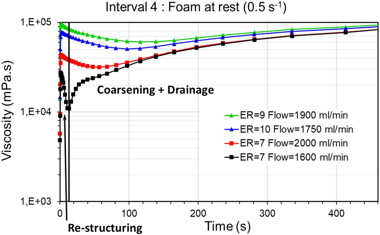
Behavior of foam produced from NNF fluid at rest. Influence of the production rate.
Liquid draining causes continuously changes of the foam structure. When entering the rest situation (starting of interval 4) the foam is still “wet.” For the NF, the restructuring strongly depends on the expansion ratio and the flow rate of the foam feed prior to the immobile interval 4. The viscosity changes can be understood in terms of strain-induced structural rearrangements of the bubbles of still wet foams. In the unsheared foam, diffusion of gas between adjacent bubbles facilitates a coarsening process, whereby the mean bubble size increases slowly with time through an intermittent rearrangement of the foam’s structure. Higher expansion ratios produce more dry films, and consequently, restructuring will be hindered or limited, as the foam dries and stiffens (Figure 8). The observations in this study are similar to earlier reported results [25].
For ER 7, larger transition effects are observed for a lower flow rate of the former foam feed. However, all experiments show coarsening and especially drainage in time, which matches with experiments just focusing on the determination of drainage times using a static set-up, for the foams generated from the NF 5 min and for the foams generated from the NNF 7.5 min. The foams dry quickly and become very stiff. A higher production rate seems to have the same effect as higher expansion ratios.
Testing foam generated by using the NNF shows a slightly different picture (Figure 9). In principle, the same behavior as for NF is present. Restructuring, coarsening, and drainage events can be observed. Due to the higher viscosity of the NNF at rest, which is present in the interlamellar phase of the foam, the structural stability of foams generated from such formulations is higher, and all processes at rest are slower/less pronounced. This applies especially to the restructuring and drainage which is rheologically almost not detectable (Figure 9) and a lot less than for the NF formulation. This clearly indicates a higher stability of foams generated by non-Newtonian foam-forming formulations with improved (delayed) drainage behavior.
With longer rest times, drainage increases and dry foams are formed. Dry gas–liquid foams with gas bubbles at high volume fraction (typically 0.9–0.95) as a result of drainage are tightly-packed soft solids with deformable particles, which are linearly viscoelastic at small shear strains. At large strains, they yield and eventually nonlinear viscoelastic flow occurs. Although foam bubbles are easily deformed, the excess pressure applied in rheometry measurements is negligible compared with the gas pressure in a bubble.
The flow during production of the foam is very important and influences the behavior substantially. High production rates result in more homogenously structured and hence more viscous foams with a smaller intrinsic bubble size and a narrower bubble size distribution due to higher shear stresses inside the static mixer [24]. Such high foam production rates mimic the situation present in an extinguisher best closely; here, deployment rates of 2 l/min are common. Consequently, the foam behavior and hence the experiment is close to reality during the application/use as fire-fighting foam. On the contrary, lower production rates (flow) result in larger bubble sizes and also broader bubble size distributions. After restructuring occurred, coarsening of the bubbles, driven by the great dispersion of bubble size, results in a lowering of the foam viscosity as bubble size would generally increase. Foams with broad bubble size distribution will coarsen into large bubbles, and foam with low bubble size dispersity and small bubbles would not experience much or fast coarsening. Finally, during the third phenomena, viscosity development over time will be different for each foam as the bubble size and bubble size distribution would still be different. It seems that the higher viscosity foams have less drainage (visible with the slight increase of viscosity after a few minutes). The constant foam viscosity over time enables spreading of a foam after application within the time limit given to extinguish a fuel fire (5 min). Also, the measured constant viscosity of the foam indicates the structural stability needed for an efficient sealing of a foam blanket in the envisaged application.
5 Conclusions
The experiments performed with a newly designed measurement cell for foam rheology, which enables constant drainage during measurements and excludes interfering effects such as wall slip phenomena, give insights into the processes happening in 3D during the maturing of a foam. These are distinct from a number of studies in a 2D space with the limitations of wall interference defining the observed area/volume [26,27,28]. Interestingly, improvements in foam viscosity measurements dating back to 1960/1976 were also connected with the study of fire-fighting foams. In this research, the authors introduced steel baffles at the wall of the cup holding the foam sample to prevent sliding along the sides of the cup and paddles, which took the shape of a 6-van cylinder (French, Elliott 2). The experiments performed in our study are more consistent with reality because they maintain a continuous feed of fresh foam and minimize draining and re-structuring processes such as coarsening, etc., for the study of the behavior of foam before measurements were initiated (interval 4 of the performed experiments. With such an experimental set-up, it became possible to study the rheology of foam during different times of an application such as the use in fire-fighting events. Especially the behavior of the foam during application (spraying) as well as the behavior of a foam at rest when the blanket has been formed and acts to separate the flame and air from the fuel were the focus of the experiments. Linking the obtained data to processes such as foam coarsening and coalescence as well as drainage coupled with morphological changes on the bubble scale is not easy since the foam during maturing is constantly changing its morphology and exists in a non-equilibrium state. The new experimental set-up makes a conclusive study of foam in these circumstances possible. As such, rheological fingerprints of process have been established, which are otherwise not possible to observe in a 3D space. This was also possible by carefully designing the experimental protocol and defining distinct intervals of the rheological experiment attributed to the above-mentioned critical periods of the chosen application. Consequently, the goal of the investigation, to link the rheological data measured to the performance of the foam in applications such as fire-fighting foam, was achieved. With such measurements, a judgement of the performance of the foams is possible, and the experiments can function as a tool for the development of better working formulations.
Acknowledgment
We are thankful to Anton Parr for useful suggestions and discussions concerning the design of the foam rheology measurement cell.
-
Funding information: This work was performed within SERDP Contract: W912HQ22C0054 Project Number WP22-3180 “Control of Draining and Flow to Improve Fluorine Free Firefighting Foams” and supported by SERDP.
-
Author contributions: Aubin Puget: investigation, visualization, writing review & editing. Mathilde Piquand: investigation, visualization, writing review & editing. Médric Passedat: investigation, visualization, writing review & editing. Frank vercauteren: methodology, validation, funding acquisition, writing review & editing. Eric Craenmehr: resources, formal analysis, writing review & editing. Joe Trimboli: supervision, writing – review & editing, project administration. Hartmut Fischer: supervision, conceptualization, methodology, writing – original draft.
-
Conflict of interest: Authors state no conflict of interest.
-
Ethical approval: The conducted research is not related to either human or animal use.
-
Data availability statement: The datasets generated during and/or analyzed during the current study are available from the corresponding author on reasonable request.
References
[1] Saint-Jalmes A. Physical chemistry in foam drainage and coarsening. Soft Matter. 2006;2:836–49. 10.1039/B606780H.Search in Google Scholar PubMed
[2] Herzhaft B. Rheology of aqueous foams: A literature review of some experimental works. Rev de l’Inst Francais du Petrole. 2000;54(5):587–96. 10.2516/ogst:1999050.Search in Google Scholar
[3] Dollet B, Raufaste C. Rheology of aqueous foams. C R Phys. 2014;15:731–47. 10.1016/j.crhy.2014.09.008/. https://comptes-rendus.academie-sciences.fr/physique/articles/.Search in Google Scholar
[4] Weaire D. The rheology of foam. Curr Opin Coll Interface Sci. 2008;13(3):171–6. 10.1016/j.cocis.2007.11.004.Search in Google Scholar
[5] Cohen-Addad S, Höhler R, Pitois O. Flow in foams and flowing foams. Ann Rev Fluid Mech. 2013;45:241–67. 10.1146/annurev-fluid-011212-140634.Search in Google Scholar
[6] Höhler R, Cohen-Addad S. Rheology of liquid foam. J Phys Cond Matter. 2005;17(41):R1041–69, https://iopscience.iop.org/article/10.1088/0953-8984/17/41/R01.10.1088/0953-8984/17/41/R01Search in Google Scholar
[7] Calvert JR, Nezhati K. A rheological model for a liquid – gas foam. Int J Heat Fluid Flow. 1986;7:164–8. 10.1016/0142-727X(86)90016-0.Search in Google Scholar
[8] Coussot P. Rheometry of pastes, suspensions, and granular materials: applications in industry and environment. Hoboken, New Jersey: John Wiley & Sons, Inc.; 2005. https://onlinelibrary.wiley.com/doi/book/10.1002/0471720577.10.1002/0471720577Search in Google Scholar
[9] Cohen-Addad S, Höhler R, Khidas Y. Origin of the slow linear viscoelastic response of aqueous foams. Phys Rev Lett. 2004;93:028302-1–4. 10.1103/PhysRevLett.93.028302.Search in Google Scholar PubMed
[10] Yu X, Li H, Kang N, Qiu K, Zong R, Lu S. Enhanced rheology and firefighting performance of fluorine-free soft foams through the assembly of cellulose nanofibres and cellulose nanocrystals at the air–liquid interface. Int J Biol Macrom. 2024;280:136203. 10.1016/j.ijbiomac.2024.136203.Search in Google Scholar PubMed
[11] Zhang S, Sheng Y, Lin X, Ma L, Wang Z, Wang Q, et al. Rheological properties of fluorine-free foams stabilized by aluminum hydroxide nanoparticles and mixture of siloxane and hydrocarbon surfactants. J Mol Liqu. 2024;401:124627. 10.1016/j.molliq.2024.124627.Search in Google Scholar
[12] Sheng Y, Zhang S, Ma W, Peng Y, Ma L, Wang Q, et al. Tuning stability, rheology, and fire-extinguishing performance of advanced firefighting foam material by inorganic nanoparticle flame retardants. J Coll Interf Sci 677:378–89. 10.1016/j.jcis.2024.07.230.Search in Google Scholar PubMed
[13] Koponen AI, Viitala J, Tanaka A, Prakash B, Laukkanen O-V, Jäsberg A. Pipe rheology of wet aqueous application foams. Chem Eng Sci. 2024;283:119282. 10.1016/j.ces.2023.119282.Search in Google Scholar
[14] Gardiner BS, Dlugogorski BZ, Jameson GJ. Rheology of fire-fighting foams. Fire Saf J. 1988;31:61–75. 10.1016/S0379-7112(97)00049-0.Search in Google Scholar
[15] Barnes HA, Nguyen QD. Rotating vane rheometry-a review. J Non-Newtonian Fluid Mech. 2001;98:1–14. 10.1016/S0377-0257(01)00095-7.Search in Google Scholar
[16] Elliott DE, Chiesa Jr PJ. Rheological properties of fire fighting foams. Fire Technol. 1976;12:141–50. 10.1007/BF02629483.Search in Google Scholar
[17] French RJ. Foam viscometer. J Sci Instr. 1960;37:307–8. 10.1088/0950-7671/37/8/123.Search in Google Scholar
[18] Cosset P, Raynaud JS, Bertrand F, Moucheront P, Guilbaud JP, Huynh HT, et al. Coexistence of liquid and solid phases in flowing soft-glassy materials. Phys Rev Lett. 2002;88:218301–4. 10.1103/PhysRevLett.88.218301.Search in Google Scholar PubMed
[19] Burley R, Shakarin M. An experimental study of foam rheology in straight capillary tubes. Int J Eng Fluid Mech. 1992;5(2):115–41.Search in Google Scholar
[20] Enzendorfer C, Harris RA, Valko P, Economides MJ, Fokker PA, Davies DD. Pipe viscometry of foams. J Rheology. 1995;39(2):345–58.10.1122/1.550701Search in Google Scholar
[21] Drenckhan W, Saint-Jalmes A. The science of foaming. Adv Coll Interf Sci. 2015;222:228–59. 10.1016/j.cis.2015.04.001.Search in Google Scholar PubMed
[22] Ransohoff TC, Radke CJ. Mechanisms of foam generation in glass-bead packs. SPE Res Eng. 1988;3:573–85. 10.2118/15441-PA.Search in Google Scholar
[23] Li H, Yu X, Song Y, Li Q, Lu S. Experimental and numerical investigation on optimization of foaming performance of the kenics static mixer in compressed air foam system. Eng Appl Comp Fluid Mech. 2023;17:2183260. 10.1080/19942060.2023.2183260.Search in Google Scholar
[24] Talansier E, Dellavalle D, Loisel C, Desrumaux A, Legrand J. Elaboration of controlled structure foams with the SMX static mixer. AIChE J. 2013;59:132. 10.1002/aic.13796.Search in Google Scholar
[25] Elliott DE, Chiesa Jr PJ. A new foam rheometer for studying fire fighting foams. Fire Techn. 1976;12:66–9. 10.1007/BF02629472.Search in Google Scholar
[26] Katgert G, van Hecke M. Jamming and geometry of two-dimensional foams. EPL. 2010;92:34002. 10.1209/0295-5075/92/34002.Search in Google Scholar
[27] Yanagisawa N, Kurita R. In-situ observation of collective bubble collapse dynamics in a quasi-two-dimensional foam. Sci Rep. 2019;9:5152. 10.1038/s41598-019-41486-6.Search in Google Scholar PubMed PubMed Central
[28] Furuta Y, Oikawa N, Kurita R. Close relationship between a dry-wet transition and a bubble rearrangement in two-dimensional foam. Sci Rep. 2016;6:37506. 10.1038/srep37506.Search in Google Scholar PubMed PubMed Central
© 2025 the author(s), published by De Gruyter
This work is licensed under the Creative Commons Attribution 4.0 International License.
Articles in the same Issue
- Research Articles
- Lie symmetry analysis of bio-nano-slip flow in a conical gap between a rotating disk and cone with Stefan blowing
- Mathematical modelling of MHD hybrid nanofluid flow in a convergent and divergent channel under variable thermal conductivity effect
- Advanced ANN computational procedure for thermal transport prediction in polymer-based ternary radiative Carreau nanofluid with extreme shear rates over bullet surface
- Effects of Ca(OH)2 on mechanical damage and energy evolution characteristics of limestone adsorbed with H2S
- Effect of plasticizer content on the rheological behavior of LTCC casting slurry under large amplitude oscillating shear
- Studying the role of fine materials characteristics on the packing density and rheological properties of blended cement pastes
- Deep learning-based image analysis for confirming segregation in fresh self-consolidating concrete
- MHD Casson nanofluid flow over a three-dimensional exponentially stretching surface with waste discharge concentration: A revised Buongiorno’s model
- Rheological behavior of fire-fighting foams during their application – a new experimental set-up and protocol for foam performance qualification
- Viscoelastic characterization of corn starch paste: (II) The first normal stress difference of a cross-linked waxy corn starch paste
- An innovative rheometric tool to study chemorheology
- Effect of polymer modification on bitumen rheology: A comparative study of bitumens obtained from different sources
- Rheological and irreversibility analysis of ternary nanofluid flow over an inclined radiative MHD cylinder with porous media and couple stress
- Rheological analysis of saliva samples in the context of phonation in ectodermal dysplasia
- Analytical study of the hybrid nanofluid for the porosity flowing through an accelerated plate: Laplace transform for the rheological behavior
- Brief Report
- Correlations for friction factor of Carreau fluids in a laminar tube flow
- Special Issue on the Rheological Properties of Low-carbon Cementitious Materials for Conventional and 3D Printing Applications
- Rheological and mechanical properties of self-compacting concrete with recycled coarse aggregate from the demolition of large panel system buildings
- Effect of the combined use of polyacrylamide and accelerators on the static yield stress evolution of cement paste and its mechanisms
- Special Issue on The rheological test, modeling and numerical simulation of rock material - Part II
- Revealing the interfacial dynamics of Escherichia coli growth and biofilm formation with integrated micro- and macro-scale approaches
- Construction of a model for predicting sensory attributes of cosmetic creams using instrumental parameters based on machine learning
- Effect of flaw inclination angle and crack arrest holes on mechanical behavior and failure mechanism of pre-cracked granite under uniaxial compression
- Special Issue on The rheology of emerging plant-based food systems
- Rheological properties of pea protein melts used for producing meat analogues
- Understanding the large deformation response of paste-like 3D food printing inks
- Seeing the unseen: Laser speckles as a tool for coagulation tracking
- Composition, structure, and interfacial rheological properties of walnut glutelin
- Microstructure and rheology of heated foams stabilized by faba bean isolate and their comparison to egg white foams
- Rheological analysis of swelling food soils for optimized cleaning in plant-based food production
- Multiscale monitoring of oleogels during thermal transition
- Influence of pea protein on alginate gelation behaviour: Implications for plant-based inks in 3D printing
- Observations from capillary and closed cavity rheometry on the apparent flow behavior of a soy protein isolate dough used in meat analogues
- Special Issue on Hydromechanical coupling and rheological mechanism of geomaterials
- Rheological behavior of geopolymer dope solution activated by alkaline activator at different temperature
- Special Issue on Rheology of Petroleum, Bitumen, and Building Materials
- Rheological investigation and optimization of crumb rubber-modified bitumen production conditions in the plant and laboratory