Effects of Ca(OH)2 on mechanical damage and energy evolution characteristics of limestone adsorbed with H2S
-
Yugang Cheng
 ,
Liang Cheng
,
Liang Cheng

Abstract
The occurrence of hydrogen sulfide (H2S) gas gusher accidents is a worrying engineering disaster during tunnel construction travel through stratum adsorbed with H2S. To mitigate the risks associated with H2S, alkaline solutions are applied within the tunnel and injected into the rock mass ahead of the tunnel face to neutralize and eliminate the adsorbed H2S. Samples from the Huangjiagou tunnel in southwestern China are systematically investigated to understand the interaction between H2S-adsorbed limestone and calcium hydroxide (Ca(OH)2) solutions at concentrations of 1, 3, and 5%. The results indicate that exposure of the limestone to Ca(OH)2 solution leads to the erosion of aluminum silicate minerals and the subsequent precipitation of potassium feldspar crystals. The uniaxial compressive strength and modulus of elasticity of the limestone decreased by 48.82 and 28.31%, respectively, following an exponential trend as the concentration of Ca(OH)2 solution increased. Additionally, an increase in the number of abrupt energy changes detected via acoustic emission is observed in limestone treated with higher concentrations of alkaline solutions. Energy evolution analysis indicates that alkaline-treated limestone exhibits significantly enhanced energy dissipation capacity during the loading process, making dissipative energy more likely to dominate.
1 Introduction
With the swift economic growth, the capacity of existing ground transportation infrastructures has often been outpaced by the surge in vehicular numbers, necessitating accelerated infrastructure development, particularly of road and rail tunnels, which are pivotal in easing traffic congestion [1,2,3,4]. However, when encountering coal measures or gas-bearing strata, tunnel construction poses challenges due to the complex and unpredictable geological conditions that can lead to gas gushers and other safety hazards [5,6,7]. Gases typically consist of alkane gases, with trace amounts of non-hydrocarbon gases like hydrogen sulfide (H2S) and carbon dioxide (CO2), which confer hazardous properties such as flammability, toxicity, and asphyxiation risks [8]. H2S, in particular, is a significant toxicant and a threat to human health [9,10]. Current underground engineering, especially in tunneling through coal seams or gas-bearing strata, focuses on controlling gas content, preventing gas gusher incidents, and avoiding gas-induced explosions [11,12,13]. Despite the prevalence of H2S in underground works, a scarcity of research on its management during tunnel construction is highlighted, indicating a need for further exploration and solutions.
H2S-adsorbed formations are globally widespread, with incidents of abnormal H2S emissions reported during construction activities in various regions [14,15]. In China, H2S concentrations as high as 378 ppm were recorded in the Yuelong tunnel in Sichuan Province, and H2S concentrations in the Hongdou Mountain tunnel in Yunnan Province reached 430 ppm, both of which far exceeded the national safety standard of 6.6 ppm. H2S formation typically occurs deep underground under high temperature and pressure, facilitating the chemical reaction of sulfur-bearing minerals or organic substances with alkanes to produce H2S [16,17]. This gas can maintain an adsorption–dissociation equilibrium within the rock’s pores and cracks and can persist for extended periods [18,19]. Additionally, H2S maintains a dissolution–escape balance in groundwater, which can be disrupted by excavation, leading to H2S surges and increased safety risks for underground engineering [20,21,22].
Chinese tunnel engineering has yet to establish specific safety control standards for H2S risks, and current treatment methods, often adapted from mining engineering, include enhancing tunnel ventilation and applying alkaline solutions. However, these measures are often insufficient for managing continuous H2S gas emissions resulting from large-scale formation disturbances during tunneling.
Scholars advocate for the direct injection of alkaline solutions into rock layers as an efficient H2S removal method [23,24]. This approach neutralizes H2S within rock formations and reduces its presence in groundwater, mitigating H2S spill risks. Limestone, common in tunnel engineering and especially in H2S-adsorbed formations, serves as an ideal medium for H2S storage due to its porosity and fracture development [25,26,27,28]. Alkaline solutions injection for H2S neutralization may induce new cracks and pores within the rock or on its surface and can reduce the bonding strength between mineral particles [29,30,31]. Furthermore, secondary precipitates formed by chemical reactions may obstruct original cracks and pores, affecting the mechanical properties and damage evolution of the surrounding rock under external loads [32,33].
This study investigates limestone samples from coal measure strata tunnels that were pre-adsorbed with H2S and subsequently soaked in calcium hydroxide (Ca(OH)2) solution. This research employs a suite of equipment, including an X-ray diffractometer (XRD), gas permeability meter, scanning electron microscope (SEM), multifunctional rock mechanics test system, and an acoustic emission (AE) experiment and acquisition system, to comprehensively analyze changes in sample permeability, mineral composition, mechanical properties, and energy release characteristics during failure. The results of this study provide critical theoretical and data support for analyzing rock’s dynamic mechanical properties under loading, including creep, damage, and the effects of random blasting loads on micro- and macro-scale strength.
2 Material selection and experimental method
2.1 Sample collection and preparation
H2S, a perilous gas often found in conjunction with oil, gas, and coal reserves, is predominantly produced by the conversion of sulfur-containing organic materials under the extreme temperatures and pressures found deep within the Earth’s crust. To replicate the natural presence of H2S within rock formations with precision, this research focuses on limestone samples extracted from the Huangjiagou tunnel, situated in the North Guizhou Plateau of southwestern China. The tunnel runs through a mountainous area characterized by dissolution landforms, classified as middle and low mountain terrain. The terrain is diverse, with gradients ranging from 20° to 55°. The average annual temperature in the construction area ranges from 13 to 18°C. The working environment temperature in the tunnel, influenced by the ground temperature gradient, varies between 17 and 30°C according to field monitoring. Geological exploration, including field investigations, has confirmed the presence of coal measures in the Upper Permian Longtan Formation (P3l), with gas emissions observed during tunnel construction.
This site of sample collection is depicted in Figure 1. To ensure sample uniformity, intact blocky rocks, demonstrating uniformity across the palm surface area, were carefully selected for preparation. In accordance with the Standard of Test Method for Engineering Rock Mass (GB/T 50266-2013), the extracted rock blocks were crafted into two distinct forms: one, a fine powder with particle size finer than 75 μm (200 mesh), was designated for XRD analysis to identify the sample’s mineral constituents; the other, a cylindrical specimen measuring 25 mm in diameter and 50 mm in height, was fashioned for experiments assessing rock mechanics and AE characteristics.
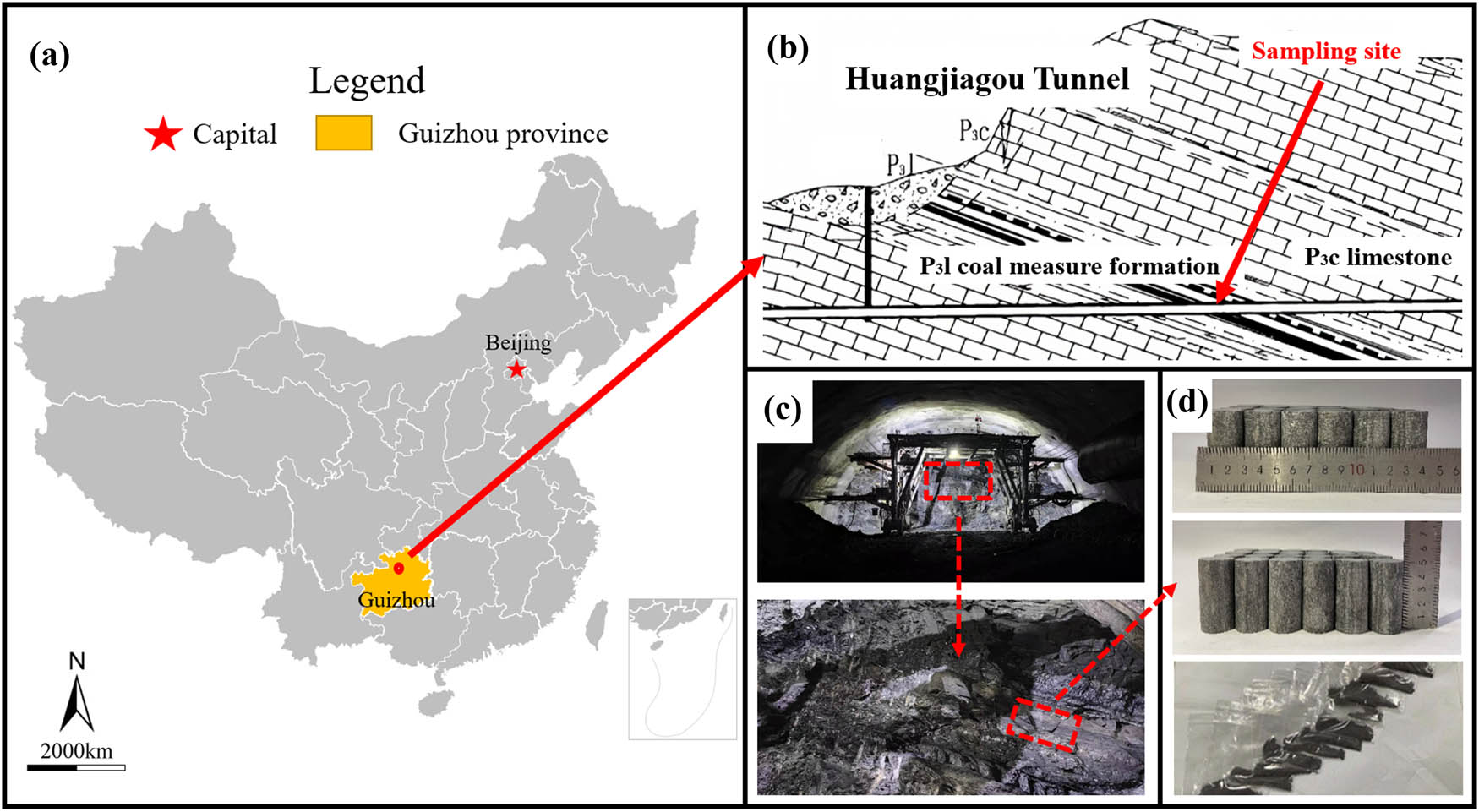
Huangjiagou tunnel sampling site. (a) Location in China, (b) geological schematic of the tunnel s longitudinal section, (c) sampling location at the tunnel working face, and (d) prepared samples.
2.2 Experimental methods
To replicate the natural conditions of H2S-adsorbed rocks and investigate the subsequent alterations in rock damage characteristics following treatment with Ca(OH)2 solution, this study began with H2S adsorption experiments on limestone samples. The experimental parameters for H2S concentration were calibrated using the most severe recorded leakage incident in the tunnel, which peaked at 500 ppm [23]. According to the Coal Mine Safety Regulations amended by China’s Ministry of Emergency Management in 2022, a gas pressure of 0.74 MPa or higher indicates a risk of outburst in the coal (or rock) layer. Based on the safety regulations and the measured ambient temperature in the tunnel, the H2S immersion experiment was performed at a pressure of 1 MPa and a temperature of 26°C. The soaking time for the Ca(OH)2 solution was set to 24 h, in accordance with the 24-h cycle mechanical excavation method used in the construction of the Huangjiagou tunnel, and its effects were evaluated under actual construction conditions.
In the experimental setup, limestone samples were placed in a sealed gas chamber. After evacuation, a mixture of H2S and nitrogen gas was introduced, with the H2S concentration carefully adjusted to 500 ppm through nitrogen dilution. Upon completion of the H2S adsorption phase, the samples were quickly transferred to pre-prepared Ca(OH)2 solutions for immersion. Three distinct concentrations of 1, 3, and 5% were used, with a treatment duration of 24 h.
As illustrated in Figure 2, the experimental setup employed in this study provided the foundation for a series of post-treatment analyses aimed at elucidating the physical and mechanical properties of the limestone samples. Post-treatment, an array of sophisticated analytical techniques was deployed to elucidate the physical and chemical attributes of the limestone samples. The surface morphology was scrutinized and analyzed using a JEOL JSM-7800F field emission scanning electron microscope (FE-SEM), both pre- and post-treatment. A Bruker XRD, equipped with a Cu-Kα radiation source, was engaged to probe the powder samples and ascertain the mineral composition of the limestone. The permeability of the limestone samples was gauged using an AP-608 meter. Mechanical property assessments were executed using the GCTS RTR-1800 rock mechanics test system, which performed a suite of mechanical property tests on the cylindrical specimens to evaluate the strength and deformation characteristics of the limestone. Concurrently, the AE activity of the rocks under load was vigilantly monitored using the PCA Express 8 AE system, offering insights into the rock’s response to mechanical stress.

Experimental system and testing equipment.
3 Experimental results and analysis
3.1 Mineral composition and microscopic characteristics
H2S has a dissolution ratio of 2.6:1 in water and a relatively high solubility [34]. When H2S comes into contact with Ca(OH)2 solution, an acid–base neutralization reaction will occur. H2S dissolves in water to produce binary weak hydrogen acid. Sulfuric acid is continuously consumed by alkaline solutions until it is completely neutralized and absorbed [35,36]. In the alkaline environment provided by Ca(OH)2 solution, H2S molecules are fixed in the form of CaS solids. Specific reactions are shown below [37]:
The neutralization and absorption of adsorbed or free H2S in Ca(OH)2 solution is not instantaneous, but a dynamic and continuous process. H2S dissolved in water produces binary weak acid hydrosulfuric acid and gradually ionizes H+ ions. H+ ions are preferentially neutralized by OH− ions, and there may still be a small amount of H+ ions that come into contact with minerals in the rock and chemically react. After all, H2S is neutralized and absorbed by Ca(OH)2 alkaline solution; the aqueous solution with OH− ions as the main alkaline environment can continue to have physical and chemical interactions with minerals in rocks.
The mineral composition of whole rocks, post-treatment with a range of Ca(OH)2 solution concentrations, is illustrated in Figure 3. By employing XRD analysis, a semi-quantitative technique, we ascertained the proportional makeup of the various minerals present, thereby profiling the mineralogical composition of the rocks. The ionization of H2S in water results in the generation of H+ ions, which predominantly react with carbonate minerals such as calcite (CaCO3) and dolomite (CaMg(CO3)2). Within the alkaline milieu established by Ca(OH)2, dolomite experiences dedolomitization, transforming into calcite [38]. Intriguingly, the concentration of Ca2+ within the solution exerts a substantial influence on the calcite and dolomite content, with elevated Ca2+ levels curtailing the dissolution of these carbonate minerals, a consequence of their aqueous solubility.

Mineral components of limestone under different treatment conditions.
Under alkaline conditions, feldspar minerals display a negative dissolution rate per unit area, signifying a trend toward precipitation. This occurrence is ascribed to the chemical interplay between the alkaline solutions and aluminosilicate minerals, including kaolinite and illite, culminating in the genesis of amorphous aluminosilicate-altered minerals. These amorphous entities, upon integrating with metallic elements suspended in solution, precipitate as feldspar minerals [39]. Moreover, an antagonistic relationship is observed between potassium feldspar and calcium feldspar, characterized by their immiscibility [40,41]. Predominantly, in limestone where feldspar minerals are chiefly potassium feldspar, an induced precipitation process favors potassium feldspar. This intricate interplay of minerals and chemical reactions provides a nuanced perspective on the alterations in rock mineralogy following treatment with Ca(OH)2 solutions, offering insights into the geological and material science implications of such processes.
The possible reactions between Ca(OH)2 and hydrosulfide-bearing limestone minerals [42,43,44] are shown in equations (2)–(5).
Dolomite:
Illite:
Kaolinite:
Feldspar:
This study investigates the impact of alkaline solutions treatment on the microstructure of limestone using FE-SEM. As illustrated in Figure 4, the microstructural comparison of limestone samples before and after Ca(OH)2 treatment reveals significant crystallization and precipitation of potassium feldspar on the rock’s surface. Post-treatment SEM imaging further indicates that these newly formed feldspar crystals were loosely deposited within the pores and cracks.

Corrosion and precipitation phenomena at identical locations on samples before and after treatment with 3% Ca(OH)2 solution. Potassium feldspar crystals precipitated on the rock surface (I, II) accompanied by evident alkali corrosion marks (III, IV, V).
The formation of potassium feldspar deposits is linked to the chemical corrosion of silicate minerals, such as kaolinite and illite, within the limestone. The alkaline environment created by the alkaline solutions treatment leads to the dissolution of these minerals, resulting in the formation of an amorphous aluminosilicate phase. Concurrently, potassium ions are released into the solution. These amorphous aluminosilicates then recombine with the potassium ions, leading to the precipitation of potassium feldspar.
Additionally, SEM images indicated the presence of distinct corrosion marks on the limestone surface, coinciding with the potassium feldspar precipitation. This suggests that the original pore structure of the limestone was not only corroded but also expanded due to the action of the Ca(OH)2 solution.
3.2 Permeability characteristics
In the realm of physics, an escalation in gas permeability within a rock typically signifies an augmentation in the interconnectedness of its pore and fissure network. This enhanced interconnectedness exerts a dual impact on the tunnel’s surrounding rock: First, it aids in bolstering the efficacy of alkaline solutions in controlling H2S emissions, as the improved pore connectivity facilitates the dispersion and infiltration of the alkaline solutions throughout the rock matrix. Second, the permeability uptick is also indicative of the dilation of the rock’s pores and fractures, implying a transition in the rock’s internal architecture from a compact to a more porous state.
Figure 5 delineates the variations in gas phase permeability of limestone samples following treatment with Ca(OH)2 solutions of varying concentrations. The limestone samples exhibited a baseline permeability range of 2.4 × 10⁻¹⁸ m2 to 2.6 × 10⁻¹⁸ m2 prior to their immersion in the Ca(OH)2 solution, attesting to their comparable initial gas phase permeability. Post-treatment, the gas permeability of the limestone samples varied markedly, with the samples treated with a 5% concentration of Ca(OH)2 witnessing the most pronounced increase, soaring to 278.26%.

Permeability changes in limestone before and after Ca(OH)2 treatment. Untreated limestone shows stable permeability, while treatment significantly increases it.
The relationship between the concentration of the alkaline solutions and the gas-phase permeability of limestone samples has demonstrated a strong positive correlation: within the concentration range of 5%, the higher the concentration of the alkaline solutions, the greater the gas-phase permeability of the limestone samples with which it comes into contact. This change indicates that after exposure to Ca(OH)2 solution, the limestone undergoes erosion and develops a more interconnected network of pores and fissures. The rock evolves from a dense state to a more porous condition, with the degree of rock damage increasing rapidly over the same period of time as the concentration of Ca(OH)2 solution increases.
Figure 6 illustrates a schematic representation of the erosion of microscopic limestone particles in an alkaline solution. A comparison of the SEM images of limestone before and after treatment with an alkaline solution reveals that Huangjiagou tunnel limestone contains abundant primary pores in its natural state. In an alkaline solution, OH− ions penetrate the rock through these pore structures, eroding the mineral particles within the limestone and resulting in a loose contact between them. As the concentration of Ca(OH)2 solution increases, more OH− ions occupy the pore structure of the limestone, intensifying the corrosion and dissolution of the cemented material among the mineral particles within the limestone’s microstructure. This process leads to the stripping and loosening of mineral particles. Simultaneously, the potassium feldspar precipitates formed by the alkaline solutions only loosely adhere to the surface of the pore structure, failing to effectively strengthen the rock structure. Therefore, the development and expansion of the pore structure are significantly enhanced as the concentration of alkaline solutions increases, leading to a rapid increase in the looseness of limestone after immersion, resulting in a more permeable and less dense rock state.

Schematic representation of the erosion of limestone in contact with Ca(OH)2 solutions of varying concentrations.
3.3 Mechanical damage characteristics
Complete stress–strain curves are instrumental in characterizing the deformation and failure processes of rocks, providing a comprehensive picture of their mechanical behavior under stress. Figure 7 illustrates the stress–strain curves derived from the outcomes of uniaxial compressive strength tests. The curves reveal that limestone exhibits typical brittle failure characteristics during the deformation and failure process under various treatment conditions.

Stress–strain curves of limestone under different treatment conditions. The red dots denote the complete closure of pores, signifying the onset of the elastic deformation stage.
The interaction between limestone and Ca(OH)2 solution leads to significant alterations in the rock’s microstructure and mechanical properties. This study examines the erosion of limestone upon contact with Ca(OH)2 solution, resulting in the formation of new pores and micro-cracks. Concurrently, the solution reacts with the limestone’s minerals, particularly promoting the precipitation of feldspar minerals, with a notable increase in potassium feldspar content.
The study observes that the void closure point of the limestone, which is the stress–strain level at which internal pores and cracks close under external loads, decreases with increasing concentrations of Ca(OH)2. The stress at the void closure point reduces from an initial 29.91 to 26.31, 22.85, and 21.37 MPa, corresponding to decreases of 12.03, 23.60, and 28.55%, respectively. This trend indicates that the erosion caused by the alkaline solutions treatment enhances the compaction of limestone voids, with the effect intensifying as the alkaline solutions concentration increases, as shown in Figure 8.

Variation characteristics of stress and strain at pore closure point and potassium feldspar content in limestone.
Additionally, the strain at the void closure point also shows a decreasing trend, suggesting that the rock’s response to stress during compaction is altered by the treatment. The relationship between the strain at the void closure point, the potassium feldspar content, and the alkaline solutions concentration is further analyzed, revealing a significant correlation (Figure 8). The increase in potassium feldspar content, attributed to the precipitation from the alkaline solutions mineral reaction, influences the rock’s mechanical behavior. The stress–strain analysis of the compaction stage shows that although the precipitation reaction exceeds the erosion reaction to a certain extent, the precipitated potassium feldspar cannot provide sufficient bearing capacity for the rock. Consequently, the treated limestone compacts at a lower stress level at the void pressure closure point, with a reduced stress variation during this process.
The mechanical properties of limestone samples treated with Ca(OH)2 solution showed a significant decline. Figure 9 shows the changes of peak uniaxial compressive strength and elastic modulus of alkaline solutions concentration in different samples. The results show that the uniaxial compressive strength of limestone is 107.71 MPa before treatment. However, when the samples were soaked with Ca(OH)2 solution at 1, 3, and 5% concentrations, the uniaxial compressive strength decreased to 65.86, 58.33, and 55.13 MPa, respectively, with a decrease ratio of 38.85, 45.85, and 48.82%. In addition, the elastic modulus of the rock also decreases significantly, from 7.11 GPa of the unsoaked sample to 5.91, 6.01, and 5.09 GPa, respectively, by 16.76, 15.35, and 28.31%. By observing the trend of uniaxial compressive strength and elastic modulus with the concentration of Ca(OH)2 solution, we found that the uniaxial compressive strength and elastic modulus decreased significantly with the increase of the concentration of Ca(OH)2 solution, and the decreasing trend showed a significant exponential correlation with the concentration of Ca(OH)2 solution.

Variation characteristics of elastic modulus and compressive strength of limestone with alkaline solutions concentration.
The failure process of brittle rock usually begins with the gradual initiation of cracks under load. With the continuous increase of load, stress concentration will occur at the crack tip. When the maximum allowable stress value at the crack tip exceeds its limit value, the crack will become unstable and expand rapidly. During this process, damage accumulates inside the rock. Finally, under the continuous action of load, crack propagation penetrates the entire rock sample, leading to rock failure [45,46,47]. The compressive strength of limestone decreases more significantly than its elastic mode, which shows that the maximum allowable stress value of the crack tip inside the rock is highly sensitive to the erosion action of Ca(OH)2 solution. The elastic modulus is a key parameter to evaluate the resistance of a material to deformation in the elastic range, while the compressive strength directly reflects the maximum load that a rock can bear. Compared with the trend that the compressive strength changes with the concentration of alkaline solutions, the elastic deformation resistance of limestone decreases slightly. This indicates that the bearing capacity of rock is more affected by the concentration of alkaline solutions than the elastic deformation resistance.
When the Ca(OH)2 solution contacts the limestone, cementing materials such as clay minerals within the rock are rapidly eroded. The originally strong Si–O–Si bond, which bonds clay particles, transforms into the weaker H–O–H bond, leading to a rapid decline in the bonding strength between mineral particles. Under loading conditions, dislocation and slippage are more likely to occur within limestone meso-structures, while micro-cracks formed due to the lack of cementing materials become the dominant fracture paths under stress. As the concentration of alkaline solutions increases from 1 to 3 and 5%, the corrosion effect becomes more pronounced but stabilizes thereafter. This phenomenon can be attributed to a substantial increase in OH− ions within the pore structure; however, the macro-scale pore structure of the rocks, which provides the reaction space for OH− ions, remains largely unchanged, as does the content of aluminosilicate minerals. Only by increasing the concentration of alkaline solutions in pore structure to promote pore development and expansion, the effect on rock deterioration gradually enter the range of marginal decline. Therefore, as the concentration of Ca(OH)2 increases, the decline in rock mechanical properties exhibits a logarithmic trend characterized by an initial rapid decline followed by stabilization.
To delve deeper into the degradation characteristics of limestone under the influence of alkaline solutions, this study compares and analyzes the reduction ratios of uniaxial compressive strength and elastic modulus of limestone with the increased ratio of potassium feldspar (an aluminosilicate mineral), which exhibits the most notable changes among the mineral components. The comparative analysis, as depicted in Figure 10, reveals a strikingly similar pattern between the escalating content of potassium feldspar and the diminishing trends of uniaxial compressive strength and elastic modulus of limestone. Both exhibit a pronounced exponential relationship and a shared characteristic: a rapid initial phase of change that subsequently plateaus. A similar inflection point is observed in this transition, indicating a shift from a rapid decline to a more gradual change.

Trends of elastic modulus and compressive strength of limestone and potassium feldspar content.
These findings underscore the pivotal role of aluminosilicate mineral content in influencing the compressive strength and elastic modulus of hydrosulfide limestone following its immersion in a Ca(OH)2 solution. The degradation of limestone’s mechanical properties appears to be closely linked to the transformation and reactivity of its aluminosilicate minerals, particularly potassium feldspar, in response to alkaline solutions treatment.
3.4 AE characteristics of limestone
Figure 11 presents the AE ringing number, cumulative AE ringing number, and stress–time curves for limestone samples immersed in varying concentrations of alkaline solutions. This data indicates that the AE activity follows a comparable pattern across different conditions, whether the limestone has been treated with alkaline solutions or not. Typically, the ringing count is relatively low, but it significantly escalates at the threshold of the rock’s ultimate stress capacity, where both the frequency and intensity of acoustic vibrations peak. Moreover, during interruptions in stress, there is an instantaneous increase in the frequency and amplitude of the ringing counts.

AE characteristics of limestone at different Ca(OH)2 concentrations. (a) Untreated, (b) 1% solution, (c) 3% solution, and (d) 5% solution.
Limestone samples that have been soaked in alkaline solutions exhibit substantial AE events during the fracture closure phase, a phenomenon not as pronounced in untreated samples. The alkaline erosion affects the rock’s primary minerals and cementing materials, compromising the rock’s structural integrity and gradually damaging the rock skeleton. This damage results in a decline in the strength of the rock’s skeletal elements and a reduced capacity to resist deformation. As the pores and micro-cracks in the alkaline solutions treated limestone close, significant damage and destruction occur, accompanied by a multitude of substantial AE events.
Furthermore, prior to treatment with Ca(OH)2, the frequency of AE events in limestone samples is minimal during the initial elastic fracture stage, with a slow increase in the cumulative AE count. The number of AE events does not surge until the limestone reaches the stable fracture expansion phase under stress. In contrast, treated samples, due to the damage to the rock skeleton’s internal structure from alkaline erosion, experience rapid crack initiation and transition into a stable expansion state under external loads. Throughout this process, the cumulative AE count escalates sharply, reaching its peak as the samples enter the failure stage.
Figure 11 illustrates that the patterns of AE energy variation in limestone are fundamentally consistent across different conditions. Typically, the release of AE energy is relatively low. However, it reaches a peak near the rock’s maximum stress value. Additionally, there is an instantaneous surge in energy release during moments of stress discontinuity. An increase in the concentration of alkaline solutions in which the samples are immersed correlates with a decrease in rock strength and an increase in the amount of energy released. Throughout the loading process, there are multiple regions where there is an abrupt release of absolute energy, aligning with the timing and progression of the primary fracture surface’s formation. Broadly, the higher the relative displacement rate of the main fracture plane, the greater the energy released. The relative displacement rate of the main fracture surface gradually decreases over the entire fracturing process, indicating that the alkaline solutions treatment reduces the sample’s energy retention capacity, thereby lessening the intensity of deformation and failure.
The cumulative AE event count curve for treated limestone exhibits a “continuous accumulation rise,” in contrast to the “multi-step rise” pattern observed in untreated limestone. This divergence suggests that in untreated limestone, energy accumulates and stores under external loading, with a low frequency of energy dissipation and release before the crack extends to a critical state. Conversely, when rock samples are subjected to alkaline solutions, the internal energy of the rock is accompanied by substantial energy dissipation and release as it loads, weakening the rock’s resistance to deformation and making it more susceptible to damage.
In summary, the AE monitoring provides a clear indication of the internal changes within limestone samples due to alkaline solutions treatment, highlighting the progressive weakening of the rock’s structural integrity and its increased propensity for damage under load.
4 Evolution law of limestone damage and destruction energy
4.1 Characteristics of energy change
The deformation and failure process of rock is accompanied by energy absorption, accumulation, dissipation, and release. Part of the total energy (U) absorbed by the limestone during loading is converted into elastic strain energy (U e) and stored in the rock, while the other part is dissipated as dissipated energy (U d) in the form of micro-crack propagation and plastic deformation during deformation. The energy conversion of sample deformation and failure is a dynamic process, and its conversion relationship is as follows [48]:
where U, U e, and U d represent the total absorbed energy, elastic strain energy, and dissipated energy (MJ m−3) of the rock, respectively.
In the context of uniaxial compression, only the axial force performs work, while the external force induces deformation in the rock mass element. Assuming no heat exchange occurs between the process and the external environment, the total input strain energy resulting from external work can be fully absorbed by the rock. The total absorbed energy U and the elastic strain energy U e can be expressed as follows [49,50]:
where σ and ε represent the axial stress and strain of limestone, respectively; σ i and ε i denote the stress and strain values corresponding to each point on the axial stress–strain curve
where E is the elastic modulus.
Through the stress–strain curves of rock samples, the internal energy characteristic curves of rock under different treatments can be calculated.
Figure 12 shows the variation characteristics of total absorbed energy (U), elastic strain energy (U e), and dissipated energy (U d) of limestone during loading. Limestone soaked without Ca(OH)2 solution can absorb and carry more energy when subjected to external loads. The main reason for this difference is the erosion damage caused by alkaline solutions treatment to the internal structure of limestone. In particular, as one of the main components of the rock, the proportion of the mineral composition of the aluminosilicate minerals has changed greatly, which means that the minerals inside the rock have produced a large number of chemical reactions. These reactions lead to the weakening of the cementation between mineral particles inside the rock, resulting in the weakening of the structure and the reduction of the deformation resistance of the rock. During the loading process, the elastic deformation ability of limestone is weakened, and the storage and accumulation capacity of elastic strain energy (U e) is decreased. The peak elastic strain energy (U e) of limestone under untreated conditions decreased from 0.78 to 0.29, 0.23, and 0.20 MJ m3, and the decreases reached 62.82, 70.51, and 74.34%. Alkaline solution erosion has significant effects on the total absorbed energy (U) and elastic strain energy (U e) of rock samples, indicating that treated limestone dissipates more energy in the deformation stage before brittle failure, and the dissipative properties of the rock are enhanced. This shows that the rock samples treated with alkaline solutions are more prone to crack initiation and development during loading. At the stage of compaction and elastic deformation, the soaked limestone samples exhibit stronger energy dissipation characteristics. With the continuous action of external loads, rocks enter the stage of stable crack expansion, at which the difference of dissipated energy (U d) is more obvious, and cracks and failures are more likely to occur under the action of loads.

Energy variation of limestone at different Ca(OH)2 concentrations. (a) Untreated, (b) 1% solution, (c) 3% solution, and (d) 5% solution.
4.2 Analysis of damage evolution process
The ratio of elastic energy and dissipated energy to total energy is an important parameter to reflect the law of energy transformation in the deformation process of rock. Figure 13 shows the proportional changes of elastic properties and dissipated energy of rock during uniaxial compression under four different treatment conditions, as well as the evolution curve of damage variables based on energy dissipation, so as to further observe the energy state and damage behavior of rock during the mechanical response process of rock.

Energy partitioning evolution of limestone at different Ca(OH)2 concentrations. (a) Untreated, (b) 1% solution, (c) 3% solution, and (d) 5% solution. U e/U and U d/U denote the proportions of elastic strain energy and dissipated energy to the total energy, respectively, while U e/U eMax represents the normalized ratio of dissipated energy to its maximum value.
The analysis results in Figure 13 show a high degree of consistency in the patterns of energy evolution in the rock samples under all treatment conditions. The ratio of dissipated energy to total absorbed energy showed a trend of rapid decline after a short increase in the initial stage. This is because in the initial compaction stage of the rock, the closure of the internal void leads to greater deformation than the deformation of the rock skeleton, and the energy dissipation in the rock is mainly due to the closure of cracks and pores. When the proportion curve of dissipated energy reaches its peak, its value begins to decrease linearly, while the proportion curve of elastic strain energy increases linearly. Nevertheless, the proportion of dissipated energy in the early stage is still higher than the proportion of elastic energy. This indicates that the compaction of the initial void inside the rock, the friction energy dissipation between mineral particles, and the initiation of new cracks dominate the initial deformation stage under uniaxial loading. At the same time, the elastic deformation of the rock matrix continues, resulting in the accumulation of elastic strain energy. With the continuous increase of external load, the elastic strain energy ratio curve tends to be gentle after rising for a period, and the elastic deformation of the rock skeleton approaches its limit state. Eventually, when the rock reaches its limit of strength and failure occurs, the energy previously stored inside the rock is rapidly released, and the dissipated energy reaches its peak.
The intersection of the dissipative energy ratio curve and the elastic strain energy ratio curve marks the transformation of pore crack development and elastic deformation dominance in rock. After this junction, the energy conversion properties of the rocks begin to change. The specific stress–strain behavior of limestone at the characteristic energy transformation point is shown in Figure 14. For alkaline solutions treated limestone, with the increase of alkaline solutions concentration, the intersection point shifts to a higher external load, indicating that the limestone needs more external energy input when it reaches the equilibrium state of dissipative energy and elastic strain energy.

Stress–strain behavior of limestone at the characteristic energy transformation point. With increasing alkaline solutions concentration and dominance of elastic strain energy (exceeding 50%), higher stress and strain levels are required for deformation.
Further analysis of the stress–strain relationship between the concentration of alkaline solutions and the stress–strain value at the energy transition point shows that there is an obvious linear correlation between the concentration of alkaline solutions and the stress–strain value at the energy transition point. This shows that in the range of Ca(OH)2 concentration ≤5%, with the increase of alkaline solutions concentration, the energy dissipation characteristics of limestone are enhanced, and more of the total absorbed energy is converted to the dissipation of cracks in the rock, rather than being stored as elastic strain energy. This phenomenon shows that the energy release rate and damage evolution rate of the alkaline solutions treated limestone increase significantly with the increase of alkaline solutions concentration.
5 Conclusion
Upon immersion in a Ca(OH)2 solution, the limestone undergoes a marked transformation in both its internal structure and mechanical properties. Alkaline erosion within the rock’s core leads to the degradation of aluminosilicate minerals and the formation of secondary potassium feldspar precipitates. This process results in the expansion of the limestone’s pre-existing pores and fissures, significantly enhancing its permeability. Concurrently, the newly formed precipitates decrease the strain size of the rocks during compaction. As the concentration of the alkaline solutions increases, the variation in potassium feldspar content is observed to correlate with the changes in uniaxial compressive strength and elastic modulus of limestone. The interaction between H2S-adsorbed limestone and Ca(OH)2 solution is crucial, as the chemical reactions involving aluminosilicate minerals play a key role in the deterioration of the rock’s mechanical integrity.
After exposure to a Ca(OH)2 solution, a significant decline is experienced by the uniaxial compressive strength and elastic modulus of limestone. Upon elevating the concentration of the alkaline solutions to 5%, a substantial reduction in these properties is observed, with the uniaxial compressive strength and elastic modulus plummeting by 48.82 and 28.31%, respectively. This substantial decrease underscores the pronounced detrimental impact of the alkaline solutions on limestone. AE characteristic analysis reveals that limestone subjected to Ca(OH)2 solution treatment exhibits notable AE activity during the compression phase. During the elastic deformation phase, the limestone that has been treated exhibits an inclination toward the initiation and progression of cracks, with an increase in the regions of abrupt AE energy changes. Notably, limestone samples treated with a 5% concentration of Ca(OH)2 solution have demonstrated a propensity for crack propagation even during the elastic deformation phase.
During the loading process, energy in limestone treated with an alkaline solution is predominantly expended and released through the initiation and propagation of fractures, rather than being conserved. This results in a markedly enhanced capacity for energy dissipation. In limestone that has been treated with a Ca(OH)2 solution, the phase where dissipative energy is predominant is extended, and this effect intensifies with increasing alkaline solution concentration. This observation indicates that as the concentration of the alkaline solutions rises, greater damage is sustained by the internal structure of the limestone and more pronounced crack development is experienced.
Acknowledgments
Thanks to Chongqing Yuyue Action and CSC program.
-
Funding information: This work was supported by the Excellent Youth Foundation of Chongqing Scientific Committee (CSTB2024NSCQ-JQX0001), Chongqing Municipal Natural Science Foundation (CSTB2023NSCQ-MSX0854), Chongqing Municipal Transportation Science and Technology Project (2022-03), National Natural Science Foundation of China (grant No. 52204087), Yunnan Fundamental Research Projects (Grant No. 202401AT070406), and Yunnan Fundamental Research Projects (Grant No. 202101BE070001-039).
-
Author contributions: All authors have accepted responsibility for the entire content of this manuscript and consented to its submission to the journal, reviewed all the results and approved the final version of the manuscript. Yugang Cheng and Mengru Zeng designed and conducted the experiments and contributed to writing, reviewing, and editing. Jinjie Yang was responsible for methodology development, data curation, and manuscript drafting. Liang Cheng and Xuefu Zhang contributed to data analysis and supervision, while Yong Hao, Bo Hu, and Xidong Du were responsible for interpretation and supervision. The manuscript was prepared by Mengru Zeng with contributions from all co-authors.
-
Conflict of interest: Authors state no conflict of interest.
-
Ethical approval: The conducted research is not related to either human or animal use.
-
Data availability statement: All data generated or analyzed during this study are included in this published article.
References
[1] Byun GW, Kim DG, Lee SD. Behavior of the ground in rectangularly crossed area due to tunnel excavation under the existing tunnel. Tunn Undergr SP Tech. 2006;21(3):361. 10.1016/j.tust.2005.12.178.Search in Google Scholar
[2] Shi W, Hong ZL, Yang M, Li N, Tan TX. Impact of subway shield tunnel construction on deformation of existing utility tunnel. Front Earth SC-Switz. 2023;11:1104865. 10.3389/feart.2023.1104865.Search in Google Scholar
[3] Fang Q, Zhang DL, Li QQ, Wong LNY. Effects of twin tunnels construction beneath existing shield-driven twin tunnels. Tunn Undergr SP Tech. 2015;45:128–37. 10.1016/j.tust.2014.10.001.Search in Google Scholar
[4] Sheng ESY, Chuan JYT, Ikhyung HK, Osborne NH, Boon CK, Siew R. Tunnelling undercrossing existing live MRT tunnels. Tunn Undergr SP Tech. 2016;57:241–56. 10.1016/j.tust.2016.02.013.Search in Google Scholar
[5] Yan Q, Yang K, Wu W, Wang F, He FS. Prevention and control of gas hazards in a tunnel under construction: a case study. Environ Earth Sci. 2020;79:1–17. 10.1007/s12665-020-09065-5.Search in Google Scholar
[6] Qi TY, Lei B, Wang R, Li Y, Li ZY. Solid-fluid-gas coupling prediction of harmful gas eruption in shield tunneling. Tunn Undergr SP Tech. 2018;71:126–37. 10.1016/j.tust.2017.08.014.Search in Google Scholar
[7] Kang XB, Xu M, Luo S, Xia Q. Study on formation mechanism of gas tunnel in non-coal strata. Nat Hazards. 2013;66:291–301. 10.1007/s11069-012-0484-y.Search in Google Scholar
[8] Faramawy S, Zaki T, Sakr AAE. Natural gas origin, composition, and processing: A review. J Nat Gas Sci Eng. 2016;34:34–54. 10.1016/j.jngse.2016.06.030.Search in Google Scholar
[9] Maie N, Anzai S, Tokai K, Kakino W, Taruya H, Ninomiya H. Using oxygen/ozone nanobubbles for in situ oxidation of dissolved hydrogen sulfide at a residential tunnel-construction site. J Environ Manage. 2022;302:114068. 10.1016/j.jenvman.2021.114068.Search in Google Scholar PubMed
[10] Liu M, Deng Q, Zhao F, Liu YW. Origin of hydrogen sulfide in coal seams in China. Saf Sci. 2012;50(4):668–73. 10.1016/j.ssci.2011.08.054.Search in Google Scholar
[11] Aguado MBD, Nicieza CG. Control and prevention of gas outbursts in coal mines, Riosa–Olloniego coalfield, Spain. Int J Coal Geol. 2007;69(4):253–66. 10.1016/j.coal.2006.05.004.Search in Google Scholar
[12] Copur H, Cinar M, Okten G, Bilgin N. A case study on the methane explosion in the excavation chamber of an EPB-TBM and lessons learnt including some recent accidents. Tunn Undergr SP Tech. 2012;27(1):159–67. 10.1016/j.tust.2011.06.009.Search in Google Scholar
[13] Fan C, Li S, Luo M, Du W, Yang Z. Coal and gas outburst dynamic system. Int J Min Sci Technol. 2017;27(1):49–55. 10.1016/j.ijmst.2016.11.003.Search in Google Scholar
[14] Belenitskaya GA. Distribution pattern of hydrogen sulphide-bearing gas in the former Soviet Union. Pet Geosci. 2000;6(2):175–87. 10.1144/petgeo.6.2.175.Search in Google Scholar
[15] Aali J, Rahimpour-Bonab H, Kamali MR. Geochemistry and origin of the world’s largest gas field from Persian Gulf, Iran. J Pet Sci Eng. 2006;50(3–4):161–75. 10.1016/j.petrol.2005.12.004.Search in Google Scholar
[16] Xie WD, Wang H, Wang M, He Y. Genesis, controls and risk prediction of H2S in coal mine gas. Sci Rep-UK. 2021;11(1):5712. 10.1038/s41598-021-85263-w.Search in Google Scholar PubMed PubMed Central
[17] Wang Z, Zhou N, Lu S, Liu Y, Liu L, Liu Y, et al. Generation, accumulation, and distribution of Upper Paleozoic tight sandstone gas in the northeastern margin of the Ordos Basin. Mar Pet Geol. 2023;156:106463. 10.1016/j.marpetgeo.2023.106463.Search in Google Scholar
[18] Deng Q, Wei J, Li H, Wang Y, Wu X, Liu M. Hydrogen sulfide accumulation factors in coal mine of southeastern margin of Junggar basin in China. Appl Ecol Environ Res. 2019;17(1):683–97. 10.15666/aeer/1701_683697.Search in Google Scholar
[19] Yao H, Gao F, Yu S, Dang W. Construction risks of Huaying mount tunnel and countermeasures. Front Struct Civ Eng. 2017;11:279–85. 10.1007/s11709-017-0414-x.Search in Google Scholar
[20] Khave GJ. Delineating subterranean water conduits using hydraulic testing and machine performance parameters in TBM tunnel post-grouting. Int J Rock Mech Min. 2014;70:308–17. 10.1016/j.ijrmms.2014.04.013.Search in Google Scholar
[21] Ahmadi MH, Hekmat MH. Numerical and experimental investigation of air flow behavior and H2S gas emission through an inclined traversed tunnel. J Braz Soc Mech Sci. 2021;43:1–15. 10.1007/s40430-021-03173-4.Search in Google Scholar
[22] Mooyaart EAQ, Gelderman ELG, Nijsten MW, de Vos R, Hirner JM, de Lange DW, et al. Outcome after hydrogen sulphide intoxication. Resuscitation. 2016;103:1–6. 10.1016/j.resuscitation.2016.03.012.Search in Google Scholar PubMed
[23] Cheng Y, Zhang X, Du X, Yang F, Hu B, Xiao S, et al. Microstructural changes in limestone after treatment with Na2CO3 solution: Implications for eliminating H2S in tunnels. Arab J Chem. 2022;15(12):104320. 10.1016/j.arabjc.2022.104320.Search in Google Scholar
[24] Fan K, Shen Y, Gao B, Zhou P, Zheng Q, Wang S. Rich hydrogen sulfide tunnel alkali solid sulfur injection mechanism and numerical simulation. China J Highw Transp. 2019;32(8):145–55. 10.19721/j.carol carroll nki.1001-7372.2019.08.013. (In Chinese).Search in Google Scholar
[25] Lee S, Moon JS. Excessive groundwater inflow during TBM tunneling in limestone formation. Tunn Undergr SP Tech. 2020;96:103217. 10.1016/j.tust.2019.103217.Search in Google Scholar
[26] Martínez-Ibáñez V, Garrido ME, Signes CH, Tomás R. Micro and macro-structural effects of high temperatures in Prada limestone: Key factors for future fire-intervention protocols in Tres Ponts Tunnel (Spain). Constr Build Mater. 2021;286:122960. 10.1016/j.conbuildmat.2021.122960.Search in Google Scholar
[27] Andreetto F, Dela Pierre F, Gibert L, Natalicchio M, Ferrando S. Potential fossilized sulfide-oxidizing bacteria in the upper Miocene sulfur-bearing limestones from the Lorca Basin (SE Spain): Paleoenvironmental implications. Front Microbiol. 2019;10:1031. 10.3389/fmicb.2019.01031.Search in Google Scholar PubMed PubMed Central
[28] Duda R, Bilkiewicz E, Becker R. Hydrogen sulphide (H2S) migration in groundwater of the Zechstein strata in the Legnica-Głogów Copper Basin and its vicinity, SW Poland. Geol Q. 2020;67:39. 10.7306/gq.1709.Search in Google Scholar
[29] Kazempour M, Sundstrom E, Alvarado V. Geochemical modeling and experimental evaluation of high-pH floods: Impact of water-rock interactions in sandstone. Fuel. 2012;92(1):216–30. 10.1016/j.fuel.2011.07.022.Search in Google Scholar
[30] Liu Y, He B, Dai F, Zhang Q, Liu Y. Mechanical responses of chemically corroded sandstone under cyclic disturbance: Insights from fatigue properties and macro-micro fracturing mechanism. Int J Rock Mech Min. 2024;180:105818. 10.1016/j.ijrmms.2024.105818.Search in Google Scholar
[31] Zhang X, Wang Q, Fang J, Huang H, Zhang K. Macroscopic mechanical and microscopic characteristics variations of red sandstone from Qinghai Province with solution erosion. B Eng Geol Environ. 2024;83(8):339. 10.1007/s10064-024-03838-z.Search in Google Scholar
[32] Zhang N, Wang H, Wang S, Wang S, Guo Y, Xun X. Study on the evolution law of pore structure and mechanical properties of mudstone under the effect of water-rock chemistry. J Porous Media. 2023;26(12):1–12. 10.1615/JPorMedia.2023047050.Search in Google Scholar
[33] Cheng Y, Zeng M, Lu Z, Du X, Yin H, Yang L. Effects of supercritical CO2 treatment temperatures on mineral composition, pore structure and functional groups of shale: implications for CO2 sequestration. Sustainability-Basel. 2020;12(9):3927. 10.3390/su12093927.Search in Google Scholar
[34] Clarke ECW, Glew DN. Aqueous nonelectrolyte solutions. Part VIII. Deuterium and hydrogen sulfides solubilities in deuterium oxide and water. J Chem-NY. 1971;49(5):691–8. 10.1139/v71-116.Search in Google Scholar
[35] Molnar E, Rippel-Pethő D, Horvath G, Bobek J, Bocsi R, Hodai Z. Removal of hydrogen sulphide content from biogas by atomizing of alkali solution. Stud Univ Babes-Bolyai Chem. 2017;62(3):265–72. 10.24193/subbchem.2017.3.22.Search in Google Scholar
[36] Molnar E, Rippel-Petho D, Horvath G, Bobek J, Bocsi R, Hodai Z. Study of selective hydrogen sulfide absorption by comparing two different alkali absorbents by using atomization method. Stud Univ Babes Bolyai Chem. 2017;62(3):273–82. 10.24193/subbchem.2017.3.23.Search in Google Scholar
[37] Tippayawong N, Thanompongchart P. Biogas quality upgrade by simultaneous removal of CO2 and H2S in a packed column reactor. Energy. 2010;35(12):4531–5. 10.1016/j.energy.2010.04.014.Search in Google Scholar
[38] Arabi N, Jauberthie R, Chelghoum N, Molez L. Formation of CSH in calcium hydroxide–blast furnace slag–quartz–water system in autoclaving conditions. Adv Cem Res. 2015;27(3):153–62. 10.1680/adcr.13.00069.Search in Google Scholar
[39] Różycka A, Kotwica Ł. Effect of alkali on the synthesis of single phase gyrolite in the system CaO-Quartz-H2O. Constr Build Mater. 2020;239:117799. 10.1016/j.conbuildmat.2019.117799.Search in Google Scholar
[40] Liu C, Ma H. Hydrothermal decomposition process of K‐feldspar in NaOH solution. Asia‐Pac J Chem Eng. 2021;16(1):e2578. 10.1002/apj.2578.Search in Google Scholar
[41] Yuan B, Li C, Liang B, Lu L, Yue HR, Sheng HY, et al. Extraction of potassium from K-feldspar via the CaCl2 calcination route. Chin J Chem Eng. 2015;23(9):1557–64. 10.1016/j.cjche.2015.06.012.Search in Google Scholar
[42] Asano T, Kawasaki T, Higuchi N, Horikawa Y. Feasibility study of solidification for low-level liquid waste generated by sulfuric acid elution treatment of spent ion exchange resin. J Power Energy Syst. 2008;2(1):206–14. 10.1299/jpes.2.206.Search in Google Scholar
[43] Fernández R, Ruiz AI, Cuevas J. The role of smectite composition on the hyperalkaline alteration of bentonite. Appl Clay Sci. 2014;95:83–94. 10.1016/j.clay.2014.03.015.Search in Google Scholar
[44] Harrou A, Lechheb M, El Ouahabi M, Fagel N, Gharibi E. Physico-chemical properties and microstructure of bentonite in highly alkaline environments. Clay Clay Mine. 2024;72:e15. 10.1017/cmn.2024.27.Search in Google Scholar
[45] Gao W, Dai S, Xiao T, He TY. Failure process of rock slopes with cracks based on the fracture mechanics method. Eng Geol. 2017;231:190–9. 10.1016/j.enggeo.2017.10.020.Search in Google Scholar
[46] Liu L, Li H, Li X. A state-of-the-art review of mechanical characteristics and cracking processes of pre-cracked rocks under quasi-static compression. J Rock Mech Geotech. 2022;14(6):2034–57. 10.1016/j.jrmge.2022.03.013.Search in Google Scholar
[47] Öge İF, Erkayaoğlu M. Pre-and post-failure characterisation of low-strength rocks by generalised crack initiation and crack damage. B Eng Geol Environ. 2024;83(3):91. 10.1007/s10064-024-03585-1.Search in Google Scholar
[48] Xie HP, Li LY, Ju Y, Peng RD, Yang YM. Energy analysis for damage and catastrophic failure of rocks. Sci China Technol Sci. 2011;54:199–209. 10.1007/s11431-011-4639-y.Search in Google Scholar
[49] Gong FQ, Yan JY, Luo S, Li XB. Investigation on the linear energy storage and dissipation laws of rock materials under uniaxial compression. Rock Mech Rock Eng. 2019;52:4237–55. 10.1007/s00603-019-01842-4.Search in Google Scholar
[50] Xu Q, Tian AR, Luo XY, Liao X, Tang Q. Chemical damage constitutive model establishment and the energy analysis of rocks under water–rock interaction. Energies. 2022;15(24):9386. 10.3390/en15249386.Search in Google Scholar
© 2025 the author(s), published by De Gruyter
This work is licensed under the Creative Commons Attribution 4.0 International License.
Articles in the same Issue
- Research Articles
- Lie symmetry analysis of bio-nano-slip flow in a conical gap between a rotating disk and cone with Stefan blowing
- Mathematical modelling of MHD hybrid nanofluid flow in a convergent and divergent channel under variable thermal conductivity effect
- Advanced ANN computational procedure for thermal transport prediction in polymer-based ternary radiative Carreau nanofluid with extreme shear rates over bullet surface
- Effects of Ca(OH)2 on mechanical damage and energy evolution characteristics of limestone adsorbed with H2S
- Effect of plasticizer content on the rheological behavior of LTCC casting slurry under large amplitude oscillating shear
- Studying the role of fine materials characteristics on the packing density and rheological properties of blended cement pastes
- Deep learning-based image analysis for confirming segregation in fresh self-consolidating concrete
- MHD Casson nanofluid flow over a three-dimensional exponentially stretching surface with waste discharge concentration: A revised Buongiorno’s model
- Rheological behavior of fire-fighting foams during their application – a new experimental set-up and protocol for foam performance qualification
- Viscoelastic characterization of corn starch paste: (II) The first normal stress difference of a cross-linked waxy corn starch paste
- An innovative rheometric tool to study chemorheology
- Effect of polymer modification on bitumen rheology: A comparative study of bitumens obtained from different sources
- Rheological and irreversibility analysis of ternary nanofluid flow over an inclined radiative MHD cylinder with porous media and couple stress
- Rheological analysis of saliva samples in the context of phonation in ectodermal dysplasia
- Analytical study of the hybrid nanofluid for the porosity flowing through an accelerated plate: Laplace transform for the rheological behavior
- Brief Report
- Correlations for friction factor of Carreau fluids in a laminar tube flow
- Special Issue on the Rheological Properties of Low-carbon Cementitious Materials for Conventional and 3D Printing Applications
- Rheological and mechanical properties of self-compacting concrete with recycled coarse aggregate from the demolition of large panel system buildings
- Effect of the combined use of polyacrylamide and accelerators on the static yield stress evolution of cement paste and its mechanisms
- Special Issue on The rheological test, modeling and numerical simulation of rock material - Part II
- Revealing the interfacial dynamics of Escherichia coli growth and biofilm formation with integrated micro- and macro-scale approaches
- Construction of a model for predicting sensory attributes of cosmetic creams using instrumental parameters based on machine learning
- Effect of flaw inclination angle and crack arrest holes on mechanical behavior and failure mechanism of pre-cracked granite under uniaxial compression
- Special Issue on The rheology of emerging plant-based food systems
- Rheological properties of pea protein melts used for producing meat analogues
- Understanding the large deformation response of paste-like 3D food printing inks
- Seeing the unseen: Laser speckles as a tool for coagulation tracking
- Composition, structure, and interfacial rheological properties of walnut glutelin
- Microstructure and rheology of heated foams stabilized by faba bean isolate and their comparison to egg white foams
- Rheological analysis of swelling food soils for optimized cleaning in plant-based food production
- Multiscale monitoring of oleogels during thermal transition
- Influence of pea protein on alginate gelation behaviour: Implications for plant-based inks in 3D printing
- Observations from capillary and closed cavity rheometry on the apparent flow behavior of a soy protein isolate dough used in meat analogues
- Special Issue on Hydromechanical coupling and rheological mechanism of geomaterials
- Rheological behavior of geopolymer dope solution activated by alkaline activator at different temperature
- Special Issue on Rheology of Petroleum, Bitumen, and Building Materials
- Rheological investigation and optimization of crumb rubber-modified bitumen production conditions in the plant and laboratory