Study on bending performance of prefabricated glulam-cross laminated timber composite floor
-
Hao Du


Abstract
The glulam-cross laminated timber (CLT) composite floor is a type of prefabricated composite floor that integrates glulam beams and CLT slab into a unified structure using shear connectors. To investigate the bending performance of the glulam-CLT composite floor, the bending test was conducted on a full-scale composite floor under static load. The study comprehensively analyzed the failure mechanism, load–deflection behavior, interface slip and strain distribution of the glulam-CLT composite floor. The test results of the composite floor indicated that the failure mode was tensile fracture of the wood beam at the bottom. As the load increased, the deflection deformation of the mid-span beam exceeded that of the edge beam. When the load reached its ultimate limit, the deflection deformation of the mid-span beam increased by 14.4% compared to the edge beam. In the early loading phase, the strain distribution of the composite section satisfied the assumption of a plane section. However, the strain distribution deviated from this assumption with the increased load due to the relative slips between the glulam beam and CLT flange. To calculate the bending performance of the composite floor, the M-shaped section of the glulam-CLT composite floor was simplified as T-section composite beams. The linear-elastic method for determining the flexural rigidity and ultimate bearing capacity of the glulam-CLT composite floors was proved to be accurate and reliable. The findings provided valuable insights into the bending behavior of the CLT flange under load and emphasized the non-uniform stress distribution caused by shear lag effects.
1 Introduction
Wood is a typical environmentally friendly and sustainable building material. Wood products have made significant progress with the development of processing techniques, demonstrating further advantages in seismic resistance, preservation, and structural performance [1,2,3]. Wood structures have been widely applied in commercial buildings, residential constructions, and high-rise buildings [4,5,6]. For the large-span and high-strength components, the traditional wood lumbers were difficult to meet design requirements. Glulam is achieved by recombining wood boards to disperse defects that affect strength, thereby improving the overall strength of components. In addition, each layer of wood boards can be finger-jointed and extended, which can be manufactured into different shapes and sizes according to the design requirements [7,8,9]. Cross-laminated timber (CLT) comprises several layers of wood panels, with each layer consisting of solid sawn timber or structural wood composite arranged parallel to each other and bonded perpendicularly to adjacent layers [10,11]. The advantage of CLT is that by rearranging the grain direction of each layer of wood panels, the expansion and contraction effects of the wood board are greatly reduced, and the stress is dispersed and transmitted to multiple directions. Meanwhile, the extensive use of wood provides excellent insulation and sound insulation performance. CLT is widely used in wood buildings due to its excellent fire resistance, seismic performance, and sound insulation properties [12,13,14].
In wood structure buildings, the floor plays a crucial role as it supports vertical loads and provides resistance against lateral forces [15]. There have been numerous studies on the structural performance of pure timber floor systems. Filiatrault et al. [16] performed quasi-static tests on light-wood floors, examining parameters such as nail schedule, panel-edge blocking, and sub-floor adhesive. The study analyzed the failure mode and structural behavior of the wood floors under seismic loads. The test results revealed that panel-edge blocking exhibited significant shear lag effects and performed well even at low deformation levels. James [17] conducted experimental research on six full-scale light wood floors, varying parameters such as aspect ratio, loading direction, dimensions, lateral bracing, and openings. Baldessari [18] investigated the influence of different reinforcement methods on the structural performance of timber floors. The results demonstrated that the seismic performance of floors significantly improved with changes in reinforcement techniques. Single-form plates exhibited notable deficiencies in withstanding seismic loads, thus requiring necessary reinforcement measures. Aicher and Stritzke [19] studied the mechanical performance of a novel lightweight timber composite component, conducting experimental research and theoretical analysis on its bending capacity. The research findings indicated that with increasing loads, the out-of-plane displacement of the web was constrained by adjacent webs. In finite element simulations, the stress state of the three-dimensional shell model matched well with the contact simulation of the web and experimental loads.
Due to its orthogonal composition, CLT exhibits excellent dimensional stability, high in-plane and out-of-plane strength, making it widely applicable in fields such as floor panels and wall systems [20,21]. Blass and Fellmoser [22] employed the shear analogy theory to analyze the stress state and deformation performance of CLT panels under different loading conditions. It was found that the CLT panels under out-of-plane bending may experience rolling shear failure in the transverse layers due to the cross-laminated characteristics. Bejtka and Lam [23] conducted bending tests on CLT slab manufactured with Canadian Lodgepole Pine, and observed rolling shear failure in the transverse layers. They suggested that the rolling shear strength of CLT components could be influenced by factors such as CLT layer composition, layer thickness, gap width between layers, and adhesive bonding properties. Wang et al. [24] conducted experimental research on bending behavior and shear property of hybrid CLT members made with lumber/laminated strand lumber. Due to the orthogonal cross-lamination of CLT and the relatively low shear performance of transverse layer wood, rolling shear failure was the predominant mode of failure in CLT short beams under bending. He et al. [25] conducted bending and compression tests on CLT panels and investigated the flexural performance in both the strong and weak axes. Vessby et al. [26] studied the structural performance of a five-layer CLT panel and recommended specific connection methods to ensure the strength and stiffness of connections. Based on research on wood and CLT, self-tapping screws have been found to effectively enhance the overall structural performance of wood-based composite components [27,28,29].
The glulam-CLT composite floor is a type of prefabricated composite floor. It integrates glulam beams and CLT slabs into a unified structure using shear connectors, which allow for the combined utilization of the compressive strength and tensile strength of wood. To investigate the bending behavior of the glulam-CLT composite floor, this study conducted bending test on a full-scale composite floor under static loads. The study comprehensively analyzed the failure mechanism, load–deflection behavior, interface slip, and strain distribution of the glulam-CLT composite floor. In addition, the theoretical methods for the flexural rigidity and ultimate bearing capacity of the glulam-CLT composite floor was verified and analyzed.
2 Bending test
2.1 Glulam-CLT composite floor specimen
The bending test included a full-scale composite floor specimen with a 4,000 mm × 3,000 mm plan dimension. The flange of the prefabricated composite floor was made of the CLT member. The CLT member used in this experiment was processed and manufactured by Zhongyi Scientech Timber Structure Co., Ltd. The type of timber used in CLT member was Pinus sylvestris, which was formed by orthogonal bonding of small-sized timber boards. The CLT member has three layers, with thicknesses of 20, 40, and 20 mm from the bottom to top. The dimensions of the flange were 4,000 mm × 3,000 mm × 80 mm (length × width × height). Four glulam beams arranged longitudinally supported the lower part of the prefabricated composite floor. The glulam beams had a length of 4,000 mm, width of 100 mm, and height of 200 mm, as shown in Figure 1. The connection between the CLT flange and glulam beams was achieved using the screws with a diameter of 12 mm. The screws were embedded into the CLT beams with a depth of 120 mm and into the CLT flanges with a depth of 80 mm. The arrangement of the screw connections is illustrated in Figure 2. The screws were installed in a double-row orthogonal pattern. The spacing between the screws in the longitudinal direction was 150 mm, and in the transverse direction was 40 mm.
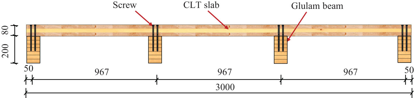
Cross-section of the prefabricated glulam-CLT composite floor.
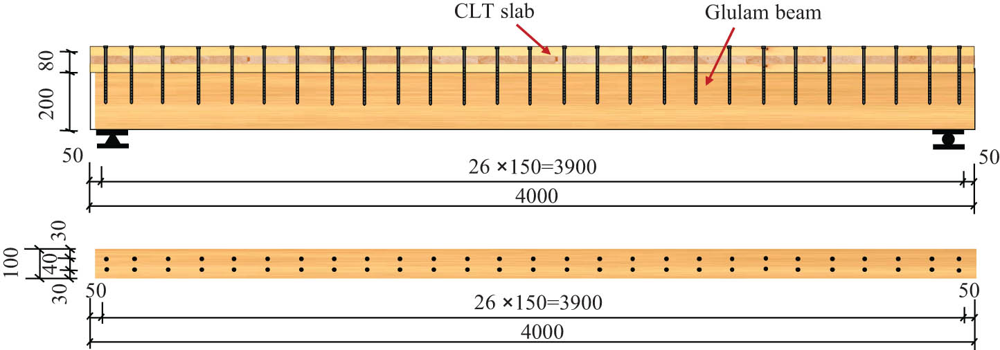
Arrangement of screw connections in the prefabricated composite floor.
The glulam beams were made of larch lumber pieces with an average density of 562 kg·m−3 and a moisture content of 14.4%. To measure the mechanical properties of the timber components, axial compression tests were conducted based on the guidelines of GB/T 15777 [30]. The compressive strength parallel to the grain of the glulam was 53.9 MPa, and the elastic modulus was 12.5 GPa. The CLT member was made of Pinus sylvestris with an average density of 420 kg·m−3 and a moisture content of 9.4%. The compressive strength parallel to the grain of the Pinus sylvestris was 48.1 MPa, and the elastic modulus was 13.2 GPa. The yield strength of the screw connectors used in this test was 370 MPa, and the tensile strength was 463 MPa.
2.2 Test setup and loading process
The composite floor specimen was simply supported at both ends, and an equivalent concentrated load was applied to simulate the uniformly distributed loads on the composite floor, as shown in Figure 3. The loads were applied to the composite floor by using 1,000 kN hydraulic jacks. The specification of pressure load sensor was 1,000 kN, and the output sensitivity was 1.0–1.5 mV·V−1. The loading system followed the multi-stage loading based on the predicted maximum load. First, a preloading stage was conducted to check the working condition of bending test setup and measurement device, which consisted of three levels with each level being 5% of the predicted maximum load. During the formal loading stage, each level of loading was set to 5% of the predicted maximum load with a speed of 0.5 kN·s−1. When the loading reached 90% of the predicted maximum load, the load was further increased using the displacement control method until the composite floor was damaged. The applied load, strain, and deflection data of the composite floor were recorded continuously during the bending test.
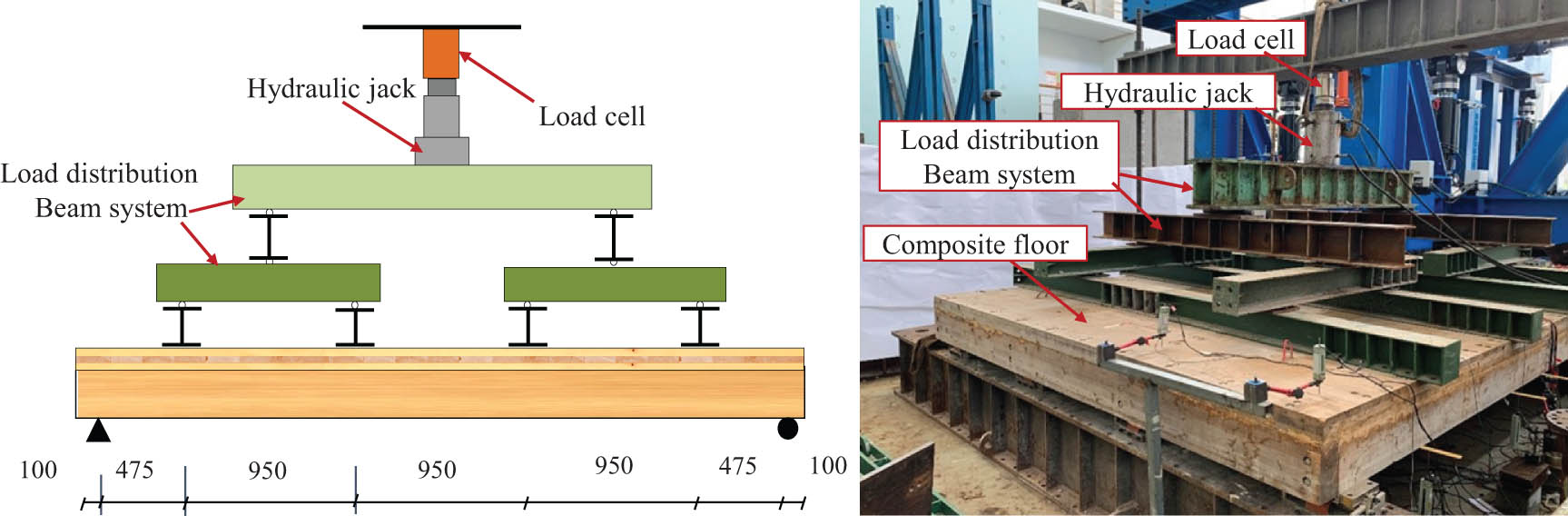
Bending test setup of composite floor.
Figure 4 shows the arrangement of the displacement meters and strain gauges on the glulam-CLT composite floor. The displacement meter range is 0–100 mm, and the output sensitivity is 200 με·mm−1. To accurately measure the deflection of the composite floor and the settlement displacement of the supports, the displacement meters were installed at the mid-span of the floor beams and at the support locations. Displacement meters were also placed along the composite interface to measure the relative slip between the CLT flanges and the glulam beams. Strain gauges were installed along the longitudinal direction of the composite floor at the top of the flanges to measure the longitudinal strains of the CLT flange under the bending loadings. Additionally, strain gauges were placed along the transverse direction at the top of the CLT flange to determine the effective width of the CLT flange. Strain gauges were evenly distributed along the height direction at the mid-span of the glulam beams and the CLT flange to measure the strain variations and validate the plane section assumption.
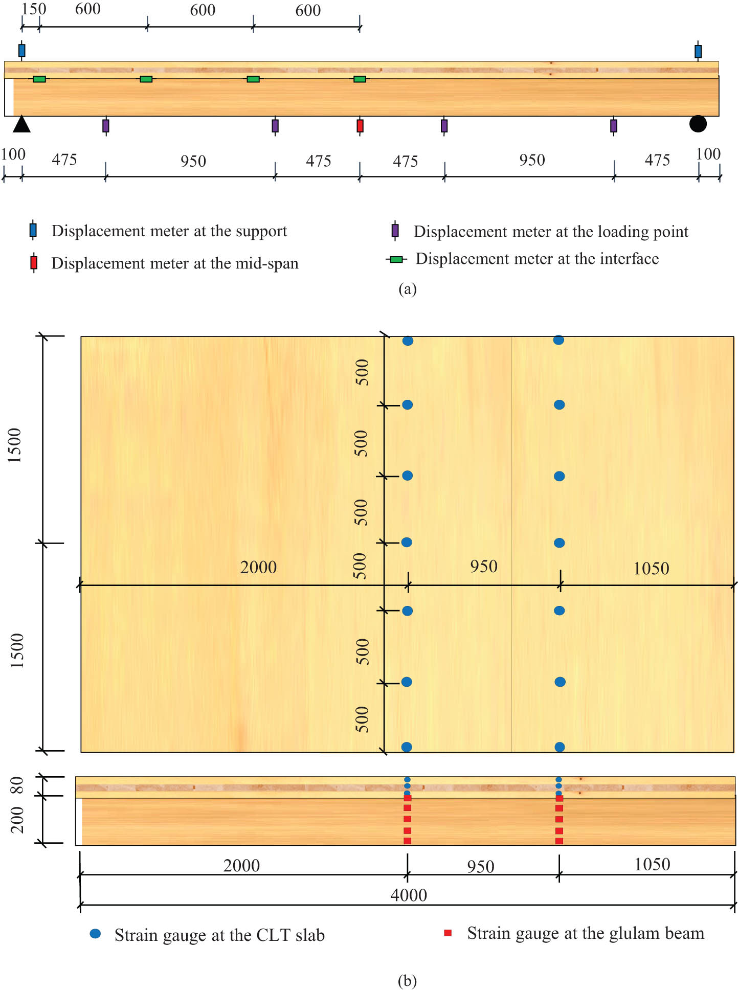
Arrangement of measuring points. (a) Arrangement of displacement meters. (b) Arrangement of strain gauges.
3 Bending test results
3.1 Test phenomenon and failure mechanism
During the initial stages of loading, the glulam beams and CLT flange exhibited minimal relative slip and uplift displacement, indicating overall structural performance of the composite floor. This initial phase demonstrated the integrity and synergy between the glulam and CLT components under lighter loads. However, as the load increased, several types of cracks and damage began to manifest. At a load of 179 kN, significant transverse cracks were observed at the edge beams, which continued to propagate as loading persisted (Figure 5(a)). These transverse cracks indicated stress concentrations and weaknesses in the edge regions of the beams. When the load reached 223 kN, a noticeable bending deformation was observed in the composite floor, suggesting that the structure was beginning to experience more substantial stress and strain. At this point, slight vertical and horizontal cracks appeared on the side of the CLT flange (Figure 5(b)), signaling the initiation of damage within the flange material. As the load continued to increase, the cracks in the CLT flange became more pronounced and spread further, showing the progressive nature of the damage under increasing stress. At a load of 399 kN, a distinct tearing sound was heard, indicative of significant internal damage to the glulam beam. Finally, at a load of 469 kN, the glulam-CLT composite floor experienced brittle failure, a sudden and complete loss of structural integrity. After unloading, a detailed examination of the entire floor revealed that the glulam beams exhibited tensile failure, characterized by significant splitting at the bottom of the glulam members (Figure 5(c)). Additionally, cracks were observed along the longitudinal direction on the CLT flange near the loading points, as well as cracks along the width direction of the CLT flange in the middle portion (Figure 5(d)). These observations underscore the areas of the composite floor that were most vulnerable under the applied loads, providing valuable insights into the structural behavior and failure mechanisms of the glulam-CLT composite floor system.
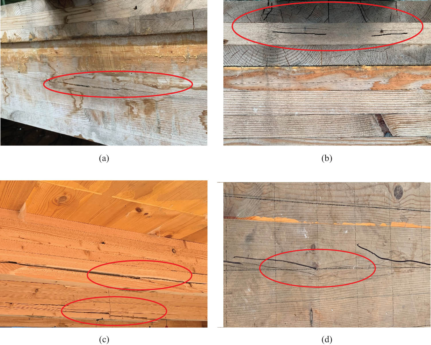
Test phenomenon and failure mode of composite floor. (a) Cracks at the edge of glulam beam. (b) Cracks at the side of CLT flange. (c) Tensile fracture of glulam beam. (d) Longitudinal crack at the top of CLT flange.
3.2 Load–deflection behavior
Figure 6 illustrates the relationship between applied loads and mid-span deflections of the glulam-CLT composite floor. During the initial loading phase, the composite floor exhibited a linear deflection response, proportional to the applied load. This linear behavior indicated that the structure maintained the flexural rigidity and stiffness under lower loads, demonstrating the initial integrity of the composite system. However, as the load approached approximately 85% of the maximum load capacity, the deflection curves began to exhibit a nonlinear increase. This nonlinear response indicated a significant reduction in the flexural rigidity of the glulam-CLT composite floor. The observed reduction in bending stiffness was primarily attributed to the substantial bending deformations experienced by the screw connections under increasing shear forces. These bending deformations compromised the shear stiffness of the screw connections, resulting in a decrease in the overall composite action between the glulam beams and the CLT flange. During the early stages of loading, the deflection deformations of both the middle beams and edge beams in the composite floor were similar. However, as the load increased, the deflection deformation of the mid-span beam began to exceed that of the edge beams. At the ultimate load limit, the mid-span beam deflection reached 63.6 mm, while the edge beams exhibited a deflection of 55.6 mm. This represented a 14.4% increase in deflection deformation for the mid-span beam compared to the edge beams. This could be attributed to the fact that the middle beams bore a greater load compared to the edge beams. These observations highlight the critical behavior of the glulam-CLT composite floor under loading conditions, emphasizing the importance of understanding the distribution of loads and the corresponding deflection responses to ensure structural integrity and performance.
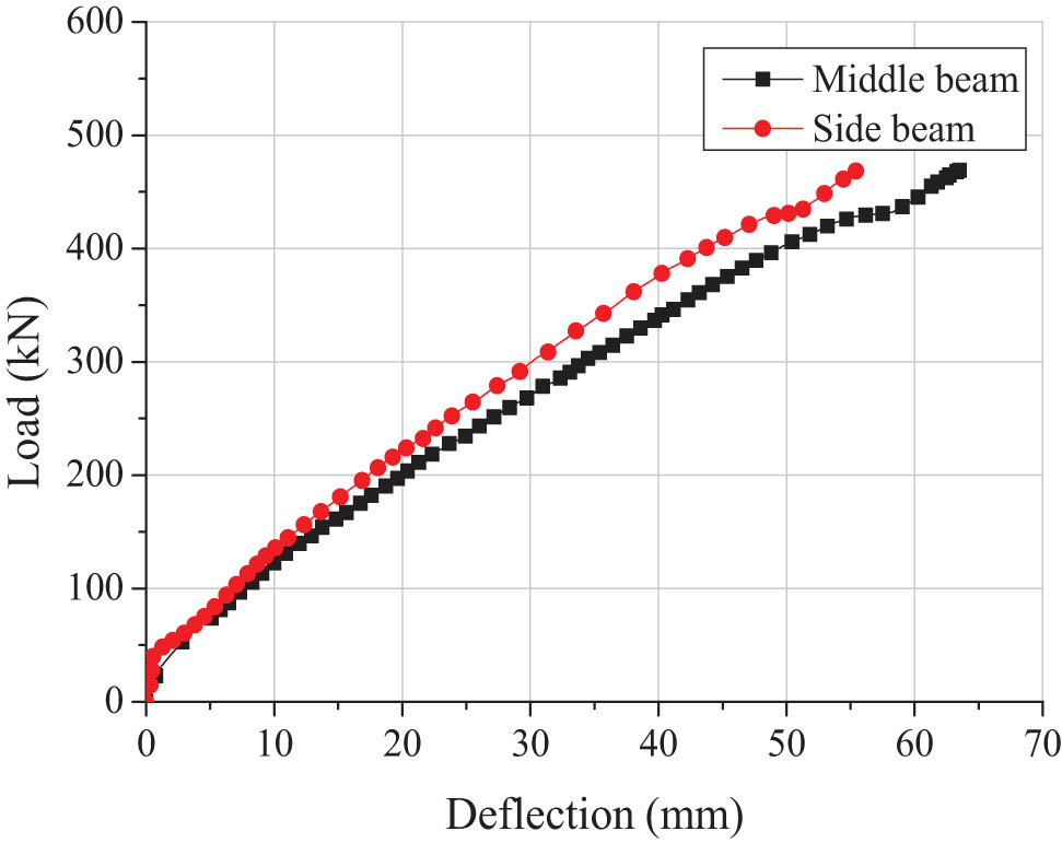
Load-deflection curves of composite floor.
3.3 Interface slip
The composite floor system consisted of the CLT flange and glulam beams, which were connected by flexible screw connections. These screws, designed as flexible shear connectors, experienced significant deformations when subjected to horizontal shear forces. The bending deformations of the screw connections led to the relative slip at the interface of the composite beam. Additionally, the wood materials were prone to deformation under compression, further contributing to increased relative slip at the interface. The slip curves at the interface between the CLT flange and glulam beams are shown in Figure 7, where s is the relative slip and x is the distance from the section to the mid-span. In the initial loading stage, the relationship between the applied load and relative slips was linear, indicating uniform initial stress distribution and good composite action. As the load increased, the relative slips extended toward the mid-span, and the rate of increase in relative slip gradually accelerated. This behavior could be attributed to the decreasing shear rigidity of the screw fasteners and the overall reduction in composite action. The interface slips of the middle beam were observed to be greater than those of the side beams, which was indicative of the larger proportion of the applied load borne by the middle beam compared to the side beams. As the applied loads increased, the relative slips increased. The observed behavior emphasized the importance of considering the flexibility and shear rigidity of the screw connections in the design and analysis of composite floor systems to ensure adequate load transfer and structural integrity. Overall, the increase in applied loads led to greater relative slips, which in turn signaled a decrease in the efficiency of the composite action.
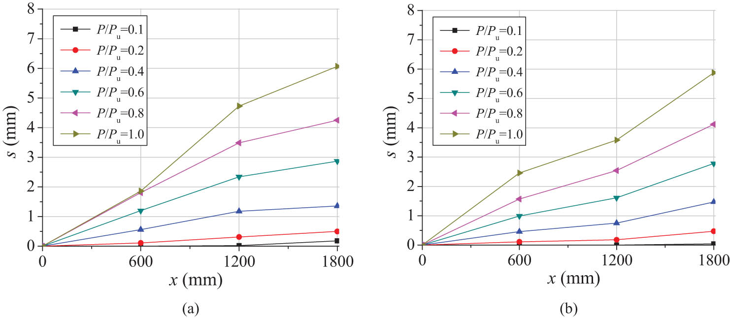
Load–slip curves of composite floor. (a) Middle beam and (b) edge beam.
3.4 Strain distribution of composite floor
Figure 8 presents the strain distributions at the mid-span section of the glulam-CLT composite floor, where ε is the strain and h is the section height. The strain distribution along the height direction of the mid-span section of the floor beam was essentially linear, indicating a linear strain profile. The strain distribution of the composite section satisfied the plane section assumption. However, as the load increased, the relative slips occurred between the glulam beams and the CLT flange, which caused the strain distribution of the composite section to deviate from the assumption of a plane section. Nevertheless, the strain distribution of the CLT flange and the glulam beam individually still satisfied the assumption of a plane section. With the increase in load, the neutral axis of the glulam beam showed a downward shift toward the center of the beam, whereas the neutral axis of the CLT flange displayed an upward movement toward the center of the flange. Consequently, these changes in neutral axis positions resulted in a discontinuous and less uniform strain distribution within the composite section. As the load further increased, the discontinuity in the strain distribution became more pronounced. Overall, the plane section assumption of the composite section was initially satisfied but became invalid as the load increased, resulting in notable changes in the strain distribution and the positions of the neutral axis of the glulam members and CLT flange.
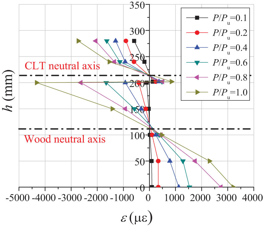
Strain distribution at the mid-span section of composite floor.
The longitudinal strain distribution of the CLT flange along the width direction of the composite floor is shown in Figure 9, where ε is the strain and x c is the distance from the section to the flange center. In the early loading stage, the longitudinal strain of the CLT flange showed a uniform distribution along the width direction, indicating relatively uniform stress in the flange. However, as the load increased, the longitudinal strain of the CLT flange increased dramatically due to the development of wood cracks. The growth of compressive stress in the entire compression flange of the composite floor was not synchronous, and the compressive stresses in the flange sides were smaller than the compressive stress in the upper compression zone of the glulam beam. The longitudinal strain distribution of the CLT flange exhibited a curved pattern along the width direction. This behavior was attributed to the shear deformations and the shear lag effects within the CLT flange. These effects resulted in higher strain values at the mid-span of the CLT flange compared to the quarter-span of the flange. Overall, the strain distribution was initially uniform, but it became curved along the width direction with the increase in the load. These findings provided valuable insights into the behavior of the CLT flange under load and emphasized the non-uniform stress distribution caused by shear lag effects.
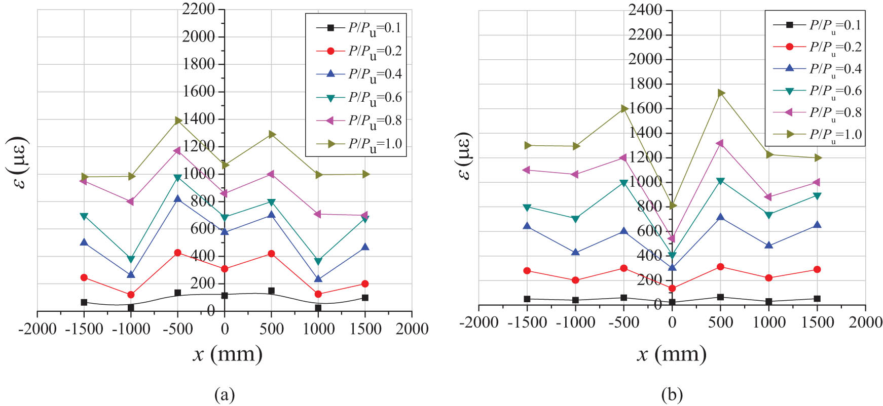
Longitudinal strain distribution of the CLT flange. (a) Mid-span and (b) quarter-span.
4 Theoretical methods for flexural performance of composite floor
4.1 Bending stiffness of composite floor
The test results showed that the growth of compressive stress in the entire compression flange of the composite floor was not synchronous, and the compressive stresses in the flange section on both sides were smaller than the compressive stress in the upper compression zone of the glulam beam. The longitudinal strain distribution of the CLT flange exhibited a curved pattern along the width direction due to the shear deformations and the shear lag effects within the CLT flange. To account for the impact of uneven distribution of the compressive stresses on the CLT flange, the effective width of the CLT flange b eff was adopted. It was assumed that the compressive stresses were uniformly distributed within the effective width range, while the compressive stress outside this range was not considered. The effective flange width in T-section bending members can be determined by the simplified calculation method [31].
where b 2 = beam width; l = beam span; and s n = clear distance between the rib beams.
In order to consider the impact of joint work between the glulam beams and CLT flange on the mechanical performance of the floor beams, the floor beams in the glulam-CLT composite floor can be calculated and analyzed according to a T-shaped section beam. The complex M-shaped section of the composite floor was simplified as a T-section composite beam. The glulam-CLT composite floor with flexible connectors was treated as a partially connected composite structural system. The interface slips between the glulam beam and CLT flange significantly affected the flexural rigidity of the composite floor. Currently, the linear-elastic calculation method is widely used in designing the composite beams with flexible connectors. It was assumed that the mechanical properties of the CLT flange, glulam members, and shear connectors remained within the linear-elastic range until the glulam beam was damaged. Eurocode 5 [32] presented a simplified calculation method to predict the flexural rigidity of the composite beam with a partial shear connection. This method considered the effects of interface slip and the linear-elastic behavior of the materials to estimate the flexural rigidity of the glulam-CLT composite floor (Figure 10).
where EI eff is the flexural rigidity of composite beam; E 1 is the elastic modulus of the CLT flange; E 2 is the elastic modulus of the glulam beam; I 1 is the inertia moment of the CLT flange; I 2 is the inertia moment of the glulam beam; A 1 is the cross-sectional area of the CLT flange; A 2 is the cross-sectional area of the glulam beam; K s is the shear stiffness of shear connections; s is the spacing of shear connections; l is the beam length; γ 1 is the connection efficiency factor for the CLT flange; and γ 2 is the connection efficiency factor for the timber beam, γ 2 = 1.
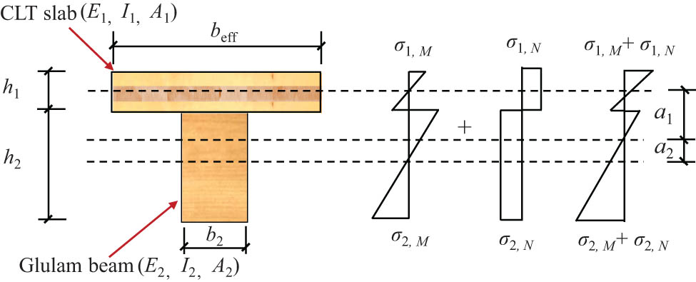
Sectional stress analysis of the glulam-CLT composite floor.
Table 1 illustrates the comparison between the experimental results and theoretical results of the mid-span deflection of the composite floors, where Δ t is the experimental result of mid-span deflection under the serviceability limit state, Δ t = l/250; Δ c is the theoretical result of mid-span deflection. The average value of Δ t/Δ c for the calculation method is 1.01, with a coefficient of variation of 9.4%. It was observed that the analytical approach used for determining the flexural rigidity of the glulam-CLT composite floors was valid and provided accurate estimations. Additionally, the calculation model for the bending stiffness of glulam-CLT composite floor took into account various factors such as material properties, cross-sectional dimensions of components and shear performance of shear connections. This method could provide a certain theoretical foundation for the design of glulam-CLT composite floor.
Comparison between the experimental results and calculated results of the mid-span deflection
| Ref. | Specimens | Test Δ t (mm) | Theoretical Δ c (mm) | Δ t/Δ c |
|---|---|---|---|---|
| This study | GCF-1 | 15.0 | 12.6 | 1.19 |
| [29] | C1 | 25.6 | 27.0 | 0.95 |
| C2 | 25.6 | 24.8 | 1.03 | |
| D1 | 25.6 | 25.4 | 1.01 | |
| D2 | 25.6 | 22.8 | 1.12 | |
| E1 | 25.6 | 25.2 | 1.02 | |
| E2 | 25.6 | 24.5 | 1.05 | |
| F1 | 25.6 | 27.3 | 0.94 | |
| F2 | 25.6 | 23.7 | 1.08 | |
| [33] | B#1 | 15.0 | 14.6 | 0.89 |
| B#2 | 15.0 | 14.8 | 1.00 | |
| B#3 | 15.0 | 14.6 | 0.82 | |
| B#4 | 15.0 | 15.1 | 1.07 | |
| Mean value | 1.01 | |||
| Coefficient of variation (%) | 9.4 | |||
4.2 Flexural bearing capacity of composite floor
The linear-elastic calculation method has been extensively employed for determining the ultimate bearing capacity of the wood beams. It was assumed that mechanical properties of the CLT flange, wood members, and shear connectors remained within the linear-elastic range until the glulam beam was damaged. Accordingly, the flexural capacity of the composite beam is predicted based on the ultimate limit state of wood beam, CLT flange, and shear connection. Once the bending stiffness of the glulam-CLT composite floor is determined, the normal stress of the wood beam and CLT flange can be calculated as follows:
where σ1,M (x) is the flexural stress of the CLT flange; σ2,M (x) is the flexural stress of the glulam beam; σ1,N (x) is the axial stress of the CLT flange; σ2,N (x) is the axial stress of the glulam beam; h 1 is the height of the CLT flange; and h 2 is the height of the glulam beam.
The ultimate limit state of the CLT flange under combined bending and compressive stress can be determined by
The ultimate limit state of wood beam under combined bending and tensile stress can be determined by
The ultimate limit state of shear connection is determined as follows:
where f c is the compressive strength of CLT; f m is the bending strength of glulam; f t is the tensile strength of glulam; and T R is the load carrying capacity of shear connection.
Table 2 illustrates the comparisons between the experimental results and theoretical results of the ultimate bearing capacity of the glulam-CLT composite floors, where F u,t is the experimental result of ultimate bearing capacity; F u,c is the theoretical result of ultimate bearing capacity. The comparison results showed that the mean ratio between the experimental results and theoretical results was 1.02, and the coefficient of variation was 12.8%. It indicated that the analytical approach used for determining the ultimate bearing capacity of the glulam-CLT composite floors was proved to be accurate and reliable. In addition, the calculation method for the bending bearing capacity of glulam-CLT composite floor took into account various factors such as material properties, cross-sectional dimensions of components and shear performance of shear connections. This method could provide a certain theoretical foundation for the design of glulam-CLT composite floor.
Comparison between the experimental and theoretical results of flexural bearing capacity
| Ref. | Specimens | Test M u,t (kN·m) | Theoretical M u,c (kN·m) | M u,t/M u,c |
|---|---|---|---|---|
| This study | GCF-1 | 26.8 | 31.0 | 0.86 |
| [29] | C1 | 28.80 | 25.9 | 1.11 |
| C2 | 23.68 | 20.4 | 1.16 | |
| D1 | 40.00 | 36.4 | 1.10 | |
| D2 | 33.92 | 35.4 | 0.96 | |
| E1 | 18.53 | 20.6 | 0.90 | |
| E2 | 17.06 | 20.2 | 0.85 | |
| F1 | 21.60 | 20.9 | 1.04 | |
| F2 | 17.60 | 20.6 | 0.86 | |
| [33] | B#1 | 26.3 | 20.1 | 1.30 |
| B#2 | 25.6 | 23.3 | 1.10 | |
| B#3 | 24.3 | 24.0 | 1.01 | |
| B#4 | 26.6 | 27.4 | 0.97 | |
| Mean value | 1.02 | |||
| Coefficient of variation (%) | 12.8 | |||
5 Conclusion
Based on the bending test of the glulam-CLT composite floor with screw connections, the study comprehensively analyzed the failure mechanism, load-deflection behavior, interface slip and strain distribution of the glulam-CLT composite floor. The test results of the composite floor indicated that the failure mode was tensile fracture of the glulam beams at the bottom. The cracks along the longitudinal direction occurred on the CLT flange near the loading points, as well as the cracks along the width direction of the CLT flange in the middle portion. At the early loading stage, the relative slips first appeared at the end interface of the composite beams. As the load increased, the relative slips extended toward the mid-span, and the rate of increase in relative slip gradually increased.
During the early stage of loading, the glulam-CLT composite floor exhibited linear deflection deformation with the increase in the applied loads. When the load reached about 85% of the maximum load, the deflection curve exhibited a nonlinear increase with further applied load. It indicated a reduction in the flexural rigidity of the glulam-CLT composite floor. This behavior could be attributed to a decrease in the shear stiffness of screw connections and an overall decline in composite action between the glulam members and the CLT flange. In addition, as the load increased, the deflection deformation of the mid-span beam exceeded that of the edge beam. When the load reached its ultimate limit, the deflection deformation of the mid-span beam increased by 14.4% compared to the edge beam.
The plane section assumption of the composite section was initially satisfied but became invalid as the load increased, resulting in notable changes in the strain distribution and the positions of the neutral axis of the glulam members and CLT flange. As the load increased, the longitudinal strain of the CLT flange increased dramatically due to the development of wood cracks. The longitudinal strain distribution of the CLT flange exhibited a curved pattern along the width direction. This behavior was attributed to the shear deformations and the shear lag effects within the CLT flange.
Furthermore, the M-shaped section of the glulam-CLT composite floor was simplified as T-section composite beams to calculate the bending performance of the composite floor. The linear-elastic method for determining the flexural rigidity and ultimate bearing capacity of the glulam-CLT composite floors was proved to be accurate and reliable.
The finite element analysis on the glulam-CLT composite floor will be conducted to study the influences of the shear connection ratio, shear connection type, width, and thickness of CLT flange. Push-out tests will be performed to investigate the mechanical performance of shear connectors in the glulam-CLT composite floor. The effects of dowel diameter, embedding length of dowel and shear connection type on the shear behavior will be studied.
Acknowledgments
The authors appreciate the support from the Laboratory of Structural and Bridge Engineering, Nanjing Tech University.
-
Funding information: The research was supported by National Natural Science Foundation of China (No. 52208257), Natural Science Foundation of Colleges and Universities of Jiangsu Province (22KJB560023), and China Postdoctoral Science Foundation (2023M731711).
-
Author contributions: Hao Du: writing – original draft, project administration, methodology, investigation, funding acquisition, and validation. Gang Chen: validation, investigation, and data curation. Weijie Fu: data curation and validation. Xiamin Hu: Writing – review and editing and supervision. All authors have accepted responsibility for the entire content of this manuscript and approved its submission.
-
Conflict of interest: The authors state no conflict of interest.
-
Data availability statement: The datasets generated during and/or analyzed during the current study are available from the corresponding author upon reasonable request.
References
[1] Himes, A. and G. Busby. Wood buildings as a climate solution. Developments in the Built Environment, Vol. 4, 2020, id. 100030.10.1016/j.dibe.2020.100030Search in Google Scholar
[2] Li, H., Y. Wei, L. Yan, E. S. Katherine, and C. Dai. In-plane compressive behavior of short cross-laminated bamboo and timber. Industrial Crops & Products, Vol. 200, 2023, id. 116807.10.1016/j.indcrop.2023.116807Search in Google Scholar
[3] Pastori, S., E. Sergio Mazzucchelli, and M. Wallhagen. Hybrid timber-based structures: A state of the art review. Construction and Building Materials, Vol. 359, 2022, id. 129505.10.1016/j.conbuildmat.2022.129505Search in Google Scholar
[4] Ayanleye, S., K. Udele, V. Nasir, X. Zhang, and H. Militz. Durability and protection of mass timber structures: A review. Journal of Building Engineering, Vol. 46, 2022, id. 103731.10.1016/j.jobe.2021.103731Search in Google Scholar
[5] Zhao, K., Y. Wei, S. Chen, Y. Lin, and L. Huang. Bending properties and design strength of reconstituted bamboo at different temperatures. Polymer Composites, Vol. 44, No. 3, 2023, pp. 1822–1835.10.1002/pc.27207Search in Google Scholar
[6] Chen, F., M. Li, and Z. Li. Self-centering mass timber structures: A review on recent research progress. Engineering Structures, Vol. 303, 2024, id. 117474.10.1016/j.engstruct.2024.117474Search in Google Scholar
[7] Uwizeyimana, P., M. Perrin, and F. Eyma. Moisture monitoring in glulam timber structures with embedded resistive sensors: study of influence parameters. Wood Science and Technology, Vol. 54, No. 6, 2020, pp. 1463–1478.10.1007/s00226-020-01228-8Search in Google Scholar
[8] Sun, X., M. He, and Z. Li. Novel engineered wood and bamboo composites for structural applications: State-of-art of manufacturing technology and mechanical performance evaluation. Construction and Building Materials, Vol. 249, 2020, id. 118751.10.1016/j.conbuildmat.2020.118751Search in Google Scholar
[9] Du, H., X. Hu, Z. Xie, and Y. Meng. Experimental and analytical investigation on fire resistance of glulam-concrete composite beams. Journal of Building Engineering, Vol. 44, 2021, id. 103244.10.1016/j.jobe.2021.103244Search in Google Scholar
[10] Brandner, R., G. Flatscher, A. Ringhofer, G. Schickhofer, and A. Thiel. Cross laminated timber (CLT): overview and development. European Journal of Wood and Wood Products, Vol. 74, No. 3, 2016, pp. 331–351.10.1007/s00107-015-0999-5Search in Google Scholar
[11] Brown, J. R., M. Li, T. Tannert, and D. Moroder. Experimental study on orthogonal joints in cross-laminated timber with self-tapping screws installed with mixed angles. Engineering Structures, Vol. 228, 2021, id. 111560.10.1016/j.engstruct.2020.111560Search in Google Scholar
[12] Flatscher, G. and G. Schickhofer. Shaking-table test of a cross-laminated timber structure. Structures and Buildings, Vol. 168, No. 11, 2015, pp. 878–888.10.1680/stbu.13.00086Search in Google Scholar
[13] Li, H., Y. Wei, L. Yan, E. S. Katherine, and C. Dai. Structural behavior of steel dowel strengthened cross-laminated bamboo and timber beams. Composite Structures, Vol. 318, 2023, id. 117111.10.1016/j.compstruct.2023.117111Search in Google Scholar
[14] Stürzenbecher, R., K. Hofstetter, and J. Eberhardsteiner. Structural design of cross laminated timber (CLT) by advanced plate theories. Composites Science and Technology, Vol. 70, No. 9, 2010, pp. 1368–1379.10.1016/j.compscitech.2010.04.016Search in Google Scholar
[15] Du, H., J. Mei, W. Fu, and X. Hu. Experimental research on bending performance of wood-concrete composite slab with screw connections. Bioresources, Vol. 19, No. 1, 2024, pp. 1558–1570.10.15376/biores.19.1.1558-1570Search in Google Scholar
[16] Filiatrault, A., D. Fischer, B. Folz, and C. M. Uang. Experimental parametric study on the in-plane stiffness of wood diaphragms. Canadian Journal of Civil Engineering, Vol. 29, No. 4, 2002, pp. 554–566.10.1139/l02-036Search in Google Scholar
[17] James, W. B. Horizontal stiffness of wood diaphragms, Virginia Polytechnic Institute and State University, Blacksburg, 2005.Search in Google Scholar
[18] Baldessari, C. In-plane behaviour of differently refurbished timber floors, University of Trento, Trento, 2010.Search in Google Scholar
[19] Aicher, S. and C. Stritzke. Novel lightweight timber composite element: web design in shear and compression. Materials and Joints in Timber Structures, Vol. 9, 2014, pp. 135–148.10.1007/978-94-007-7811-5_13Search in Google Scholar
[20] Gavric, I., M. Fragiacomo, and A. Ceccotti. Cyclic behavior of CLT wall systems: experimental tests and analytical prediction models. Journal of Structural Engineering, Vol. 141, No. 11, 2015, id. 04015034.10.1061/(ASCE)ST.1943-541X.0001246Search in Google Scholar
[21] Izzi, M., D. Casagrande, S. Bezzi, D. Pasca, M. Follesa, and R. Tomasi. Seismic behaviour of cross-laminated timber structures: A state-of-the-art review. Engineering Structures, Vol. 170, 2018, pp. 42–52.10.1016/j.engstruct.2018.05.060Search in Google Scholar
[22] Blass, H. J. and P. Fellmoser. Design of solid wood panels with cross layers. WCTE 2004-World Conference on Timber Engineering, Lahti, Finland, 2004.Search in Google Scholar
[23] Bejtka, I. and F. Lam. Cross laminated timber as innovative building material. Proceedings of the Canadian Society for Civil Engineering (CSCE) annual conference, Quebec City, Canada, 2008.Search in Google Scholar
[24] Wang, Z., M. Gong, and Y. Chui. Mechanical properties of laminated strand lumber and hybrid cross-laminated timber. Construction and Building Materials, Vol. 101, 2015, pp. 622–627.10.1016/j.conbuildmat.2015.10.035Search in Google Scholar
[25] He, M., X. Sun, and Z. Li. Bending and compressive properties of cross-laminated timber (CLT) panels made from Canadian hemlock. Construction and Building Materials, Vol. 185, 2018, pp. 175–183.10.1016/j.conbuildmat.2018.07.072Search in Google Scholar
[26] Vessby, J., B. Enquist, H. Petersson, and T. Alsmarker. Experimental study of cross-laminated timber wall panels. European Journal of Wood and Wood Products, Vol. 67, No. 2, 2009, pp. 211–218.10.1007/s00107-009-0313-5Search in Google Scholar
[27] Ringhofer, A., R. Brandner, and H. J. Blaß. Cross laminated timber (CLT): Design approaches for dowel-type fasteners and connections. Engineering Structures, Vol. 171, 2018, pp. 849–861.10.1016/j.engstruct.2018.05.032Search in Google Scholar
[28] Zhang, C., R. Harris, and W. Chang. Strain distribution of dowel-type connections reinforced with self-tapping screws. Journal of Materials in Civil Engineering, Vol. 32, No. 1, 2020, id. 04019319.10.1061/(ASCE)MT.1943-5533.0002883Search in Google Scholar
[29] Giongo, I., G. Schiro, K. Walsh, and D. Riccadonna. Experimental testing of pre-stressed timber-to-timber composite (TTC) floors. Engineering Structures, Vol. 201, 2019, id. 109808.10.1016/j.engstruct.2019.109808Search in Google Scholar
[30] GB/T 15777. Method for determination of the modulus of elasticity in compression parallel to grain of wood, Standards Press of China, China, 2017.Search in Google Scholar
[31] EN 1994-1-1: 2004. Eurocode 4: design of composite steel and concrete structures Part 1-1: General rules and rules for buildings, European Committee for Standardization, Brussels, Belgium, 2004.Search in Google Scholar
[32] EN 1995-1-1. Eurocode 5: Design of timber structures-Part 1-1: General rules and rules for buildings, European Committee for Standardization, Brussels, Belgium, 2004.Search in Google Scholar
[33] Bedon, C. and M. Fragiacomo. Numerical analysis of timber-to-timber joints and composite beams with inclined self-tapping screws. Composite Structures, Vol. 207, 2019, pp. 13–28.10.1016/j.compstruct.2018.09.008Search in Google Scholar
© 2024 the author(s), published by De Gruyter
This work is licensed under the Creative Commons Attribution 4.0 International License.
Articles in the same Issue
- Review Articles
- Effect of superplasticizer in geopolymer and alkali-activated cement mortar/concrete: A review
- Experimenting the influence of corncob ash on the mechanical strength of slag-based geopolymer concrete
- Powder metallurgy processing of high entropy alloys: Bibliometric analysis and systematic review
- Exploring the potential of agricultural waste as an additive in ultra-high-performance concrete for sustainable construction: A comprehensive review
- A review on partial substitution of nanosilica in concrete
- Foam concrete for lightweight construction applications: A comprehensive review of the research development and material characteristics
- Modification of PEEK for implants: Strategies to improve mechanical, antibacterial, and osteogenic properties
- Interfacing the IoT in composite manufacturing: An overview
- Advances in processing and ablation properties of carbon fiber reinforced ultra-high temperature ceramic composites
- Advancing auxetic materials: Emerging development and innovative applications
- Revolutionizing energy harvesting: A comprehensive review of thermoelectric devices
- Exploring polyetheretherketone in dental implants and abutments: A focus on biomechanics and finite element methods
- Smart technologies and textiles and their potential use and application in the care and support of elderly individuals: A systematic review
- Reinforcement mechanisms and current research status of silicon carbide whisker-reinforced composites: A comprehensive review
- Innovative eco-friendly bio-composites: A comprehensive review of the fabrication, characterization, and applications
- Review on geopolymer concrete incorporating Alccofine-1203
- Advancements in surface treatments for aluminum alloys in sports equipment
- Ionic liquid-modified carbon-based fillers and their polymer composites – A Raman spectroscopy analysis
- Emerging boron nitride nanosheets: A review on synthesis, corrosion resistance coatings, and their impacts on the environment and health
- Mechanism, models, and influence of heterogeneous factors of the microarc oxidation process: A comprehensive review
- Synthesizing sustainable construction paradigms: A comprehensive review and bibliometric analysis of granite waste powder utilization and moisture correction in concrete
- 10.1515/rams-2025-0086
- Research Articles
- Coverage and reliability improvement of copper metallization layer in through hole at BGA area during load board manufacture
- Study on dynamic response of cushion layer-reinforced concrete slab under rockfall impact based on smoothed particle hydrodynamics and finite-element method coupling
- Study on the mechanical properties and microstructure of recycled brick aggregate concrete with waste fiber
- Multiscale characterization of the UV aging resistance and mechanism of light stabilizer-modified asphalt
- Characterization of sandwich materials – Nomex-Aramid carbon fiber performances under mechanical loadings: Nonlinear FE and convergence studies
- Effect of grain boundary segregation and oxygen vacancy annihilation on aging resistance of cobalt oxide-doped 3Y-TZP ceramics for biomedical applications
- Mechanical damage mechanism investigation on CFRP strengthened recycled red brick concrete
- Finite element analysis of deterioration of axial compression behavior of corroded steel-reinforced concrete middle-length columns
- Grinding force model for ultrasonic assisted grinding of γ-TiAl intermetallic compounds and experimental validation
- Enhancement of hardness and wear strength of pure Cu and Cu–TiO2 composites via a friction stir process while maintaining electrical resistivity
- Effect of sand–precursor ratio on mechanical properties and durability of geopolymer mortar with manufactured sand
- Research on the strength prediction for pervious concrete based on design porosity and water-to-cement ratio
- Development of a new damping ratio prediction model for recycled aggregate concrete: Incorporating modified admixtures and carbonation effects
- Exploring the viability of AI-aided genetic algorithms in estimating the crack repair rate of self-healing concrete
- Modification of methacrylate bone cement with eugenol – A new material with antibacterial properties
- Numerical investigations on constitutive model parameters of HRB400 and HTRB600 steel bars based on tensile and fatigue tests
- Research progress on Fe3+-activated near-infrared phosphor
- Discrete element simulation study on effects of grain preferred orientation on micro-cracking and macro-mechanical behavior of crystalline rocks
- Ultrasonic resonance evaluation method for deep interfacial debonding defects of multilayer adhesive bonded materials
- Effect of impurity components in titanium gypsum on the setting time and mechanical properties of gypsum-slag cementitious materials
- Bending energy absorption performance of composite fender piles with different winding angles
- Theoretical study of the effect of orientations and fibre volume on the thermal insulation capability of reinforced polymer composites
- Synthesis and characterization of a novel ternary magnetic composite for the enhanced adsorption capacity to remove organic dyes
- Couple effects of multi-impact damage and CAI capability on NCF composites
- Mechanical testing and engineering applicability analysis of SAP concrete used in buffer layer design for tunnels in active fault zones
- Investigating the rheological characteristics of alkali-activated concrete using contemporary artificial intelligence approaches
- Integrating micro- and nanowaste glass with waste foundry sand in ultra-high-performance concrete to enhance material performance and sustainability
- Effect of water immersion on shear strength of epoxy adhesive filled with graphene nanoplatelets
- Impact of carbon content on the phase structure and mechanical properties of TiBCN coatings via direct current magnetron sputtering
- Investigating the anti-aging properties of asphalt modified with polyphosphoric acid and tire pyrolysis oil
- Biomedical and therapeutic potential of marine-derived Pseudomonas sp. strain AHG22 exopolysaccharide: A novel bioactive microbial metabolite
- Effect of basalt fiber length on the behavior of natural hydraulic lime-based mortars
- Optimizing the performance of TPCB/SCA composite-modified asphalt using improved response surface methodology
- Compressive strength of waste-derived cementitious composites using machine learning
- Melting phenomenon of thermally stratified MHD Powell–Eyring nanofluid with variable porosity past a stretching Riga plate
- Development and characterization of a coaxial strain-sensing cable integrated steel strand for wide-range stress monitoring
- Compressive and tensile strength estimation of sustainable geopolymer concrete using contemporary boosting ensemble techniques
- Customized 3D printed porous titanium scaffolds with nanotubes loading antibacterial drugs for bone tissue engineering
- Facile design of PTFE-kaolin-based ternary nanocomposite as a hydrophobic and high corrosion-barrier coating
- Effects of C and heat treatment on microstructure, mechanical, and tribo-corrosion properties of VAlTiMoSi high-entropy alloy coating
- Study on the damage mechanism and evolution model of preloaded sandstone subjected to freezing–thawing action based on the NMR technology
- Promoting low carbon construction using alkali-activated materials: A modeling study for strength prediction and feature interaction
- Entropy generation analysis of MHD convection flow of hybrid nanofluid in a wavy enclosure with heat generation and thermal radiation
- Friction stir welding of dissimilar Al–Mg alloys for aerospace applications: Prospects and future potential
- Fe nanoparticle-functionalized ordered mesoporous carbon with tailored mesostructures and their applications in magnetic removal of Ag(i)
- Study on physical and mechanical properties of complex-phase conductive fiber cementitious materials
- Evaluating the strength loss and the effectiveness of glass and eggshell powder for cement mortar under acidic conditions
- Effect of fly ash on properties and hydration of calcium sulphoaluminate cement-based materials with high water content
- Analyzing the efficacy of waste marble and glass powder for the compressive strength of self-compacting concrete using machine learning strategies
- Experimental study on municipal solid waste incineration ash micro-powder as concrete admixture
- Parameter optimization for ultrasonic-assisted grinding of γ-TiAl intermetallics: A gray relational analysis approach with surface integrity evaluation
- Producing sustainable binding materials using marble waste blended with fly ash and rice husk ash for building materials
- Effect of steam curing system on compressive strength of recycled aggregate concrete
- A sawtooth constitutive model describing strain hardening and multiple cracking of ECC under uniaxial tension
- Predicting mechanical properties of sustainable green concrete using novel machine learning: Stacking and gene expression programming
- Toward sustainability: Integrating experimental study and data-driven modeling for eco-friendly paver blocks containing plastic waste
- A numerical analysis of the rotational flow of a hybrid nanofluid past a unidirectional extending surface with velocity and thermal slip conditions
- A magnetohydrodynamic flow of a water-based hybrid nanofluid past a convectively heated rotating disk surface: A passive control of nanoparticles
- Prediction of flexural strength of concrete with eggshell and glass powders: Advanced cutting-edge approach for sustainable materials
- Efficacy of sustainable cementitious materials on concrete porosity for enhancing the durability of building materials
- Phase and microstructural characterization of swat soapstone (Mg3Si4O10(OH)2)
- Effect of waste crab shell powder on matrix asphalt
- Improving effect and mechanism on service performance of asphalt binder modified by PW polymer
- Influence of pH on the synthesis of carbon spheres and the application of carbon sphere-based solid catalysts in esterification
- Experimenting the compressive performance of low-carbon alkali-activated materials using advanced modeling techniques
- Thermogravimetric (TG/DTG) characterization of cold-pressed oil blends and Saccharomyces cerevisiae-based microcapsules obtained with them
- Investigation of temperature effect on thermo-mechanical property of carbon fiber/PEEK composites
- Computational approaches for structural analysis of wood specimens
- Integrated structure–function design of 3D-printed porous polydimethylsiloxane for superhydrophobic engineering
- Exploring the impact of seashell powder and nano-silica on ultra-high-performance self-curing concrete: Insights into mechanical strength, durability, and high-temperature resilience
- Axial compression damage constitutive model and damage characteristics of fly ash/silica fume modified magnesium phosphate cement after being treated at different temperatures
- Integrating testing and modeling methods to examine the feasibility of blended waste materials for the compressive strength of rubberized mortar
- Special Issue on 3D and 4D Printing of Advanced Functional Materials - Part II
- Energy absorption of gradient triply periodic minimal surface structure manufactured by stereolithography
- Marine polymers in tissue bioprinting: Current achievements and challenges
- Quick insight into the dynamic dimensions of 4D printing in polymeric composite mechanics
- Recent advances in 4D printing of hydrogels
- Mechanically sustainable and primary recycled thermo-responsive ABS–PLA polymer composites for 4D printing applications: Fabrication and studies
- Special Issue on Materials and Technologies for Low-carbon Biomass Processing and Upgrading
- Low-carbon embodied alkali-activated materials for sustainable construction: A comparative study of single and ensemble learners
- Study on bending performance of prefabricated glulam-cross laminated timber composite floor
- Special Issue on Recent Advancement in Low-carbon Cement-based Materials - Part I
- Supplementary cementitious materials-based concrete porosity estimation using modeling approaches: A comparative study of GEP and MEP
- Modeling the strength parameters of agro waste-derived geopolymer concrete using advanced machine intelligence techniques
- Promoting the sustainable construction: A scientometric review on the utilization of waste glass in concrete
- Incorporating geranium plant waste into ultra-high performance concrete prepared with crumb rubber as fine aggregate in the presence of polypropylene fibers
- Investigation of nano-basic oxygen furnace slag and nano-banded iron formation on properties of high-performance geopolymer concrete
- Effect of incorporating ultrafine palm oil fuel ash on the resistance to corrosion of steel bars embedded in high-strength green concrete
- Influence of nanomaterials on properties and durability of ultra-high-performance geopolymer concrete
- Influence of palm oil ash and palm oil clinker on the properties of lightweight concrete