Microstructure and mechanical properties of submerged arc welded medium-thickness Q690qE high-strength steel plate joints
-
Wen Huang
 ,
Zhigang Liu
,
Zhigang Liu

Abstract
Submerged arc welding method was used to weld 40 mm thickness Q690qE high-strength steel to study the influence of welding heat input on the microstructure and properties of Q690qE joints. The result shows that welded seam with full penetration and no obvious defects is achieved in the Q690qE joints when the welding heat input ranges from 22.5 to 33.6 kJ·cm−1. The microstructure of welded seam mainly consists of acicular ferrite and granular bainite (GB), the microstructure in coarse-grain zone is GB and lath martensite. As the welding heat input increases, the microstructure of coarse-grain zone becomes lath bainite (LB) and a small amount of GB and the microhardness decreases. The microstructure of the fine-grained area mainly includes ferrite, GB, and a small quantity of LB. In terms of impact toughness, with the heat input increasing, the impact toughness at the center of welded seam and the heat-affected zone decreases subsequently. The tensile test results of the welded joints show that the fracture always occurs in the parent material area, with a tensile strength higher than 864 MPa, and the elongation after fracture decreases as the heat input increases.
1 Introduction
In recent years, with rapid development of bridge construction, toward large span, heavy load, lightweight, longevity, all-welded nodes, high security performance, and other high properties [1–3], the sixth-generation large-span high-strength bridge steel, Q690qE bridge steel, has been applied in more and more actual bridge manufacturing [4,5].
As a new generation of high-strength bridge steel, Q690qE bridge steel is processed using thermomechanical control process and tempering techniques, ultimately achieving a microstructure primarily consisting of bainite and ferrite [6–9]. This results in a yield strength of 690 MPa and a favorable performance match with a yield-to-tensile ratio below 0.85 [10,11]. Some microalloying elements have been added to the steel to improve its microstructural properties, enhance its strength, and provide a certain degree of corrosion resistance. However, the addition of a relatively high amount of alloying elements in Q690qE bridge steel increases its hardening capacity, making welding more challenging [12,13].
Scholars have conducted research on the welding technology of Q690qE steel. Du et al. [14] conducted research on submerged arc welding (SAW) technology for Q690qE, and the study indicates that submerged arc welds possess excellent anti-brittle fracture properties, with both the weld and the heat-affected zone (HAZ) having high crack tip opening displacement characteristics. Wang [15] conducted a study on the strengthening and toughening of the coarse-grained heat-affected zone (CGHAZ) of Q690 bridge steel and found that the microstructure of the CGHAZ mainly consists of lath bainite (LB), granular bainite (GB), and a small amount of martensite. Shin et al. [16] found that the root pass of the welded joints in quenched and tempered high-strength steel exhibited a 17% reduction in impact energy compared to other weld passes. Wang et al. [17] noted the presence of localized brittle zones within the multi-pass weld metal of high-strength steels, whose formation mechanism and microstructural characteristics are very similar to those of CGHAZ in the HAZ. Celin and Burja [18] discovered that the cooling rate has a significant influence on the phase transformation in CGHAZ. When the t 8/5 is less than 20 s, the structure in CGHAZ is martensitic. As the cooling rate decreases, a partial bainitic structure begins to appear, and when the t 8/5 time increases to 80 s, the proportion of bainite significantly increases. Current research on the welding of Q690qE bridge steel primarily concentrates on the description of microstructures and mechanical properties, with a lesser depth of analysis on the relationship between microstructure and mechanical properties.
In this study, under the premise of meeting the production needs of the welded seam, research has been conducted on the relationship between the microstructure and properties of the welded joints in medium-thickness Q690qE bridge steel and the welding heat input. Additionally, the relationship between low-temperature impact performance and microstructure was further explored, aiming to contribute to its application in bridge engineering projects.
2 Materials and methods
The parent material (PM) used in this study is 40 mm Q690qE high-strength steel. Considering the requirements for strength and toughness in the bridge construction, the SAW S80QNH wire and AF85QNH flux are selected. Table 1 shows the chemical composition of Q690qE steel and S80QNH welding wire. The microstructure of the Q690qE high-strength steel PM is shown in Figure 1. It can be seen that the microstructure of Q690qE high-strength steel is mainly composed of LB and ferrite. Q690qE bridge steel has good mechanical properties. The mechanical properties of Q690qE bridge steel and welding wire are shown in Table 2.
Chemical composition of Q690qE steel and S80QNH welding wire
| Material | C | Si | Mn | P | S | Cu | Cr | Ni | Mo | B | V | Nb | Ti |
|---|---|---|---|---|---|---|---|---|---|---|---|---|---|
| Q690qE | 0.061 | 0.14 | 1.41 | 0.005 | 0.001 | 0.25 | 0.45 | 0.55 | 0.24 | 0.005 | 0.007 | 0.035 | 0.009 |
| S80QNH | 0.054 | 0.32 | 1.89 | 0.007 | 0.002 | — | — | 2.70 | — | — | — | — | — |

Microstructure of Q690qE high-strength steel.
Mechanical properties of Q690qE bridge steel and welding wire
| Material | Yield strength of joints (MPa) | Tensile strength of joints (MPa) | Elongation (%) | Impact absorption energy (J (−40°C)) |
|---|---|---|---|---|
| Q690qE | 704 | 801 | 18.0 | 210 |
| S80QNH | 699 | 809 | 16.5 | 136 |
The welding parameters used in this study are shown in Table 3. The groove type and weld bead arrangement are shown in Figure 2. Based on the heat input design for the joints and considering the flatness of the weld surface, the sampling locations in this article are all 1 mm away from the upper surface. The welding heat input are divided into 22.5, 27.9, and 33.6 kJ·cm−1. After welding, metallography and electron back scatter diffraction (EBSD) observations are carried out on the welded joints, using 5% nitric acid alcohol solution for etching. The equipment used for metallographic observation is the Axioskop2-MAT metallographic microscope, and the equipment used for EBSD is the Zeiss Merlin Compact. For the mechanical properties test, the tensile and impact tests were conducted three times for each set of parameters, and the experimental results were averaged. The shape and dimensions of the tensile specimens for the welded joint are shown in Figure 3.
Q690qE SAW process parameters at different heat input
| Process | Welding pass | Welding method | Inter-pass temperature (°C) | Welding current (A) | Welding voltage (V) | Welding speed (cm·min−1) | Welding heat input (kJ·cm−1) |
|---|---|---|---|---|---|---|---|
| Process parameters 1 | 1 | GMAW | 140 | 260 | 28 | 32 | 13.6 |
| 2–12 | SAW | 155–170 | 590 | 30 | 52 | 20.4 | |
| 13–21 | SAW | 160–180 | 630 | 31 | 52 | 22.5 | |
| Process parameters 2 | 1 | GMAW | 140 | 260 | 28 | 32 | 13.6 |
| 2–12 | SAW | 155–170 | 630 | 30 | 45 | 25.2 | |
| 13–21 | SAW | 160–180 | 630 | 31 | 42 | 27.9 | |
| Process parameters 3 | 1 | GMAW | 140 | 260 | 28 | 32 | 13.6 |
| 2–12 | SAW | 155–170 | 650 | 31 | 40 | 30.2 | |
| 13–21 | SAW | 160–180 | 650 | 31 | 36 | 33.6 |

Bevel shape and distribution of welding passes in the welded joint: (a) bevel shape and size, (b) welding passes.

Dimensions of the tensile test specimens for the welded joint.
3 Results and discussion
3.1 Effect of welding heat input on Q690qE joint formation
Figure 4 shows the Q690qE joint cross-section macroscopic morphology at different heat input, in which the white line within the area is the HAZ. The joints are well formed, showing no porosity, cracks, or incomplete welding on the cross-sections. Additionally, the average value of the width in the HAZ of the three welding processes for SAW is 6.82, 6.91, and 7.80 mm, respectively. Accordingly, the width of the HAZ is in a positive correlation with the size of the weld heat input, i.e., the larger the amount of the weld heat input, the wider the width of the HAZ of the joint.
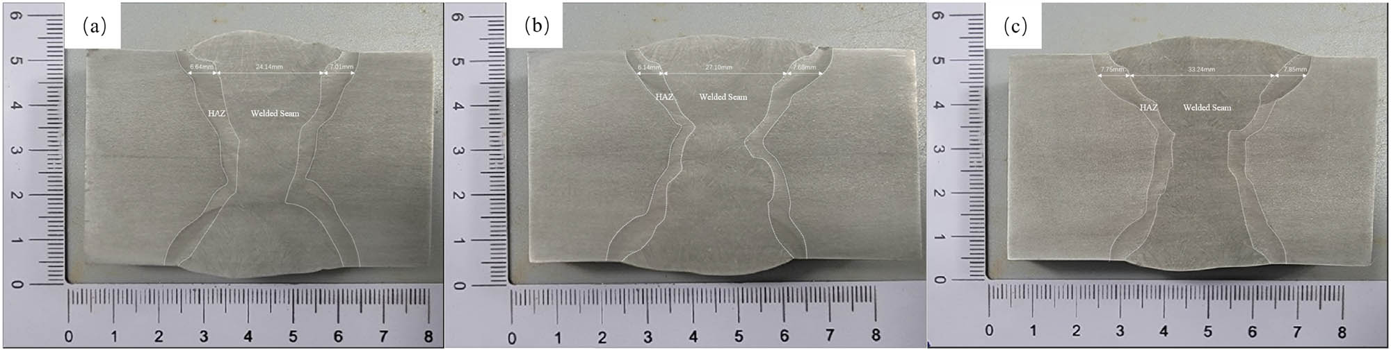
Cross-section of the welded joint at different heat input: (a) 22.5 kJ·cm−1, (b) 27.9 kJ·cm−1, and (c) 33.6 kJ·cm−1.
3.2 Effect of welding heat input on the microstructure of Q690qE joints
The microstructure of the coarse-grain zone (CGHAZ) at different heat input is shown in Figure 5a–c. As the retention time of the material in the high-temperature area increases, the original austenite grain size grows; after welding, the microstructure is mainly LB and GB, of which the content expands. When the welding heat input is 22.5 kJ·cm−1, the cooling rate is the fastest and the original austenite grain size is small, there being a small amount of martensite in the microstructure. As the welding heat input is 27.9 kJ·cm−1, the content of the martensite in the experimental steel microstructure decreases while GB increases. The microstructure consists predominantly of LB without almost martensite with the welding heat input of 33.6 kJ·cm−1. The microstructure of the fine-grain zone (FGHAZ) at different heat input is shown in Figure 5d–f. The boundary between the fine-grained zone and the coarse-grain zone is not as distinct as between the welded seam and the coarse-grain zone. As can be seen from Figure 5d–f, there exist less GB precipitates in the fine-grained region compared to the coarse-grain zone, and the microstructure is mainly composed of the acicular ferrite (AF), GB, and a small amount of bainite ferrite. With the welding heat input rising, more carbides gather and the size of the ferrite in the fine-grained region grows while GB and LB gradually decline.

Microstructure of coarse-grain zone and fine-grain zone of Q690qE joints at different heat input: (a)–(c) CGHAZ of 22.5, 27.9, and 33.6 kJ·cm−1; (d)–(f) FGHAZ of 22.5, 27.9, and 33.6 kJ·cm−1.
Based on the microstructure and continuous cooling transformation (CCT) curve shown in Figure 6, within the range of heat input selected for this experiment, the welded seam microstructure consists of F and GB.

(a) Microstructure of welded seam and (b) CCT of Q690qE.
3.3 EBSD analysis of the Q690qE joint
The inverse pole figure (IPF) map of welded seam and CGHAZ is shown in Figure 7. As shown in Figure 7, grains are cross-distributed in the welded seam, and with the increase in heat input, the size of the grains in the welded seam becomes larger. The grain size in the CGHAZ also increases with the increase in heat input and the grain orientation being relatively disordered. Upon comparison, it is observed that the average grain size in welded seam is smaller than that in CGHAZ.

EBSD IPF schematic diagram of the weld and CGHAZ at different heat input: (a)–(c) welded seam of 22.5, 27.9, and 33.6 kJ·cm−1; (d)–(f) CGHAZ of 22.5, 27.9, and 33.6 kJ·cm−1.
Figures 8 and 9, respectively, show the distribution of different grain boundaries in CGHAZ and the proportion of various grain boundaries. According to ref. [15], grain boundaries greater than 45° are beneficial for hindering crack propagation in CGHAZ. Therefore, the selected ranges for low and high angle grain boundaries in this study are 2°–15°, 15°–45°, and >45°. As shown in Figures 8 and 9, when the welding heat input is 33.6 kJ·cm−1, the number of grain boundaries >45° is at its lowest. In addition, when the welding heat input is 27.9 kJ·cm−1, the number of grain boundaries >45° is at its highest. But the number of grain boundaries less than 15° shows the opposite trend. The number of grain boundaries with orientations between 15° and 45° does not show significant changes with variations in heat input.

Schematic diagram of the distribution of grain boundaries in CGHAZ at different heat input: (a) 22.5 kJ·cm−1, (b) 27.9 kJ·cm−1, and (c) 33.6 kJ·cm−1.
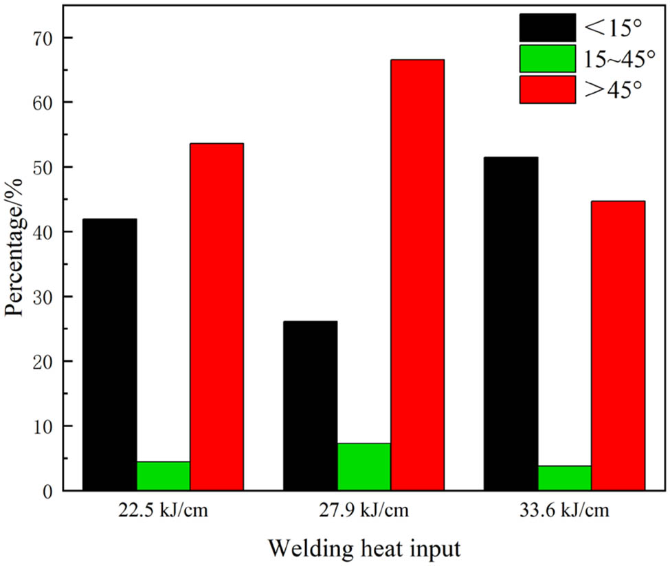
Grain boundary proportion diagram of coarse-grain zone size and misorientation angle.
3.4 Effect of welding heat input on mechanical properties
3.4.1 Hardness of cross-sections
The location of the hardness test is shown in Figure 10. Figure 11 shows the cross-sectional hardness distribution of Q690qE joints at different heat input. In the sub-critical HAZ near the PM, the ferrite grains become longer and larger and become dramatically coarsened and the hardness values is lower than that of the PM. The microstructure of the fine-grained region is composed of ferrite and a small quantity of GB, making the average hardness of fine-grained region hardness higher than that of the PM. In the coarse-grain zone, with the welding heat input increasing, the original austenite grain size and the content of GB content rise but the content of lath martensite and the hardness reduce.
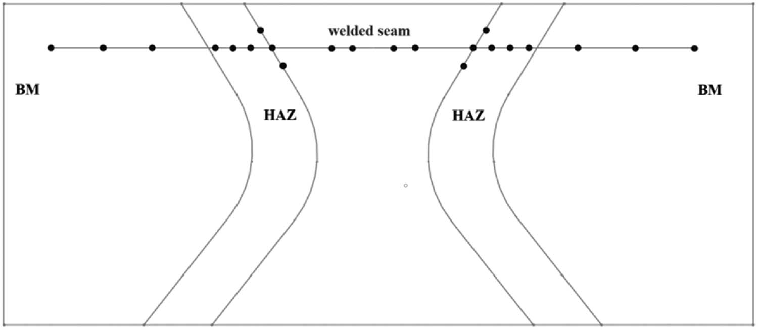
Schematic diagram of the microhardness test position in the welded joint microhardness test position.

Cross-sectional hardness distribution of Q690qE joints at different heat input.
3.4.2 Tensile properties
Table 4 indicates the tensile test results of Q690qE joints gained at the three SAW processes and the tensile test speed is 15 mm·min−1. The tensile test results imply that when the heat input is 22.5, 27.9, and 33.6 kJ·cm−1, the tensile strength of the joints is 824, 832, and 818 MPa, respectively. The fracture position of the tensile specimens are all at the PM under three different welding heat input, demonstrating that the tensile performance of joints is superior to that of the PM. Where with the heat input of 27.9 kJ·cm−1, the elongation after fracture of the joint has maximum tensile.
Tensile test results of Q690qE joints obtained at different heat input
| Heat input (kJ·cm−1) | Tensile strength of joints (MPa) | Yield strength of joints (MPa) | Fracture location | Elongation of welded seam (%) |
|---|---|---|---|---|
| 22.5 | 824 | 749 | PM | 20 |
| 27.9 | 832 | 717 | PM | 18 |
| 33.6 | 818 | 720 | PM | 16 |
3.4.3 Impact properties and fracture morphology
The −40°C low-temperature impact test results in different positions of the welded joints are shown in Table 5. Three experiments are conducted on samples in the same position and the average values are recorded. The average energy absorption values in the weld center for three welding processes are 138, 105, and 77 J, respectively; and the average values of impact absorption energy at the HAZ are 237, 242, and 102 J. The impact absorption energy of the HAZ of the joint is much higher than that of the center of the welded seam. With the increase in heat input, the size of ferrite grains in the welded seam increases, leading to a decrease in low-temperature impact toughness. When the heat input is 33.6 kJ·cm−1, the low-temperature impact performance of CGHAZ is the lowest, which is related to the decrease in the number of grain boundaries with angles greater than 45° as analyzed earlier by EBSD.
Impact test results of Q690qE joints in various positions at different heat input
| Heat input (kJ·cm−1) | Notch position | Impact absorption energy (J) | Average value (J) | Standardized requirements (J) |
|---|---|---|---|---|
| 22.5 | Weld center | 142/133/139 | 138 | ≥60 |
| HAZ | 242/231/235 | 237 | ≥60 | |
| 27.9 | Weld center | 91/109/116 | 105 | ≥60 |
| HAZ | 253/232/243 | 242 | ≥60 | |
| 33.6 | Weld center | 83/69/79 | 77 | ≥60 |
| HAZ | 113/93/100 | 102 | ≥60 |
Figure 12 gives the low temperature impact fracture morphology of the welded joints. In Figure 12a–c, the low-temperature impact fracture in the welded seam with a heat input of 22.5 and 27.9 kJ·cm−1 is significantly ductile, consisting mainly of fine dimples that contain inclusions and are relatively deep, demonstrating good toughness. When the heat input increases to 33.6 kJ·cm−1, the fracture morphology at the center of the weld shows obvious transcrystalline rupture with river patterns, resulting in poorer impact properties. As shown in Figure 12d–f, at the fusion line, the morphology of the low-temperature impact fracture is primarily characterized by cleavage steps, tear ridges, and small dimples. As the heat input is raised to 33.6 kJ·cm−1, the cleavage steps become larger and the number of small dimples decreases, leading to a marked reduction in impact performance.

Fracture morphology of welded joints at different heat input: (a)–(c) welded seam of 22.5, 27.9, and 33.6 kJ·cm−1; (d)–(f) CGHAZ of 22.5, 27.9, and 33.6 kJ·cm−1.
4 Conclusion
The analysis of the microstructure and mechanical properties of submerged arc welded joints of 40 mm thick Q690qE resulted in the following conclusions:
Full penetration and no defects welded joints were obtained using SAW with the heat input within the range of 22.5–33.6 kJ·cm−1. The amount of the welding heat input has a positive correlation with the width of the HAZ.
The microstructure in the coarse-grain zone mainly includes LB, lath martensite, and GB. As the heat input increases, the microstructure consists mainly of LB, almost without martensite, and the hardness decreases. The microstructure of the fine-grain zone mainly comprised AF, GB and a small amount of LB, the change in hardness is not significant.
The joints being stretched, fracture occurs in the PM. The elongation of the weld metal after fracture gradually declines as the weld heat input increases. The tensile strength is the highest when the heat input is 27.9 kJ·cm−1, with a tensile strength of 832 MPa. Low-temperature impact toughness tests indicate that the impact toughness at the center of the welded seam decreases with an increase in heat input. The low-temperature impact absorption energy in the HAZ dramatically drops when the heat input is 33.6 kJ·cm−1.
Based on the microstructural analysis and EBSD tests, the reason for the abrupt decline in the weld’s low-temperature impact toughness at a heat input of 33.6 kJ·cm−1 is due to the enlargement of the grain size of AF. The decrease in low-temperature impact toughness at the fusion line is related to the reduction in the number of grain boundaries with angles greater than 45° in the coarse-grain zone.
Acknowledgements
This research was supported by the National Natural Science Foundation of China [grant number 52001141 & 52475360], Jiangsu Province Science and Technology Achievement Transformation Special Funds (BA2021069) and the Jiangsu Province Undergraduate Innovation Project (No. SJCX23_2184).
-
Funding information: This research was supported by Jiangsu Province Science and Technology Achievement Transformation Special Funds (BA2021069) and the Jiangsu Province Undergraduate Innovation Project (No. SJCX23_2184).
-
Author contributions: Wen Huang: writing – original draft, writing – review & editing, methodology, formal analysis; Kai Qi: conceptualization, formal analysis, funding acquisition, methodology, supervision, validation; Zhigang Liu: formal analysis, methodology; Liang Yang: resources, software; Zheyan Xue: conceptualization, formal analysis, methodology; Taotao Li: resources, supervision; Xiaoqiang Zhang: software, validation; Ruifeng Li: supervision, validation.
-
Conflict of interest: Authors state no conflict of interest.
-
Data availability statement: The raw/processed data required to reproduce these findings cannot be shared at this time as the data also forms part of an ongoing study.
References
[1] Cui, B., Z. W. Liu, Z. Liu, M. D. Peng, M. Y. Shi, Q. B. Du, et al. Effect of welding heat input on microstructural evolution and impact toughness of the simulated coarse-grained heat-affected zone of Q960 steel. Journal of Welding in the World, Vol. 67, No. 1, 2023, pp. 235–249.10.1007/s40194-022-01413-2Search in Google Scholar
[2] Homma, K., M. Tanaka, K. Matsuoka, T. Kasuya, and H. Kawasaki. Development of application technologies for bridge high performance steel, BHS. Journal of Nippon Steel Technical Report, Vol. 97, 2008, pp. 51–57.Search in Google Scholar
[3] Hirohata, M. Material properties and weldability of steels used in aged bridges. Journal of the Iron and Steel Institute of Japan, Vol. 103, No. 11, 2017, pp. 21–27.10.2355/tetsutohagane.TETSU-2017-021Search in Google Scholar
[4] Nowacki, J., A. Sajek, and P. Matkowski. The influence of welding heat input on the microstructure of joints of S1100QL steel in one-pass welding. Journal of Archives of Civil and Mechanical Engineering, Vol. 16, No. 4, 2016, pp. 777–783.10.1016/j.acme.2016.05.001Search in Google Scholar
[5] Zhang, C. G., P. M. Lu, and X. Z. Hu. Residual stress and softening in welded high-strength low-alloy steel with a buffering layer. Journal of Materials Processing Technology, Vol. 214, No. 2, 2014, pp. 229–237.10.1016/j.jmatprotec.2013.09.002Search in Google Scholar
[6] Perka, A. K., M. John, and U. B. Kuruveri. Advanced high strength steels for automotive applications: arc and laser welding process, properties, and challenges. Journal of Metals, Vol. 12, No. 2, 2022, id. 1051.10.3390/met12061051Search in Google Scholar
[7] Zhang, L., Y. J. Li, J. Wang, and Q. L. Jiang. Effect of acicular ferrite on cracking sensibility in the weld metal of Q690 + Q550 high strength steels. Journal of ISIJ International, Vol. 51, No. 7, 2011, pp. 1132–1136.10.2355/isijinternational.51.1132Search in Google Scholar
[8] Jiang, M. Z., Y. C. Yu, and H. Li. Effect of rare earth cerium addition on microstructures and mechanical properties of low carbon high manganese steels. Journal of High Temperature Materials and Processes, Vol. 36, No. 2, 2017, pp. 145–153.10.1515/htmp-2015-0183Search in Google Scholar
[9] Ashari, R., A. Eslami, and M. Shamanian. Effect of weld heat input on corrosion of dissimilar welded pipeline steels under simulated coating disbondment protected by cathodic protection. Journal of Materials Research and Technology, Vol. 9, No. 2, 2020, pp. 2136–2145.10.1016/j.jmrt.2019.12.044Search in Google Scholar
[10] Lei, J., D. H. Yang, and Z. T. Wang. The corrosion resistance of weathering bridge steel in industrial environment. Journal of Highway, Vol. 65, No. 11, 2020, id. 331.Search in Google Scholar
[11] Yu, Q. M. Specimen’s short fatigue crack fabricationest for Q420qe. Journal of Advanced Materials Research, Vol. 239, No. 3, 2013, pp. 711–713.10.4028/www.scientific.net/AMR.711.107Search in Google Scholar
[12] Chen, C., W. Wang, D. Li, Y. Cai, Y. Zhang, and K. Zhang. Effect of beam oscillation on microstructure and properties of laser-TIG hybrid welding of D406a ultra-high strength steel. Journal of Manufacturing Processes, Vol. 57, 2020, pp. 798–805.10.1016/j.jmapro.2020.07.048Search in Google Scholar
[13] Lei, D., X. Yin, Z. Yuan, and J. Wen. Heat lnput on microstructure and properties of weld joints of 800MPa grade high strength low alloy steel. Journal of Hot Working Technology, Vol. 44, No. 1, 2015, pp. 36–38.Search in Google Scholar
[14] Du, W., P. Che, and J. Wu. Welding technology of high performance bridge steel Q690qE. Journal of Welding Technology, Vol. 50, No. 6, 2021, pp. 24–28.Search in Google Scholar
[15] Wang, X. Study on strengthening and toughening of coarse-grained heat-affected zone of Q690 bridge steel. Journal of Railway Construction Technology, Vol. 3, 2023, pp. 35–39.Search in Google Scholar
[16] Shin, Y. T., S. W. Kang, and H. W. Lee. Fracture characteristics of TMCP and QT steel weldments with respect to crack length. Journal of Materials Science & Engineering A, Vol. 434, 2006, pp. 365–371.10.1016/j.msea.2006.07.076Search in Google Scholar
[17] Wang, X. L., Y. R. Nan, and Z. J. Xie. Influence of welding pass on microstructure and toughness in the reheated zone of multi-pass weld metal of 550 MPa off shore engineering steel. Journal of Materials Science & Engineering A, Vol. 702, 2017, pp. 196–205.10.1016/j.msea.2017.06.081Search in Google Scholar
[18] Celin, R. and J. Burja. Effect of cooling rates on the weld heat affected zone coarse grain microstructure. Journal of Metallurgical and Materials Engineering, Vol. 24, No. 1, 2018, pp. 37–44.10.30544/342Search in Google Scholar
© 2024 the author(s), published by De Gruyter
This work is licensed under the Creative Commons Attribution 4.0 International License.
Articles in the same Issue
- Research Articles
- De-chlorination of poly(vinyl) chloride using Fe2O3 and the improvement of chlorine fixing ratio in FeCl2 by SiO2 addition
- Reductive behavior of nickel and iron metallization in magnesian siliceous nickel laterite ores under the action of sulfur-bearing natural gas
- Study on properties of CaF2–CaO–Al2O3–MgO–B2O3 electroslag remelting slag for rack plate steel
- The origin of {113}<361> grains and their impact on secondary recrystallization in producing ultra-thin grain-oriented electrical steel
- Channel parameter optimization of one-strand slab induction heating tundish with double channels
- Effect of rare-earth Ce on the texture of non-oriented silicon steels
- Performance optimization of PERC solar cells based on laser ablation forming local contact on the rear
- Effect of ladle-lining materials on inclusion evolution in Al-killed steel during LF refining
- Analysis of metallurgical defects in enamel steel castings
- Effect of cooling rate and Nb synergistic strengthening on microstructure and mechanical properties of high-strength rebar
- Effect of grain size on fatigue strength of 304 stainless steel
- Analysis and control of surface cracks in a B-bearing continuous casting blooms
- Application of laser surface detection technology in blast furnace gas flow control and optimization
- Preparation of MoO3 powder by hydrothermal method
- The comparative study of Ti-bearing oxides introduced by different methods
- Application of MgO/ZrO2 coating on 309 stainless steel to increase resistance to corrosion at high temperatures and oxidation by an electrochemical method
- Effect of applying a full oxygen blast furnace on carbon emissions based on a carbon metabolism calculation model
- Characterization of low-damage cutting of alfalfa stalks by self-sharpening cutters made of gradient materials
- Thermo-mechanical effects and microstructural evolution-coupled numerical simulation on the hot forming processes of superalloy turbine disk
- Endpoint prediction of BOF steelmaking based on state-of-the-art machine learning and deep learning algorithms
- Effect of calcium treatment on inclusions in 38CrMoAl high aluminum steel
- Effect of isothermal transformation temperature on the microstructure, precipitation behavior, and mechanical properties of anti-seismic rebar
- Evolution of residual stress and microstructure of 2205 duplex stainless steel welded joints during different post-weld heat treatment
- Effect of heating process on the corrosion resistance of zinc iron alloy coatings
- BOF steelmaking endpoint carbon content and temperature soft sensor model based on supervised weighted local structure preserving projection
- Innovative approaches to enhancing crack repair: Performance optimization of biopolymer-infused CXT
- Structural and electrochromic property control of WO3 films through fine-tuning of film-forming parameters
- Influence of non-linear thermal radiation on the dynamics of homogeneous and heterogeneous chemical reactions between the cone and the disk
- Thermodynamic modeling of stacking fault energy in Fe–Mn–C austenitic steels
- Research on the influence of cemented carbide micro-textured structure on tribological properties
- Performance evaluation of fly ash-lime-gypsum-quarry dust (FALGQ) bricks for sustainable construction
- First-principles study on the interfacial interactions between h-BN and Si3N4
- Analysis of carbon emission reduction capacity of hydrogen-rich oxygen blast furnace based on renewable energy hydrogen production
- Just-in-time updated DBN BOF steel-making soft sensor model based on dense connectivity of key features
- Effect of tempering temperature on the microstructure and mechanical properties of Q125 shale gas casing steel
- Review Articles
- A review of emerging trends in Laves phase research: Bibliometric analysis and visualization
- Effect of bottom stirring on bath mixing and transfer behavior during scrap melting in BOF steelmaking: A review
- High-temperature antioxidant silicate coating of low-density Nb–Ti–Al alloy: A review
- Communications
- Experimental investigation on the deterioration of the physical and mechanical properties of autoclaved aerated concrete at elevated temperatures
- Damage evaluation of the austenitic heat-resistance steel subjected to creep by using Kikuchi pattern parameters
- Topical Issue on Focus of Hot Deformation of Metaland High Entropy Alloys - Part II
- Synthesis of aluminium (Al) and alumina (Al2O3)-based graded material by gravity casting
- Experimental investigation into machining performance of magnesium alloy AZ91D under dry, minimum quantity lubrication, and nano minimum quantity lubrication environments
- Numerical simulation of temperature distribution and residual stress in TIG welding of stainless-steel single-pass flange butt joint using finite element analysis
- Special Issue on A Deep Dive into Machining and Welding Advancements - Part I
- Electro-thermal performance evaluation of a prismatic battery pack for an electric vehicle
- Experimental analysis and optimization of machining parameters for Nitinol alloy: A Taguchi and multi-attribute decision-making approach
- Experimental and numerical analysis of temperature distributions in SA 387 pressure vessel steel during submerged arc welding
- Optimization of process parameters in plasma arc cutting of commercial-grade aluminium plate
- Multi-response optimization of friction stir welding using fuzzy-grey system
- Mechanical and micro-structural studies of pulsed and constant current TIG weldments of super duplex stainless steels and Austenitic stainless steels
- Stretch-forming characteristics of austenitic material stainless steel 304 at hot working temperatures
- Work hardening and X-ray diffraction studies on ASS 304 at high temperatures
- Study of phase equilibrium of refractory high-entropy alloys using the atomic size difference concept for turbine blade applications
- A novel intelligent tool wear monitoring system in ball end milling of Ti6Al4V alloy using artificial neural network
- A hybrid approach for the machinability analysis of Incoloy 825 using the entropy-MOORA method
- Special Issue on Recent Developments in 3D Printed Carbon Materials - Part II
- Innovations for sustainable chemical manufacturing and waste minimization through green production practices
- Topical Issue on Conference on Materials, Manufacturing Processes and Devices - Part I
- Characterization of Co–Ni–TiO2 coatings prepared by combined sol-enhanced and pulse current electrodeposition methods
- Hot deformation behaviors and microstructure characteristics of Cr–Mo–Ni–V steel with a banded structure
- Effects of normalizing and tempering temperature on the bainite microstructure and properties of low alloy fire-resistant steel bars
- Dynamic evolution of residual stress upon manufacturing Al-based diesel engine diaphragm
- Study on impact resistance of steel fiber reinforced concrete after exposure to fire
- Bonding behaviour between steel fibre and concrete matrix after experiencing elevated temperature at various loading rates
- Diffusion law of sulfate ions in coral aggregate seawater concrete in the marine environment
- Microstructure evolution and grain refinement mechanism of 316LN steel
- Investigation of the interface and physical properties of a Kovar alloy/Cu composite wire processed by multi-pass drawing
- The investigation of peritectic solidification of high nitrogen stainless steels by in-situ observation
- Microstructure and mechanical properties of submerged arc welded medium-thickness Q690qE high-strength steel plate joints
- Experimental study on the effect of the riveting process on the bending resistance of beams composed of galvanized Q235 steel
- Density functional theory study of Mg–Ho intermetallic phases
- Investigation of electrical properties and PTCR effect in double-donor doping BaTiO3 lead-free ceramics
- Special Issue on Thermal Management and Heat Transfer
- On the thermal performance of a three-dimensional cross-ternary hybrid nanofluid over a wedge using a Bayesian regularization neural network approach
- Time dependent model to analyze the magnetic refrigeration performance of gadolinium near the room temperature
- Heat transfer characteristics in a non-Newtonian (Williamson) hybrid nanofluid with Hall and convective boundary effects
- Computational role of homogeneous–heterogeneous chemical reactions and a mixed convective ternary hybrid nanofluid in a vertical porous microchannel
- Thermal conductivity evaluation of magnetized non-Newtonian nanofluid and dusty particles with thermal radiation