Design and 3D simulation of open topping-on structured crochet fabric
-
Buqing Sun
 ,
Shukai Tang
,
Shukai Tang

Abstract
In order to reduce the development cost of open topping-on structured crochet fabrics and realize the diversified design and three-dimensional (3D) simulation of fabric, the weaving process and principle of this kind of fabric were deeply studied, and the lapping motion and yarn threading motion models of fabric structure were established. Combined with the structural characteristics of fabric, the geometric models of pillar stitch organization, weft lining organization, open topping-on organization, and fringed weft-insertion organization were established under ideal conditions. Through the measurement and analysis of the actual fabric, the number and position of the coil type value points are further determined. The shape transformation of the fringes is realized by combining the random geometric transformation algorithm. This work introduces the structural characteristics and process design method of a typical fabric, and explores the diversified combination of structures, and finally realizes the 3D simulation of fabric with the help of JavaScript and C# computer programming language. The results show that, through 3D simulation technology, we can quickly try different patterns, materials, and color combinations, so as to see the design effect intuitively. This way of virtual display and iterative modification can significantly improve the design efficiency, and greatly reduce the trial and error cost and time consumption, providing an efficient way to find the best design scheme.
1 Introduction
Crocheted lace trim fabric, as a specialized subset of warp-knitted textiles, is predominantly characterized by its narrow-width configuration. Technically derived from the Raschel knitting mechanism, modern crochet machines represent an advanced evolution of traditional warp-knitting technology. As a traditional textile product, crocheted lace trim fabric has wide application value in the field of clothing and home textile decoration. In recent years, with the rapid development of computer-aided design technology, three-dimensional (3D) simulation modeling has played a key role in the design and optimization process of crochet sash, but the research of 3D simulation modeling of this fabric is still in the exploration stage, so the realization of 3D simulation of crochet lace trim fabric is the focus of current research.
Since the 1920s, the research on simulation models of textile structures has progressively evolved from two-dimensional (2D) planar models to 3D models and texture simulations. Zheng and Liu [1] conducted a numerical study on the influence of the mesh structure and yarn structure of typical 3D mesh fabrics during the shaping process by establishing a yarn-level finite element model reconstructed based on micro-X-ray computed tomography. Mozafary and Payvandy [2] used the FAST system to measure the effective parameters affecting the drape performance of the fabric, reduce the error value between the simulated fabric behavior and the actual behavior, and optimize the parameters of the mass-spring model by applying particle swarm optimization. Seçkin [3] proposed a method aimed at improving texture detection and weaving parameter prediction in the textile industry by establishing a dataset in which textile images are manually labeled for texture, specific quality, weft, and warp parameters. Liu and Kyosev [4] proposed a rendering method based on the fiber level to simulate different yarns and fabrics.
At present, while studies on crocheted lace trim fabrics have achieved considerable depth in process analysis, simulation research remains limited to 2D approaches. Mao [5,6,7] conducted systematic classifications of crocheted machines and fabrics, analyzing their knitting principles and process parameters with accompanying structural diagrams, yet failed to develop 3D simulations. Gong [8] employed Microsoft Visual C++ 6.0 to establish mathematical models of lapping movements and geometric models of topping-on and chain structures. Using Bézier curves as fitting functions, they achieved 2D simulations with parameter-controlled topping-on structures, though the eventual 3D simulation of topping-on crocheted fabrics demonstrated limited visual fidelity. The CAD software COMEZ DRAW3 developed by COMEZ company in Italy can be used for the drawing of COMEZ electronic machine and mechanical control machine (slide chain), which can draw the lapping yarn movement diagram of the topping-on structure by selecting a specific machine model, the software only displays 2D representations without 3D simulation capabilities. Although these studies have not realized effective 3D simulation, they have analyzed the knitting principle and process parameters of crochet lace trim fabric, which provided the process basis for 3D simulation.
This study presents a design methodology for a specialized category of crocheted lace trim fabrics – specifically open topping-on structured crocheted fabric, essentially constituting a unique type of warp-knitted weft-insertion structure. By analyzing the relationship between stopper pin and knitting needle, a mathematical model of lapping movement and yarn threading is established, together with a geometric model for loop formation, and the fringed structure is deformed by matrix transformation, finally the 3D simulation of the fabric is realized. In order to directly observe the fabric structure and appearance effect, so as to improve the efficiency of product design.
2 Process and structural characteristics
The open topping-on structure and fringe structure of warp-knitted open topping-on fabrics represent special weft-insertion configurations. The looped structure is formed by the weft yarn’s circular motion enabled by the stopper pin, while the fringe lace structure is created through weft yarn positioning by fixed weft hooks at the fringe formation point [9], driven by the weft needles. The pillar stitch construction is completed through the movement of latch needles.
2.1 Knitting principle
As shown in Figure 1, the position of each stopper pin is precisely controlled by the stopper mechanism through mechanical or electronic control systems. The lapping movement is achieved through coordinated timing of extension and retraction movements of the stopper pins with positional and trajectory variations of the guide needles, resulting in the formation of weft-insertion structures with specific lengths and configurations. In the warp knitting machine, more versatile loop geometries are enabled by the application of stopper pins through weft yarn motion, whereby aesthetically varied, highly decorative crochet fabrics with superior shape definition are produced.
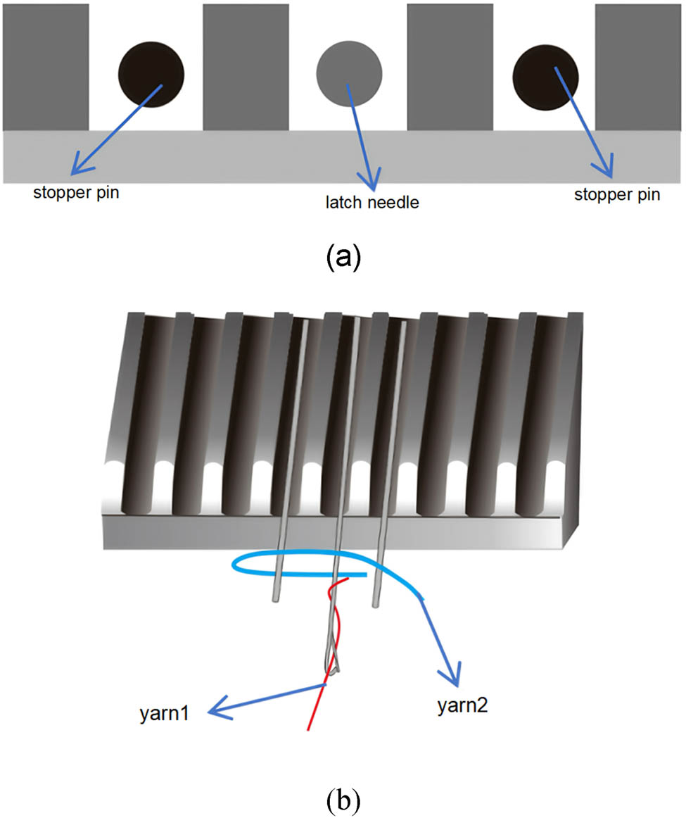
The Structure of stitch-forming mechanisms: (a) Front view and (b) top view.
The latch needle is composed of a cylindrical or flat-cross-sectioned needle shaft and a movable latch. A needle hook is formed at the apex of the shaft, while the latch is rotatably connected to the shaft through a hinge mechanism, enabling free oscillation for hook opening/closing. Due to the self-acting property of the latch mechanism, yarn feeding during lapping is not directionally restricted, allowing bilateral yarn insertion (both left and right sides). Consequently, more complex knitting trajectories can be accommodated, through which either open or closed loop structures are formed.
Wavy fringe lace is primarily produced through variable strokes of the weft-insertion guide bar, by which fringe loops of varying lengths are formed at the selvage edges. At the weft-turning points, positioning hooks must be employed to prevent yarn displacement, where the positioning hooks and weft-insertion mechanism are required to be precisely coordinated [10].
2.2 Knitting process of open topping-on structures
This fabric is primarily formed through synchronized coordination between knitting needles and stopper mechanisms in the timing sequence. Two sets of stopper mechanisms are required to construct looped structures on both left and right sides, which are then consolidated by pillar stitches. The open topping-on structure process is described as follows:
First, both stopper pins are simultaneously extended, and yarn 2 (Figure 1) is wrapped around the stopper pins for one complete cycle by the yarn guide device to form the lower loop structure. Meanwhile, yarn 1 (Figure 1) is normally knitted into the first pillar stitch according to the knitting timing sequence.
Subsequently, both stopper pins are simultaneously retracted, causing yarn 2 (Figure 1) to be wrapped around the knitting needles, thereby forming the upper loop structure. Concurrently, yarn 1 (Figure 1) is successively knitted into the second, third, and fourth pillar stitches according to the programmed sequence.
The open topping-on structure is consolidated by the ground yarn through pillar stitch formation. By repeating the aforementioned steps, the left open topping-on structure is completed.
3 Mathematical modeling
The crochet structure serves as the foundation for both the appearance and performance of warp-knitted fabrics, being primarily determined by the number of guide bars, the lateral movements of guide needles, and the threading patterns [11]. To facilitate effective computer-aided design and simulation of such open topping-on crochet fabrics, the establishment of a corresponding process matrix model is required.
During the design of open topping-on crochet fabrics, the lapping movement diagram of guide bars is typically first drafted on point paper, followed by the recording of its lapping numerical sequence. The lapping sequence describes the yarn’s lapping trajectory, where the lateral movements of guide needles at each course are systematically documented in sequential order [12].
For this fabric type, the lapping numerical sequence is designed following warp knitting principles, where the lateral movements of yarns at the needle front are systematically recorded as the lapping code. Figure 2 depicts the lapping movement of the open topping-on crochet fabric, the lapping sequences for the six guide bars (from left to right) are respectively:
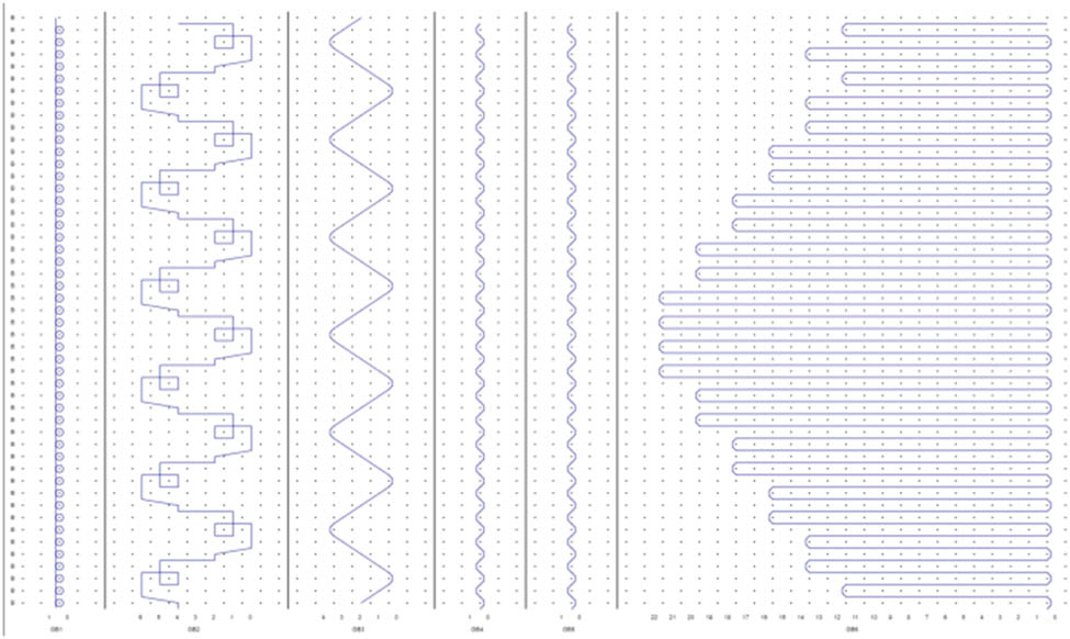
Lapping diagram.
GB1:1-0/1-0/1-0/1-0/1-0/1-0/1-0/1-0//;
GB2:4-4/6-4/5-5/5-4/2-2/0-2/1-1/1-2//;
GB3:2-2/1-1/0-0/1-1/2-2/3-3/4-4/3-3//;
GB4:0-0/1-1/0-0/1-1/0-0/1-1/0-0/1-1//;
GB5:0-0/1-1/0-0/1-1/0-0/1-1/0-0/1-1//;
GB6:0-0/12-12/0-0/14-14/0-0/14-14/0-0/16-16/0-0/16-16/0-0/18-18/0-0/18-18/0-0/20-20/0-0/20-20/0-0/22-22/0-0/22-22/0-0/22-22/0-0/22-22/0-0/20-20/0-0/20-20/0-0/18-18/0-0/18-18/0-0/16-16/0-0/16-16/0-0/14-14/0-0/14-14/0-0/12-12/0-0/14-14/0-0/12-12//.
From the lapping sequence, GB1 is identified as a standard warp-knitting guide bar, with its knitting motion forming pillar stitches. GB2 is determined to be the open topping-on guide bar. Based on both physical fabric examination and machine operation observations, the completion of one topping-on structure is temporally synchronized with four pillar stitch formations. This structural correspondence is achieved through precise timing control of the lapping sequence in the looped structure relative to the pillar stitch configuration. GB3, GB4, and GB5 are designated as weft-insertion guide bars, while GB6 is classified as the fringe weft-insertion guide bar. To facilitate notation and programming implementation, an open topping-on lapping sequence model is constructed based on warp-knitting numerical design principles. In the lapping sequence of the second guide bar (GB2), “4-4” is defined to represent weft insertion; “6-4” indicates the needle-front lateral movement position for lower loop structure; and “2-1” specifies the needle-front lateral movement position for upper loop structure.
3.1 Mathematical model of lapping numerical sequence
In the lapping diagram, a continuous line is used to represent the movement trajectory of the yarn threaded through a single guide needle across multiple courses [13]. The lapping numerical model is generally expressed using a single-needle-bed notation system, where a numerical matrix is defined in equation (1) to represent the lapping sequence.
where i ∈ {1, 2, 3, …, I}, i represents the guide bar number; j ∈ {1, 2, 3,…, m}, j denotes the course number in the repeat pattern; and u ∈ {1, 2, 3, …, n}, u indicates the number of fully threaded yarns. Since two digits represent the lapping movement of one course, the lapping motion of a single yarn is described by two columns of digits. Here P(i,j,u) represents the lapping digit of the uth yarn on the ith guide bar for the j course. For example, i = 1, j = 1, p i,1,1 and p i,1,2 denote the two lapping digits of the first yarn in the first course during its lapping motion.
For the types of loops, when p i,j,2u − p i,j,2u−1 = 0, the loop type is a Weft-insertion loop; when |p i,j,2u − p i,j,2u−1| = 1, the loop type is categorized as either standard knitted loops or upper loop structure of open topping-on structures; and when ∣p i,j,2u − p i,j,2u−1∣ = 2, the loop type is identified as the lower loop structure of an open topping-on structure. Open loops are formed when lapping movements in the needle front and needle back directions are identical, or when needle-front lapping occurs with zero lateral movement at the needle back. Conversely, closed loops are produced when opposing lapping directions are executed between the needle front and needle back [14]. It follows that when (p i,j,2u − p i,j,2u−1) × (p i,j−1,2u − p i,j,2u ) ≥ 0, the loop is an open loop. When (p i,j,2u − p i,j,2u−1) × (p i,j − 1,2u − p i,j,2u ) < 0, the loop is a closed loop.
Regarding the guide bar shogging movement, taking the lapping digits of the first yarn as an example, H(i,j,1) = p i,j,1 − p i,j−1,2. Here H(i,j,1) represents the direction and magnitude of the back shog for the ith guide bar at the jth course. If H(i,j,1) > 0, it indicates that the ith guide bar performs a back shog from right to left at the jth course. Conversely, if H(i,j,1) < 0, it means the ith guide bar executes a back shog from left to right at the jth course. When H(i,j,1) = 0, no back shogging occurs. The absolute value ∣H(i,j,1)∣ denotes the distance of the back shog.
3.2 Mathematical model of yarn threading
The threading arrangement diagram is utilized to describe the yarn threading status of each guide needle on the guide bars. During process design, the lapping numerical sequence for needle-front lateral movements at each course is composed of two digits, necessitating the horizontal expansion of each yarn’s threading information across two wales. With individual yarns as units, the threading configuration is represented by a block matrix C(i,j) as formulated in equation (2).
where i ∈ {1, 2, 3, …, I}, i represents the guide bar number; j ∈ {1, 2, 3, …, m}, j denotes the course number in the repeat pattern; and u ∈ {1, 2, 3, …, n}, u indicates the number of fully threaded yarns. C(i, j, k) is constructed as the threading sub-matrix for the kth yarn on the ith guide bar, as formulated in equation (3).
where c i,j,2k–1 and c i,j,2k represent the threading condition of the kth yarn on the ith guide bar at the jth course of the front needle bed. Within the block sub-matrix C(i, j, k), all elements share the same value (either 0 or 1), determined by the yarn’s threading state.
Taking the threading configuration of the first guide bar (GB1) in Table 3 as an example, when the number of courses is specified as j = 2, the threading matrix is constructed as follows:
The symbolic representation method is as follows: GB1: 3A, 1*, 1A, 2*, 1A, 1*, 3A, 10* or in abbreviated form: GB1: 3-in-1 empty, 1-in-2 empty, 1-in-1 empty, and 3-in-10 empty. The alphabetic characters (A–Z) are designated to represent different yarn types.
4 Geometric model
The open topping-on structured crochet fabric is composed of multiple weft-insertion structures and pillar stitch constructions. Therefore, separate loop models are established for each structural component.
4.1 Pillar stitch loop model
Pillar stitch loops are modeled through the following computational process: Key points from physical specimens are measured, and type-value points are programmatically defined. Bézier curve fitting is then applied to generate smooth loop profiles. The fabric structure is consolidated using pillar stitch organization, with the loop model illustrated in Figure 3. Eight control points (S₀–S 7) are utilized to construct individual loops, where h is defined as the loop height and w as the loop spacing.
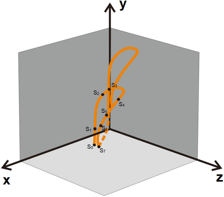
Pillar stitch loop model.
4.2 Standard weft-insertion structure model
Since no needle-front lapping is performed by the weft-insertion guide bars (with only needle-back lapping executed), the yarns are clamped between the main bodies and underlaps of the loop-forming stitches [15]. In open topping-on structure fabrics, all weft-insertion structures are consolidated by pillar stitches to form complete constructions, as illustrated in Figure 4. Through physical measurements, a two-point weft-insertion model is established as shown in Figure 5.
Physical diagram of weft-insertion loops.
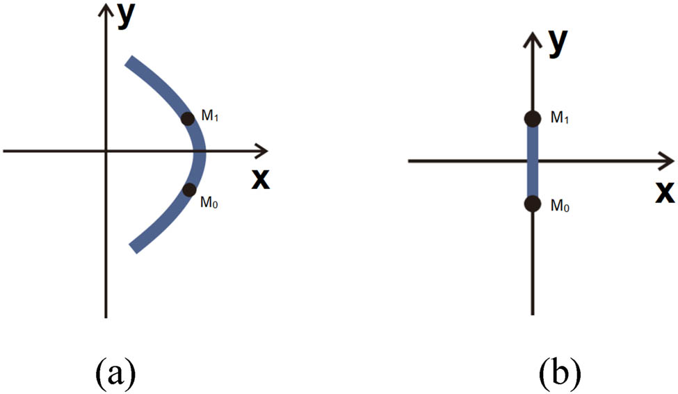
Weft-insertion loop model: (a) Front view and (b) side view.
4.3 Open topping-on structure model
This structure is recognized as one of the more complex configurations in crochet fabrics. Initially, an idealized loop geometric model is established based on its physical morphology. Through combined analysis with actual fabric measurements, the number and positions of loop type-value points are subsequently determined.
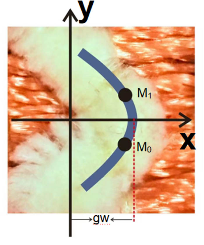
In this study, microscopic measurements are employed to determine loop structural dimensions, with comprehensive high-magnification observation and metrological analysis of the fabric’s surface morphology being conducted to satisfy loop measurement requirements. To enhance measurement accuracy and minimize errors caused by yarn type and diameter variations, dimensional measurements are referenced to yarn centerlines [16]. As shown in Figure 6, through systematic observation of these loop structures’ variation patterns, the 3D model of lower loops in open topping-on structures is constructed with six type-value points, while upper loops are represented by six type-value points.
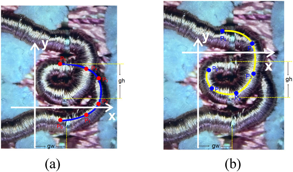
Physical diagram of open topping-on crochet fabric: (a) Lower loop structure and (b) upper loop structure.
When pillar stitches are fully threaded, the distance between two adjacent pillar stitches is defined as gw, the height of a single pillar stitch loop as gh, and the loop radius as d. During type-value point determination, the coordinate system is first established based on entry and exit point coordinates. The positions of all type-value points are then calculated through the proportional distance relationships and positional references to the pillar stitch organization, ultimately generating the loop geometric model.
The loops are categorized into left loops and right loops. Taking the right loop as an example (as shown in Figure 6), it is divided into the lower loop structure and upper loop structure.
For the lower loop arc structure, the type-value points are designated as P 0 to P 5, with their x-coordinates defined as P 0x to P 5x , y-coordinates as P 0y to P 5y , and z-coordinates as P 0z to P 5z . Similarly, for the upper loop structure, the type-value points are assigned as Q 0 to Q 5, with their x-coordinates specified as Q 0x to Q 5x , y-coordinates as Q 0y to Q 5y , and z-coordinates as Q 0z to Q 5z . The grid point width and height are established as gw and gh, respectively. The coordinates of all type-value points are systematically presented in Table 1.
Type value point of open topping-on structured crochet fabric
| Type-value points | X/mm | Y/mm | Z/mm |
|---|---|---|---|
| P 0 | 0.75 × gw | −0.6 × gh | 0 |
| P 1 | 2.0 × gw | −0.4 × gh | 0 |
| P 2 | 2.6 × gw | 0.1 × gh | 0 |
| P 3 | 2.6 × gw | 1.1 × gh | 0 |
| P 4 | 2.0 × gw | 1.75 × gh | 0 |
| P 5 | 0.75 × gw | 1.75 × gh | 0 |
| Q 0 | 0.35 × gw | 1.35 × gh | 0 |
| Q 1 | 0.4 × gw | 0.75 × gh | 0 |
| Q 2 | 1.15 × gw | 0.6 × gh | 0 |
| Q 3 | 1.65 × gw | 0.9 × gh | 0 |
| Q 4 | 1.55 × gw | 2.3 × gh | 0.5 × d |
| Q 5 | 0.75 × gw | 2.75 × gh | 0.6 × d |
Based on the type-value points in Table 1, the loop model shown in Figure 7 is constructed.
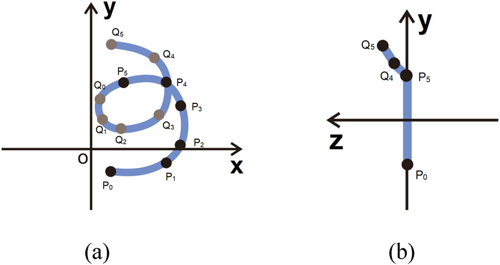
The model of open topping-on crochet fabric physical picture: (a) Front view and (b) side view.
4.4 Fringe structure model
As shown in Figure 8, based on the analysis of the fringe structure’s morphology and knitting principles, the edge formation is achieved by increasing the number of type-value points on the weft-insertion loops. An idealized loop model is then constructed.
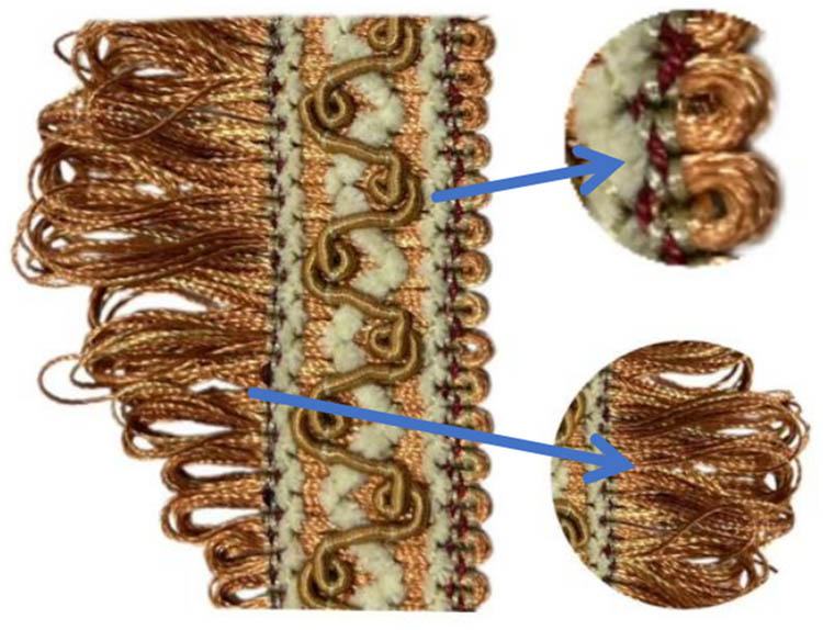
Physical diagram of fringe loops.
Considering the relative length–width relationship of fringe weft-insertion loops, as exemplified by the lapping sequence “12-12, 18-18”, the fringe structure is characterized where the fringe length is defined as L, and the maximum width is calculated as (L + 12)/12. The type-value points for the fringe structure are systematically presented in Table 2.
Type value point of fringe structure
| Type-value points | X/mm | Y/mm | Z/mm |
|---|---|---|---|
| A 0 | −0.75 × gw | −0.4 × gh | 0 |
| A 1 | −0.75 × gw | 0.4 × gh | 0 |
| N 0 | L × gw | −0.5 × gh | 0 |
| N 1 | −0.5 × gw + L × gw | −0.55 × gh | 0 |
| N 2 | L/18 × gw | −1.0 × gh – L/12 × gh | 0 |
| N 3 | −0.7 × gw | −0.6 × gh | 0 |
| N 4 | −0.7 × gw | 0.6 × gh | 0 |
| N 5 | L/18 × gw | 1.0 × gh + L/18 × gh | 0 |
| N 6 | −0.5 × gw + L × gw | 0.55 × gh | 0 |
| N 7 | −0.25 × gw + L × gw | 0.5 × gh | 0 |
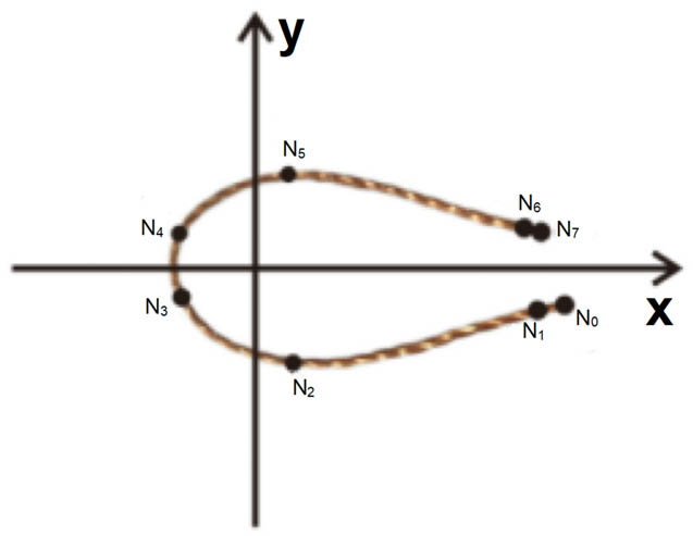
Based on the type-value points in Table 2, the loop model shown in Figure 9 is constructed.
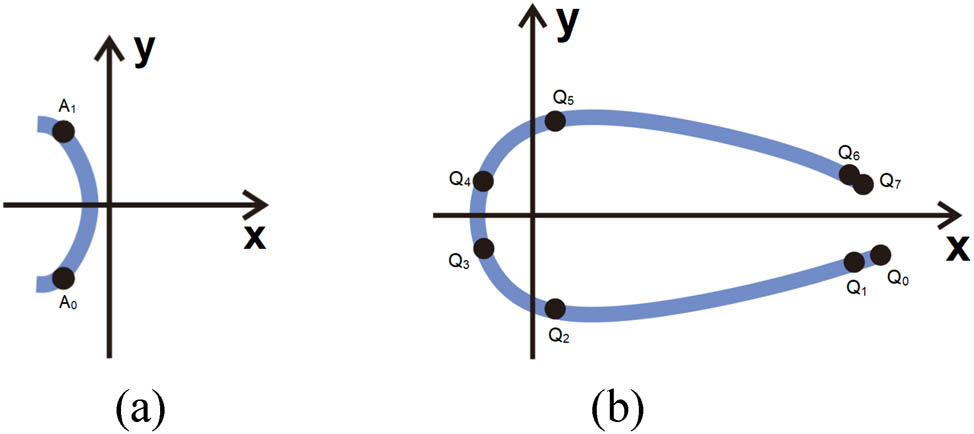
Fringe structure loop model: (a) Left-side weft insertion and (b) right-side weft insertion.
5 Design and simulation implementation
5.1 Process design
During the production of open topping-on fabric, GB1 is used to create the pillar stitch foundation, GB2 forms the looped structures, GB3 through GB5 are assigned for weft-insertion patterns, while GB6 is dedicated to fringe formation. The process is executed on a DECORTRONIC-1000-EL machine with E10 gauge (10 needles per inch), producing fabric with 5.0 wales/cm course density and 5.0 courses/cm wale density. Complete technical parameters are provided in Table 3.
Process parameters of open topping-on structured crocheted fabric
| Guided bars | Yarn specifications | Lapping numerical sequence | Threading |
|---|---|---|---|
| GB1 | A:100dtex/18F, polyester, white | 1-0/1-0/1-0/1-0/1-0/1-0/1-0/1-0// | 3A, 1*, 1A, 2*, 1A, 1*, 3A, 10* |
| GB2 | B:9900dtex/18F, polyester, espresso | 4-4/6-4/5-5/5-4/2-2/0-2/1-1/1-2// | 8*,1B,13* |
| GB3 | C:5000dtex/18F, polyester, white | 2-2/1-1/0-0/1-1/2-2/3-3/4-4/3-3// | 6*, 1C, 15* |
| GB4 | D:2500dtex/18F, polyester, red | 0-0/1-1// | 1*, 1D, 8*, 1D, 11* |
| GB5 | E:1200dtex/18F, polyester, white | 0-0/1-1// | 2*, 1E, 6*, 1E, 12* |
| GB6 | F:1200dtex/18F, polyester, russet | 0-0/12-12/0-0/14-14/0-0/14-14/0-0/16-16/0-0/16-16/0-0/18-18/0-0/18-18/0-0/20-20/0-0/20-20/0-0/22-22/0-0/22-22/0-0/22-22/0-0/22-22/0-0/20-20/0-0/20-20/0-0/18-18/0-0/18-18/0-0/16-16/0-0/16-16/0-0/14-14/0-0/14-14/0-0/12-12/0-0/14-14// | 1F, 21* |
5.2 Matrix transformation
After being taken off the machine, the open topping-on fabric is observed to undergo torsional deformations in varying directions and angles due to yarn relaxation. Based on empirical testing, the standard configuration is established as shown in Figure 10, where fringe terminals are documented to rotate around the x-axes, y-axes, and z-axes by defined angular displacements
Physical diagram of fringe terminals in standard configuration.
In simulating the torsional deformation of fabric edges, a matrix transformation algorithm based on rigid body transformation and affine transformation is employed. As shown in equation (5), first, the global coordinate system and the initial coordinates of key points on the fabric are defined, with the midpoint of the line connecting the entry and exit points of the yarn loop selected as the rotation center. Subsequently, all control points A(x,y,z)(N
1 – N
6) of the loop are uniformly translated to the local coordinate system through the transformation
where A₁ represents the matrix of control points translated to the local coordinate system, as shown in equation (6); R denotes the rotation matrix, as shown in equation (10);
The matrix A of type value points is as shown in equation (7).
The translation matrix
The translated matrix A 1 is as shown in equation (9).
Multiply the rotation matrices around different axes to obtain the combined rotation matrix R. The calculation formula of the combined rotation matrix is as shown in equation (10).
The rotation matrix
The rotation matrix
The rotation matrix
The translation matrix
The type-valued point matrix
During the computational process, the XYZ coordinate origin is positioned at the lower-left corner of the grid. The grid height is defined by j units, while the displacement along the X-axis is calculated as
This specific transformation method is chosen because it can accurately simulate the complex deformations of fabric in its natural state. In particular, when simulating the fringe structure at the fabric edge, the introduction of random rotations more realistically reflects the torsional deformation of fringes under natural conditions, thereby enhancing the realism and natural appearance of the simulation.
5.3 3D fabric simulation
Based on the aforementioned fabric structural design and loop modeling methodology, appropriate process configurations and yarn materials are selected. Through computational analysis using matrix models, the 3D structural simulation of open topping-on crochet fabric is systematically performed, with its digital model being constructed. The simulation is implemented utilizing JavaScript and C# programming languages. The workflow for the design and 3D simulation of open topping-on crochet fabric is illustrated in Figure 11.
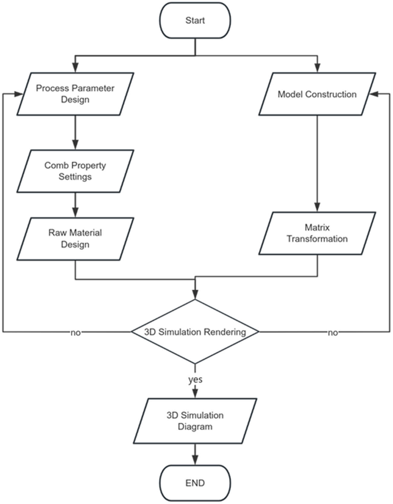
Fabric design and 3D simulation flowchart.
As shown in Figure 12, both the physical sample and simulation model of the warp-knitted open-loop fabric are presented.
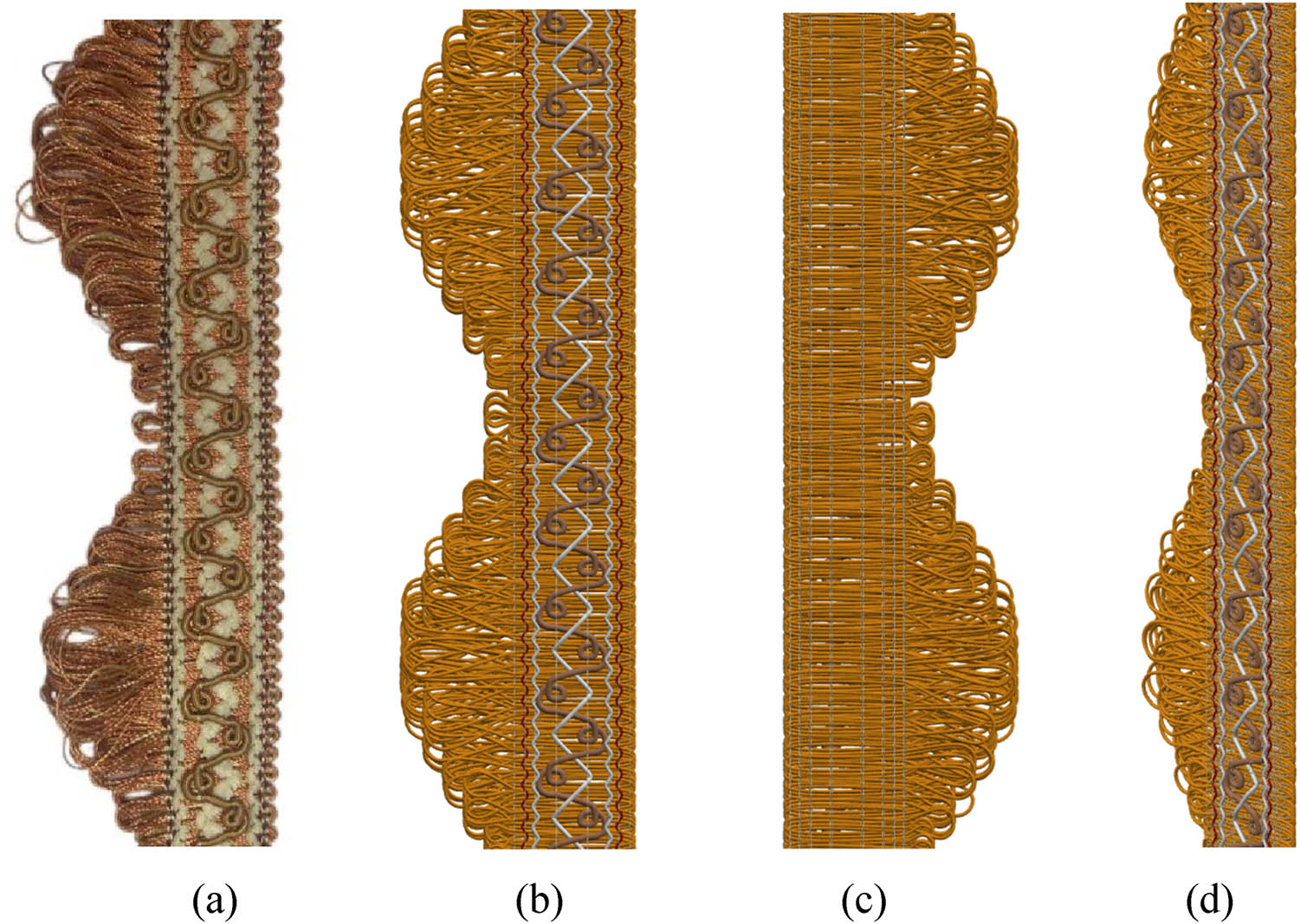
Open topping-on crochet fabric: (a) Physical photograph, (b) front of the simulation image, (c) back of the simulation drawing, and (d) side view of the simulation diagram.
Based on the above coil modeling, by modifying the process parameters, structure, yarn threading, raw materials, etc., of the fabric, diversified design and simulation of the fabric can be achieved, as shown in Figure 13.
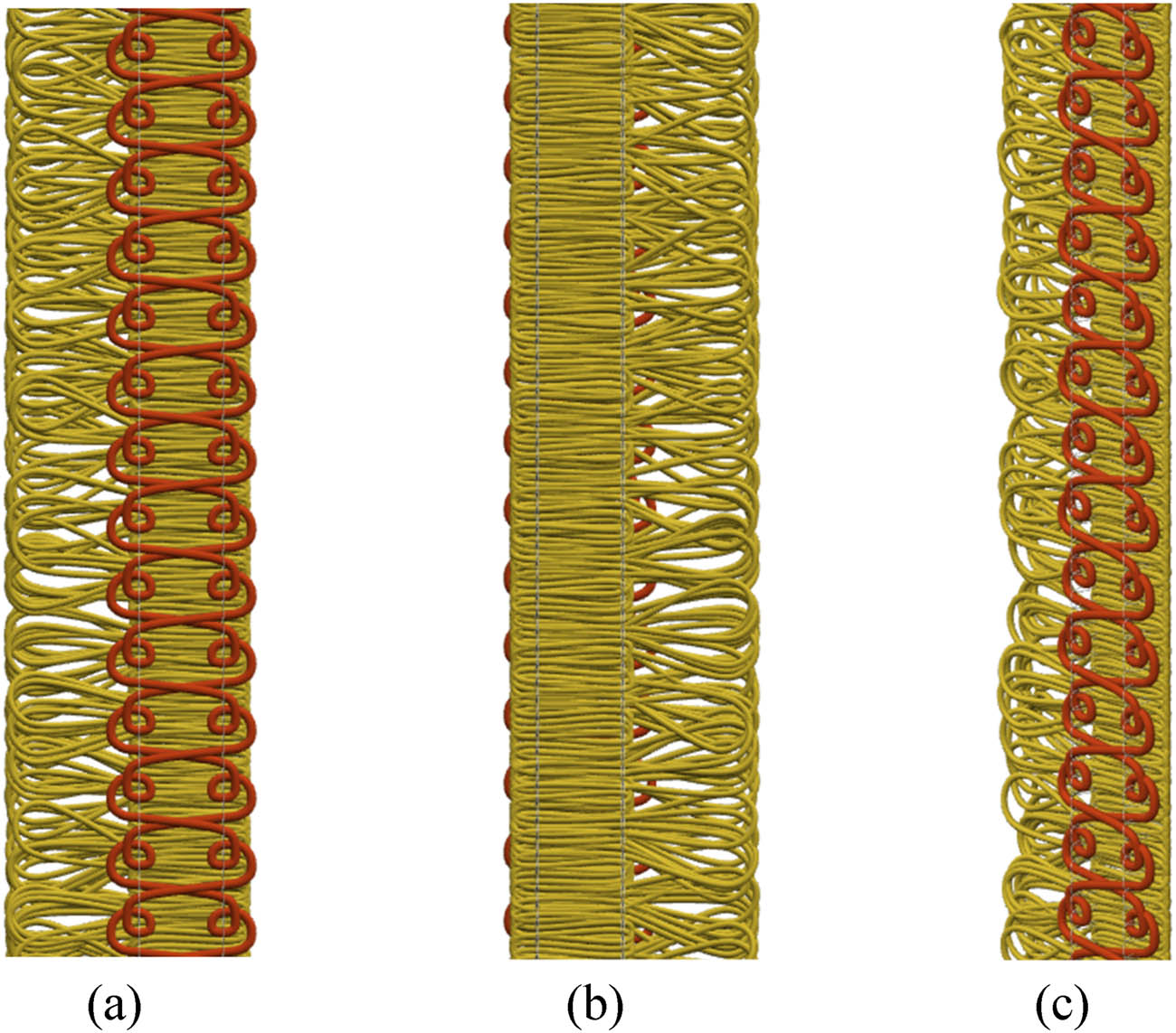
Fabric design simulation drawing: (a) Front of the simulation image, (b) back of the simulation drawing, and (c) side view of the simulation diagram.
6 Conclusion
Based on the structural characteristics of open topping-on crochet fabrics and the representation of warp-knitting lapping sequences, a mathematical model for the lapping sequence and yarn threading is constructed, enabling the drafting of process diagrams for warp-knitted open-loop fabrics. The width variations of loop encirclement are represented using needle-front lapping notations in warp knitting.
Models are developed for pillar stitch loops, standard weft-insertion loops, open-loop structures, and fringe weft-insertion loops, establishing the foundation for 3D simulation.
A composite transformation strategy combining bidirectional translation in local coordinate systems with multi-axis random rotations is implemented. This approach not only ensures unique spatial distortion patterns for each fringe terminal but also rigorously maintains topological connectivity between fringes and the main fabric structure, achieving simulated results that balance natural randomness with structural integrity.
Leveraging the established mathematical and geometric modeling framework, high-precision 3D simulation of open topping-on crochet fabric is realized through WebGL technology. Parametric loop units are constructed using the THREE.TubeGeometry component in the Three.js framework, while THREE.Mesh objects are employed to achieve topological connections and holistic fabric modeling. Experimental results demonstrate that this simulation method accurately reproduces the structural features of warp-knitted open-loop fabrics, providing reliable technical support for digital textile design.
This study conducts an in-depth analysis of the structural morphology and simulation modeling of open topping-on crochet fabrics. By employing matrix computations and programming in JavaScript and C#, a rapid design and 3D simulation methodology is proposed. If the simulation height is 100, the simulation time is within 20 s. This approach enhances new product development efficiency while significantly reducing trial-and-error costs.
Acknowledgments
The authors acknowledge the financial support from “the Wuxi Science and Technology Development Fund Project (K20241032) and the Fundamental Research Funds for the Central Universities (JUSRP202501003).”
-
Funding information: This project was support from “the Wuxi Science and Technology Development Fund Project (K20241032) and the Fundamental Research Funds for the Central Universities (JUSRP202501003).”
-
Author contributions: Buqing Sun: Mainly responsible for the construction of three-dimensional models, the implementation of simulations, and the writing of the thesis; Gaoming Jiang (Corresponding Author): Conceptualization, Funding Acquisition, Project Administration, Resources, Supervision, Writing – Review & Editing: Shukai Tang: Model-assisted construction. Haisang Liu: Essay Opinion Assistance for Revision and Guidance. Bingxian Li: Essay Opinion Assistance for Revision and Guidance.
-
Conflict of interest: Authors state no conflict of interest.
-
Data availability statement: The datasets generated during and/or analysed during the current study are available from the corresponding author on reasonable request.
References
[1] Zheng, F., Liu, Y. (2025). Yarn-level numerical simulation based on Micro-CT reconstr uction for the stentering process of warp-knitted three-dimensional mesh fabric. Textile Research Journal, 95(5–6), 615–616.10.1177/00405175241268793Search in Google Scholar
[2] Mozafary, V., Payvandy, P. (2016). Mass spring parameters identification for knitted fabric simulation based on FAST Testing and particle swarm optimization. Fibers and Polymers, 17(10), 1718–1720.10.1007/s12221-016-6567-8Search in Google Scholar
[3] Seçkin, M. (2023). FabricNET: A microscopic image dataset of woven fabrics for predicting texture and weaving parameters through machine learning. Sustainability, 15(21), 15197.10.3390/su152115197Search in Google Scholar
[4] Liu, H. S., Kyosev, Y. (2023). Realistic fabric rendering with yarn models. Textile Research Journal, 93(15–16), 2559–2563.10.1177/00405175231154534Search in Google Scholar
[5] Mao, C. D. (2007). Research on lace design in home textiles, Tianjin University of Technology, Tianjin, China.Search in Google Scholar
[6] Mao, C. D. (2019). Development of crocheting technology and trends in product development. Knitting Industry, 5, 15–17.Search in Google Scholar
[7] Mao, C. D. (2016). Research on crocheting technology for ring structure lace. Knitting Industry, 10, 14–16.Search in Google Scholar
[8] Gong, L. Y. (2014). Research on the organizational structure and simulation of crocheted knitted fabrics, Wuhan Textile University, Wuhan, China.Search in Google Scholar
[9] Shi, D. L., Mao, C. D. (2013). Study of knitting technology of crochet tassel lace knitting industry. Knitting Industry, 9, 21–23.Search in Google Scholar
[10] Mao, C. D. (2007). The design of crocheted lace fabric. Knitting Industry, 11, 21–22.Search in Google Scholar
[11] Zhou, S. (1993). CAD theory and application for warp knitted fabrics. Knitting Industry, 4, 1–8, 6.Search in Google Scholar
[12] Long, H. R. (2008). Knitting science (pp. 198–199). China Textile Publishing House, Beijing, China.Search in Google Scholar
[13] Zhang, A. J. (2018). Research on computer-aided design and simulation of warp knitted plush fabrics, Jiangnan University, Wuxi, China.Search in Google Scholar
[14] Xiong, Y., Miao, X. H., Jiang, A. J., Jiang, G. M. (2015). Computer simulation of warp-knitted pile fabric. Journal of Textile Research, 36(7), 147–151.Search in Google Scholar
[15] Zhang, L. Z., Jiang, G. M. Coil offset in 3D simulation of warp knitting structures. Journal of Textile Research, 31(3), 64–67.Search in Google Scholar
[16] Liu, H. S. (2023). Three-dimensional simulation of jacquard seamless fabric based on coil structure, Jiangnan University, Wuxi, China.Search in Google Scholar
© 2025 the author(s), published by De Gruyter
This work is licensed under the Creative Commons Attribution 4.0 International License.
Articles in the same Issue
- Study and restoration of the costume of the HuoLang (Peddler) in the Ming Dynasty of China
- Texture mapping of warp knitted shoe upper based on ARAP parameterization method
- Extraction and characterization of natural fibre from Ethiopian Typha latifolia leaf plant
- The effect of the difference in female body shapes on clothing fitting
- Structure and physical properties of BioPBS melt-blown nonwovens
- Optimized model formulation through product mix scheduling for profit maximization in the apparel industry
- Fabric pattern recognition using image processing and AHP method
- Optimal dimension design of high-temperature superconducting levitation weft insertion guideway
- Color analysis and performance optimization of 3D virtual simulation knitted fabrics
- Analyzing the effects of Covid-19 pandemic on Turkish women workers in clothing sector
- Closed-loop supply chain for recycling of waste clothing: A comparison of two different modes
- Personalized design of clothing pattern based on KE and IPSO-BP neural network
- 3D modeling of transport properties on the surface of a textronic structure produced using a physical vapor deposition process
- Optimization of particle swarm for force uniformity of personalized 3D printed insoles
- Development of auxetic shoulder straps for sport backpacks with improved thermal comfort
- Image recognition method of cashmere and wool based on SVM-RFE selection with three types of features
- Construction and analysis of yarn tension model in the process of electromagnetic weft insertion
- Influence of spacer fabric on functionality of laminates
- Design and development of a fibrous structure for the potential treatment of spinal cord injury using parametric modelling in Rhinoceros 3D®
- The effect of the process conditions and lubricant application on the quality of yarns produced by mechanical recycling of denim-like fabrics
- Textile fabrics abrasion resistance – The instrumental method for end point assessment
- CFD modeling of heat transfer through composites for protective gloves containing aerogel and Parylene C coatings supported by micro-CT and thermography
- Comparative study on the compressive performance of honeycomb structures fabricated by stereo lithography apparatus
- Effect of cyclic fastening–unfastening and interruption of current flowing through a snap fastener electrical connector on its resistance
- NIRS identification of cashmere and wool fibers based on spare representation and improved AdaBoost algorithm
- Biο-based surfactants derived frοm Mesembryanthemum crystallinum and Salsοla vermiculata: Pοtential applicatiοns in textile prοductiοn
- Predicted sewing thread consumption using neural network method based on the physical and structural parameters of knitted fabrics
- Research on user behavior of traditional Chinese medicine therapeutic smart clothing
- Effect of construction parameters on faux fur knitted fabric properties
- The use of innovative sewing machines to produce two prototypes of women’s skirts
- Numerical simulation of upper garment pieces-body under different ease allowances based on the finite element contact model
- The phenomenon of celebrity fashion Businesses and Their impact on mainstream fashion
- Marketing traditional textile dyeing in China: A dual-method approach of tie-dye using grounded theory and the Kano model
- Contamination of firefighter protective clothing by phthalates
- Sustainability and fast fashion: Understanding Turkish generation Z for developing strategy
- Digital tax systems and innovation in textile manufacturing
- Applying Ant Colony Algorithm for transport optimization in textile industry supply chain
- Innovative elastomeric yarns obtained from poly(ether-ester) staple fiber and its blends with other fibers by ring and compact spinning: Fabrication and mechanical properties
- Design and 3D simulation of open topping-on structured crochet fabric
- The impact of thermal‒moisture comfort and material properties of calf compression sleeves on individuals jogging performance
- Calculation and prediction of thread consumption in technical textile products using the neural network method