Influence of spacer fabric on functionality of laminates

Abstract
Laminates for the automotive industry are composite materials that consist of at least two layers, at least one of which has textile properties. Automotive laminates are most commonly found in vehicle interiors, including door panels, dashboards, headliners, and seats. As part of the research, the influence of three-dimensional warp knitted spacer fabrics on the functionality of laminates was investigated. The experimental part was designed in such a way that the laminates were divided into two groups. The first group comprised laminates consisting of PU foam and two layers of warp knitted fabric (Locknit), while the second group comprised laminates consisting of polyurethane foam and three-dimensional warp knitted spacer fabric. The polyurethane foam in both groups was open cell. All laminates investigated in this work were produced by flame lamination. In the experimental part, the influence of the three-dimensional warp knitted spacer fabric on the typical mechanical properties and the permeability properties of laminates for car seats was analyzed. The results show that laminates with a thickness of more than 7 mm and a proportion of the 3D warp knitted spacer fabric of 50% achieve the highest permeability, delamination force, and tensile and compressive strength.
1 Introduction
The automotive industry is constantly on the lookout for innovative solutions to improve the safety, comfort, and efficiency of vehicles. One of the most important aspects of this is the optimization of the materials used for vehicle interiors and seats. While durability, comfort, and aesthetics are important factors, the breathability of materials has also gained importance due to the growing comfort awareness of passengers [1].
Laminates used in the automotive industry are materials consisting of multiple layers of two- or three-dimensional textile or non-textile materials (PU foam, membrane, film, etc.) bonded together using various lamination techniques. The structural, physical, and mechanical properties of textile composites are very important for vehicle interiors. In addition, the permeability properties are also very important, especially for car seats. The combination of different structures in the laminated textiles using three main lamination techniques, such as dry, wet, and flame lamination, influences the mechanical and permeability properties [2].
The lamination process and the structural properties of the laminate influence its mechanical properties such as strength, elongation, and elasticity. On the other hand, they also influence the permeability properties of the laminate. The mechanical properties and permeability properties of laminates used for car seats are important from a practical point of view. The requirements for such laminates are that they withstand tensile and compressive loads, retain their elastic properties during use, they are abrasion-resistant, and have optimum rigidity. On the other hand, permeability properties such as air permeability, water vapor permeability, and thermal conductivity are important. Laminates for car seats must ensure the passage of air and water vapor. This ensures the comfort of the user, prevents the spread of unpleasant odors, and the condensation of water vapor on the surface of the laminate. On the other hand, thermal conductivity and air permeability are important for car seats that have built-in heating for the passenger. Therefore, such laminates must also have adequate thermal conductivity [3].
Understanding the influence of the structure of 2D and 3D textiles on the strength and permeability properties of the laminate is very important with regard to the combination of 2D and 3D textiles with polyurethane foam, which is most common in such laminates produced by flame lamination [2].
The aim of the research was to find out how the three-dimensional (“spacer”) knitted fabrics affect the strength and permeability of the entire laminate, whether positively or negatively. A positive effect means an increase in strength and permeability.
Some researchers have investigated the influence of spacer fabrics on the air permeability of laminates [4]. In the study, the authors found that spacer fabrics are a highly breathable and moisture-free material that provides higher comfort compared to PU foam, which is also very important for laminates used for car seats. The research results show that knitted spacer fabrics have a higher air trapping capacity and a double-sided nature, leading to their extensive use in the automotive industry in general. The research results also show that spacer fabrics have excellent damping performance and pressure distribution due to the sandwich structure [4]. Previous studies have shown that the pressure properties are significantly affected by spacer fabrics in the bonding layer, i.e., they retain the shape of the car seat cover when used [4].
Arumugam et al. investigated the heat and water vapor permeability of porous knitted 3D spacer fabrics for car seat covers [5]. They found that the raw materials, the type of spacer yarn, the density, the thickness, and the tightness of the surface layer have a significant influence on the permeability of spacer knitted fabrics. The parameters that mainly influence the water vapor permeability of these fabrics are porosity, density, and thickness [5].
Arumugam et al. presented the study of thermophysiological properties of 3D spacer fabrics for car seats [6]. The research results show that spacer fabrics with hexagonal mesh structure have a more open structure on the surface than lock-knitted fabrics, resulting in high air permeability with good thermal conductivity [6].
Datta et al. investigated the compression behavior of warp-knitted spacer fabrics with a cylindrical surface [7]. The research results show that flat compression and cylindrical compression are largely shifted in terms of load-deformation curve shape and compression energy. It was also found that the thickness of the spacer fabric and the fineness of the yarn have an influence on the compression behavior [7].
Song et al. also investigated the compression behavior of warp-knitted spacer fabrics using the simplified finite element method [8]. They found that warp-knitted spacer fabrics have excellent compression properties. Using the finite element method, they successfully simulated the compression process of spacer fabrics and found that the simulated results closely matched the experimental results in terms of the compression force–strain and compression work–strain curves [8].
Chan et al. investigated textile–silicone composites and automotive interior for car seats [9]. The research focuses on the influence of composite structure and thickness on the mechanical and thermal properties of textile–silicone materials. The results show that an additional knitted powernet fabric as a composite material can improve the tensile properties of silicone rubber by up to 315%. They found that the textile composites without perforation had significantly lower water vapor permeability than the spacer sample in terms of structure, thickness, and weave. The knitted meshes of the fabric layers allow water vapor to pass through and prevent moisture from being trapped.
Li et al. investigates the mechanical and thermal behavior of knitted spacer fabrics with insoles for insoles [10].
The results show that the density of the insole and the spacer thread increase the compressive strength and reduce the impact forces. A higher density of the spacer thread provides better air permeability but decreases thermal resistance, while a lower density of the randomly oriented insole decreases evaporative resistance [10].
Compared to polyurethane foam, textile car seat covers are easier to recycle; textile car seat covers are a good candidate to replace foam covers as recycling regulations for car manufacturers have become stricter. The results show that knitted spacer fabrics have better compression strength, thermal properties and breathability compared to polyurethane foam [11].
1.1 Presentation of laminates for the automotive industry
A textile laminate is a material consisting of two or more layers, where at least one layer is a textile and at least one layer is a pure polymer layer. The layers are firmly bonded together by an additional binder in the form of hard powder, paste, foam, fibers or thermoplastic films, and fabrics [11]. Laminates belong to the group of technical textiles, where the focus is on technical rather than esthetic properties [12].
The main purpose of laminates is to increase wear resistance and improve or maintain certain properties compared to single layers as a base material for lamination [3,11].
There are many different techniques and binders to choose from for the lamination process. When using a binder, it is important that delamination does not occur and that the material retains its original properties after lamination, while ensuring flexibility by achieving the desired appearance and durability [3,11,13].
The most important functional properties of laminates are good wrinkle resistance, good insulating properties with low weight and good dimensional stability [11,12].
They are used in various industries, from the security and leisure industry to the automotive industry and the clothing and decoration industry.
At the end of a laminate’s life cycle, the question of recycling such a material arises for many people. Material recycling is a very important part of the life cycle of an item. Life cycle assessment (LCA) is a method of analyzing the environmental impact of a product at all stages of its life cycle, covering the entire chain from the sourcing of raw materials to the end of its useful life [14].
The analysis includes an overview of all environmental impacts at all stages of the cycle, i.e., consumption of resources, water and energy, and emissions (CO2 and other emissions of hazardous substances, if they occur). The phases of the cycle follow the sequence from the procurement of raw materials, through the manufacture of the material, production, distribution, and use, to what happens to the material after its useful life [15,16].
The LCA methodology is therefore fundamental for answering the question of which circular economy strategy provides the greatest environmental benefit [15,16].
Laminate is not recyclable in most cases as the layers cannot be easily separated and recycled. However, it can be shredded into smaller pieces and then recycled layer by layer or depending on the composition of the raw material. Each layer is then recycled into a new product [17,18,19].
1.2 Presentation of materials for laminates
1.2.1 Polyurethane foam
Polyurethane foam is a thermoplastic material with a porous structure. It is characterized by its versatility. It has a wide range of applications in engineering, as it is a stable and durable material that is resistant to corrosion, does not change its structure and has good resistance to oils and chemicals [19,20,21,22].
Polyurethane foam has a wide range of density, stiffness, and hardness, which is determined by its chemical composition. It is characterized by its elasticity, good thermal insulation and sound absorption, resistance to temperature fluctuations, corrosion, moisture, and mold [22].
Polyurethane foams are made from three main components: Polyols, diisocyanates, and additives that provide a balanced and accelerated reaction. The basic additives that are added to polyurethane foams are as follows: Foaming agents, surfactants, catalysts, and crosslinking agents (crosslinkers and chain extenders) [23].
The foaming agent is used to generate gas during the production of the cell structure of the foam. It is introduced by chemical or physical means. Surfactants stabilize the reaction by reducing the interfacial tension. Catalysts are used to control the reaction rate and the rate of gas formation. The speed and duration of the two reactions must be balanced in order to produce uniform open cells. Auxiliaries include crosslinkers and chain extenders that contribute to the formation of stable chains or networks [19,20,21,22,23].
In addition to the basic additives, we add other additives that change the properties of the foam in favor of certain mechanical properties. We know of additives that make it possible to subsequently process the foam with a flame or hot-melt binder, foams with low emissions, foams with high compressive strength, solid, air-permeable, barrier, memory foams, etc. [19,20,21,22,23].
After production, the foam is poured into a block, which is cut to a specific thickness after solidification. Polyurethane foams are classified into closed-cell or ordinary and open-cell.
The greatest demand for laminates is in the automotive industry for seats. Most of these are PU foams, which have disadvantages in terms of comfort and recycling. The solution to these shortcomings is a three-dimensional mesh, which has higher compressive strength, air permeability, and better thermal conductivity than foam.
1.2.2 Spacer fabrics
3D warp knitted fabrics (spacer fabrics) are characterized by two outer layers that are connected by spacer threads and form a sandwich-like arrangement. In warp knitting, each needle stitch has its own thread, creating a fabric of interlocking stitches in a vertical direction. Warp-knitted spacer fabrics are produced on Raschel machines with double needle bars, which enable complex structures and the integration of spacer threads [24,25].
The top and bottom can be knitted in the same way to create an open structure, but the bottom can be knitted more densely to create a closed structure. The open structure provides good structural stability and good air permeability, and a mesh structure is used to achieve high air permeability.
In the intermediate layer, monofilament threads connect the top and bottom layers of the fabric. The type of monofilament yarn used determines the properties, compressibility, elasticity, drape, absorbency, and insulating properties as well as the wearing comfort [26,27,28].
2 Experimental method
2.1 Materials
The laminate samples examined in the study were divided into two groups: Group 1 (samples 1.1, 1.2, 1.3) and Group 2 (samples 2.1, 2.2, 2.3). In Group 1, the laminate samples consisted of polyurethane foam and two warp knitted fabrics (Locknit). The samples in Group 1 were produced using the flame lamination process. In this process, the polyurethane foam is softened on the front and back with a flame on the surface and then laminated with a laminating roller on the front and back with two warp knitted fabrics (Locknit). The resulting laminate contains a polyurethane foam in the middle and a two-lane guide bar warp-knitted fabric (Locknit) on the front and back. The total thickness of these samples was 3, 5, and 10 mm (Tables 1 and 2).
Physical properties of the individual laminate components
| Sample | Component 1 (PU foam) | Component 2 (knitted fabric) | Component 3 (knitted fabric) | Total | |||||
|---|---|---|---|---|---|---|---|---|---|
| Thickness (mm) | Density (kg/m3) | Type of knitted fabric | Thickness (mm) | Mass (g/m2) | 2D/3D knitted fabric | Thickness (mm) | Mass (g/m2) | Thickness (mm) | |
| 1.1 | 2.5 | 52 | 2D | 0.2 | 36 | 2D | 0.2 | 36 | 2.91 |
| 1.2 | 4.5 | 46 | 2D | 0.2 | 36 | 2D | 0.2 | 36 | 4.88 |
| 1.3 | 8.9 | 45 | 2D | 0.2 | 36 | 2D | 0.2 | 36 | 9.40 |
| 2.1 | 6.1 | 43 | 3D | 3.4 | 214 | — | — | — | 8.98 |
| 2.2 | 3.9 | 44 | 3D | 3.7 | 257 | — | — | — | 7.64 |
| 2.3 | 3.9 | 44 | 3D | 6.1 | 388 | — | — | — | 9.74 |
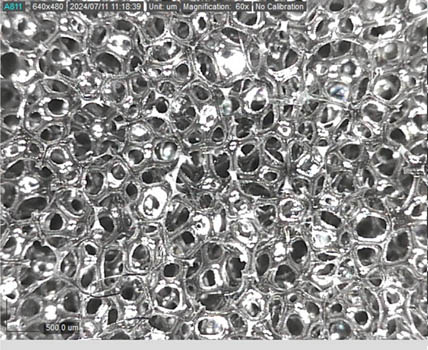
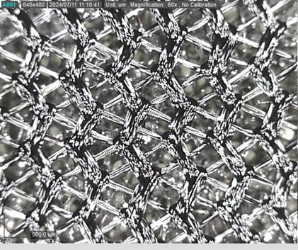
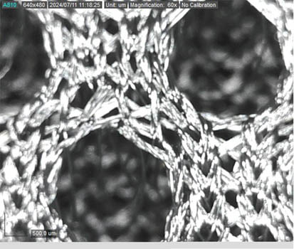
Microscopic view of the components used in the laminate samples (50× magnification)
| Samples | Component 1 (PU foam) | Component 2 (knitted fabric) | Component 3 (knitted fabric) | Cross-section view |
|---|---|---|---|---|
| 1.1, 1.2, 1.3 |
 |
 |
 |
 |
| 2.1, 2.2, 2.3 |
 |
 |
— |
 |
Group 2 comprised laminates consisting of polyurethane foam and a layer of 3D warp-knitted fabric (spacer fabric). The polyurethane foam is softened only on the reverse side with a flame and then laminated with a 3D warp knitted fabric (spacer fabric) using a laminating roller. The resulting laminate contains polyurethane foam on the back and a spacer fabric on the front. Group 2 samples differ in the proportion of 3D warp knitted fabric (spacer fabric) in the laminate. Their total thickness is between 8 and 10 mm. All six samples were produced using the flame laminating process with a double burner flame laminating machine. For all tests, a total laminate length of 5 m was required for the two sample groups, with a roll width of 1.2 m.
The present study focuses on the comparison between the laminates of Groups 2 and 1. The influence of the 3D warp knitted fabric (spacer fabric) on some mechanical and permeability properties of the produced laminate was investigated. The laminate samples of Group 2 consist of 40, 50, and 60% 3D warp knitted spacer fabrics, based on the thickness of the entire laminate sample. Sample 2.1 consists of 40% 3D spacer knitted fabric and 60% PU foam, sample 2.2 consists of 50% 3D warp knitted spacer fabric and PU foam, and sample 2.3 consists of 60% 3D warp knitted spacer fabric and 40% PU foam. The warp knitted spacer fabrics were produced on a double-needle bar knitting machine with six guide bars. In double-needle bar knitting, two layers of fabric are knitted simultaneously and spacer threads are inserted between them.
The compositions of the laminate samples are listed in Table 1. The microscopic examination of the individual components of the laminate is shown in Table 2. The cross-sectional images of the two groups of samples are shown in Figure 1. The structural properties of the 2D warp knitted fabrics (Locknit fabrics) and 3D warp knitted fabrics (spacer fabrics) are listed in Table 3.
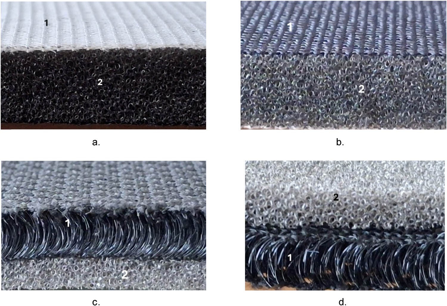
The cross-sectional images of the samples: (a and b) samples 1.1, 1.2, and 1.3 on the front and back: 1 – Locknit fabric and 2 – PU foam; (c and d) samples 2.1, 2.2, and 2.3. on the front and back: 1 – warp knitted spacer fabric and 2 – PU foam.
Structural properties of 2D and 3D warp knitted spacer fabrics in laminates
| Sample | Construction of knitted fabric | Type of knitted fabric | Component 2 (knitted fabric) | Fabric | Component 3 (knitted fabric) | ||
|---|---|---|---|---|---|---|---|
| Density (cm−1) | Density (cm−1) | ||||||
| Wales | Courses | Wales | Courses | ||||
| 1.1 | Locknit fabric | 2D | 12 | 14 | Locknit fabric | 12 | 16 |
| 1.2 | Locknit fabric | 2D | 12 | 14 | Locknit fabric | 12 | 16 |
| 1.3 | Locknit fabric | 2D | 12 | 14 | Locknit fabric | 12 | 16 |
| 2.1 | Warp knitted spacer fabric | 3D | 16 | 20 | — | — | — |
| 2.2 | Warp knitted spacer fabric | 3D | 16 | 20 | — | — | — |
| 2.3 | Warp knitted spacer fabric | 3D | 16 | 20 | — | — | — |
2.2 Methods
2.2.1 Thickness
The thickness of the samples was measured by preparing five parallel samples according to the ISO 5084 standard [29]. The results were expressed in millimeters (mm).
2.2.2 Mass
The mass was determined in accordance with ISO standard 3801 [30]. Five measurements were carried out for each sample. The results obtained were expressed in g/m2.
2.2.3 Air permeability
Air permeability is the amount of air that can pass through a given surface in a given time and under a given pressure. Air permeability was measured in accordance with the ISO 9237 standard [31] using the Air-Tronic B device (Mesdan, Raffa, Italy), which measures the volume of air in m3 that passes through an area of 1 m2/min. The measurements were carried out on a measuring surface of 20 cm2 and at a pressure of 200 Pa. Five measurements were taken on each sample. The air permeability was given in m3/m2 min.
2.2.4 Water vapor permeability
The water vapor permeability was measured by adding 7 mL of water to a beaker and placing a lid with a diameter of 3 cm and a lid with an opening of 3 cm in diameter on top. The entire setup was weighed and then placed in the chamber for 24 h. It was then weighed again, and the percentage of evaporated water was noted. The measuring conditions in the chamber were 22°C and a humidity of 65%. Five measurements were carried out on each sample. The water vapor permeability measurements were performed according to ASTM E96/E96M [32] and expressed in g/m2 h.
2.2.5 Breaking force and elongation
The breaking force and elongation were measured on the dynamometer. The 5 cm × 15 cm samples were cut five times in parallel in the longitudinal direction (MD) and in the transverse direction (CD). The clamping length on the dynamometer was 10 cm. The breaking force and elongation were measured according to ISO 13934-1 [33]. Five measurements were carried out on each sample in the MD and CD directions. Breaking stress and elongation were measured on the Instron 5567 dynamometer (Instron, Bristol, UK).
2.2.6 Strength under load with a ball
The strength under ball compression loading was measured on the dynamometer. A ball with a diameter of 40 mm and an attachment with an opening diameter of 45 mm were used. Before starting the measurement, the ball was moved to the point of contact with the sample, which was the starting point of the measurement (point zero). The sample was loaded until it broke. At break, the deformation of the sample was recorded in mm. The deformation of the sample is measured from the point of contact of the sample with the ball (point zero) until breakage and is given in millimeters. Five measurements were performed on each sample. The result is the deformation in mm and the breaking force under compressive load in N. The measurements were carried out in accordance with the ISO 13938-2 standard [34]. The strength under load with a ball was measured on the Instron 5567 dynamometer (Instron, Bristol, UK).
2.2.7 Stratification force
The stratification force was measured on the Instron 5567 dynamometer (Instron, Bristol, UK) with part of the layered knitted fabric clamped in the upper holder and the lower part of the layered PU foam. The result is the force required to layer the PU foam over a width of 5 cm. Five measurements were carried out on each sample in the MD and CD directions. The stratification force was determined in accordance with ISO 2411 [35].
2.2.8 Statistical analysis
A one-way ANOVA was performed to determine the significance of the spacer fabric added to the PU foam in the laminate for the permeability properties (air permeability, water vapor permeability) and the mechanical properties (breaking force and elongation, strength under load with a ball, stratification force).
If the p-value is greater than 0.05 (i.e., p > 0.05 or p > 5%), the null hypothesis is accepted, which means that the differences between the classes are random. If the p-value is 0.05 or less, the result is considered significant and the null hypothesis is rejected, meaning that there are differences between the classes and that these differences are statistically significant.
The ANOVA was performed with the statistical software SPSS version: 29.0.0.0 (241) (IBM, London, UK) [36].
3 Results and discussion
In this section, the results are presented with a discussion of important physical parameters, such as thickness and mass of the laminates of the first and second groups. In the following section, the results are presented with a discussion of the permeability properties, such as air permeability and water vapor permeability. Sections 3.7 and 3.8 presents the mechanical properties, such as tensile and compressive strength and the force required for delamination.
The results of the significance of the influence of the individual layers, in our case the 3D warp knitted spacer fabric, on the permeability and the mechanical properties are presented using ANOVA in Section 3.9.
3.1 Thickness
The samples of Group 1 are 2.91, 4.88, and 9.40 mm thick. Their structure is the same, only the thickness of the polyurethane foam changes. The samples of Group 2 are 8.98, 7.64, and 9.74 mm thick. The proportion of the 3D warp knitted spacer fabric and the proportion and thickness of the PU foam have changed. The results of the sample thickness measurements are summarized in Table 4.
Results of measurements of laminate thicknesses
| Sample | PU foam thickness (mm) | Thickness 2D/3D-knitted fabric (mm) | Laminate thickness (mm) | |||||||
|---|---|---|---|---|---|---|---|---|---|---|
| Average (mm) |
|
CV (%) | No. of plies | Average (mm) |
|
CV (%) | Average (mm) |
|
CV (%) | |
| 1.1 | 2.46 | 0.06 | 2.31 | 2 | 0.25 | 0.00 | 1.77 | 2.91 | 0.04 | 1.37 |
| 1.2 | 4.51 | 0.06 | 1.28 | 2 | 0.25 | 0.00 | 1.77 | 4.88 | 0.04 | 0.87 |
| 1.3 | 8.88 | 0.06 | 0.67 | 2 | 0.25 | 0.00 | 1.77 | 9.40 | 0.05 | 0.53 |
| 2.1 | 6.07 | 0.03 | 0.53 | 1 | 3.48 | 0.15 | 4.33 | 8.98 | 0.05 | 0.56 |
| 2.2 | 3.93 | 0.02 | 0.58 | 1 | 3.74 | 0.20 | 5.26 | 7.64 | 0.05 | 0.60 |
| 2.3 | 3.93 | 0.02 | 0.58 | 1 | 6.10 | 0.07 | 1.14 | 9.74 | 0.05 | 0.53 |
The thickness of the sample depends on the thicknesses of the individual components [1]. The sum of the thicknesses of the individual components is greater than the final thickness of the laminate (Table 4). Only for sample 2.1 was the measured total thickness of the sample about 0.5 mm less than the sum of the individual thicknesses of PU foam and 3D warp knitted spacer fabric. The reason for this is most likely due to the flame lamination process, where the softening of the foam during flame lamination led to a greater change in the thickness of the PU foam, which most likely had an effect on the lower overall thickness of sample 2.1. It was assumed that the thickness of the PU foam decreased during the flame lamination of sample 2.1, while the thickness of the 2D locknit and 3D warp knitted spacer fabric did not change (Table 4).
A more detailed sum of the thicknesses of the individual components and the total thickness of the samples are shown in Table 4. It can be concluded from Table 4 that the flame lamination has only a minor influence on the change in thickness of the laminate sample.
3.2 Mass
The results of the masses of the samples analyzed are summarized in Table 5.
Mass of components and laminates
| Mass (g/m2) | ||||||||||
|---|---|---|---|---|---|---|---|---|---|---|
| Sample | PU-foam | Knitted fabric 2D/3D | Laminate | |||||||
|
|
|
CV (%) | Knitted fabric |
|
|
CV (%) |
|
|
CV (%) | |
| 1.1 | 127.60 | 2.19 | 1.72 | 2D | 44.80 | 0.84 | 1.87 | 234.00 | 0.01 | 0.01 |
| 1.2 | 208.00 | 2.12 | 1.02 | 2D | 44.80 | 0.84 | 1.87 | 309.00 | 0.02 | 0.01 |
| 1.3 | 396.20 | 1.92 | 0.49 | 2D | 44.80 | 0.84 | 1.87 | 499.00 | 0.01 | 0.00 |
| 2.1 | 262.40 | 3.13 | 1.19 | 3D | 213.80 | 6.10 | 2.85 | 476.00 | 5.66 | 1.19 |
| 2.2 | 169.60 | 2.07 | 1.22 | 3D | 257.20 | 2.39 | 0.93 | 427.00 | 4.67 | 1.09 |
| 2.3 | 169.60 | 2.07 | 1.22 | 3D | 388.40 | 5.13 | 1.32 | 577.00 | 6.88 | 1.19 |
Table 5 shows that the 3D warp knitted spacer fabrics have a considerable influence on the total mass of the sample. For samples 2.2 and 2.3, foam with the same thickness and mass was used, onto which various 3D warp knitted spacer fabrics with different masses were laminated (Table 5).
The 3D warp knitted spacer fabrics of samples 2.2 and 2.3 with a higher proportion of 3D warp knitted spacer fabrics have a greater mass than the foam with a comparable thickness (refer Section 2.1). Table 4 shows that the 3D warp knitted spacer fabrics of sample 2.2 (thickness 3.74 mm) with a mass of 257.20 g/m2 and the foam of this sample (thickness 3.93 mm) with a mass of 169.6 g/m2 or the 3D warp knitted spacer fabrics of sample 2.3 (thickness 3.48 mm) with a mass of 388.4 g/m2 and the foam of sample 2.3 (thickness 3.93 mm) with a mass of 169.9 g/m2 can be compared with each other. In both comparisons, the surface mass of the 3D warp knitted spacer fabric is greater than the mass of the foam (Table 5).
3.3 Air permeability
The air permeability measurements of all six samples are shown in Figure 2, where the samples are shown with increasing thickness.

Air permeability of samples.
The samples in Group 1 are lighter colored in the graph than the samples in Group 2. Figure 3 shows that the thickness of the sample affects the air permeability because, as previously mentioned, air permeability decreases with increasing thickness and mass [4]. The decrease in air permeability is greater in Group 1 than in Group 2, where the thickness range is smaller (Figure 2).
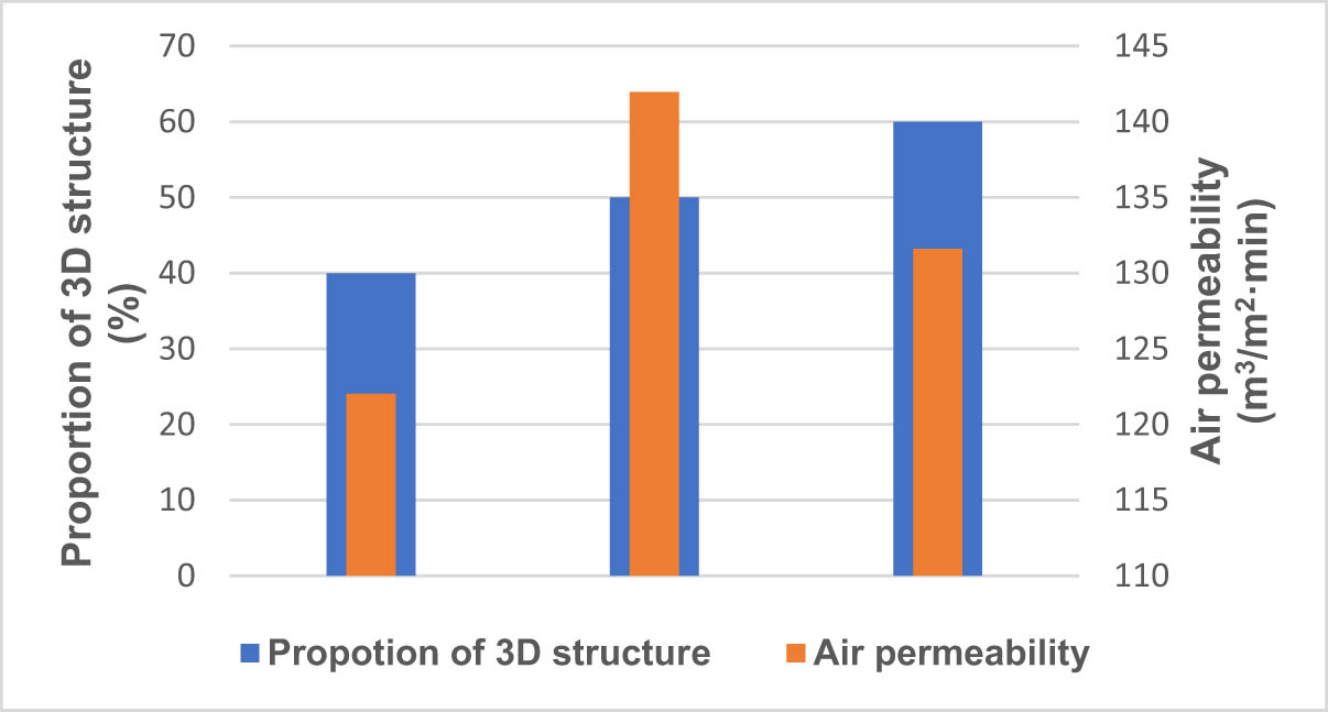
Proportion of 3D warp knitted spacer fabric and air permeability of samples.
The measurements on the samples in group 1 (samples 1.1, 1.2, and 1.3) show a decrease in air permeability with increasing thickness. These samples have the same composition, only the foam is of different thickness (Table 4). Their results are shown in Figure 2, which shows that the difference in air permeability is very small for thicknesses of 3 and 5 mm, while it decreases sharply for samples thicker than 5 mm. PU foam thicker than 5 mm offers greater resistance to air flow through the structure, although the density of the PU foam is slightly lower (45 kg/m3, Table 1). PU foam with a thickness of more than 5 mm has 33% less air permeability than PU foam with a thickness of 4.5 mm (sample 1.2).
Comparing a sample of Group 1 with Group 2 (Table 4), it can be seen that the measurements of group 2 have a smaller thickness variation (from 7.64 to 9.74 mm), while the air permeability values vary between 122 and 141 m3/m2 min (Figure 2). These samples have different thicknesses of PU foams and different thicknesses and masses of 3D warp knitted spacer fabrics, thickness of 9.40 mm for a sample 1.3 of Group 1 with a thickness of 9.74 mm (sample 2.3), the samples of Group 2 with the 3D warp knitted spacer fabric have a higher air permeability despite the greater thickness. At a thickness of more than 9 mm, the 3D structure has a positive influence on the air permeability of the samples.
From the results, it can be concluded that the use of a 3D warp knitted spacer fabric is effective with a sample thickness of 8 mm and thicker. Samples with a thickness of less than 8 mm do not require a 3D warp knitted spacer fabric to achieve high air permeability values, as the polyurethane foam takes over this task.
Samples 2.1, 2.2, and 2.3 have 3D warp knitted spacer fabric proportions of 40, 50, and 60% in relation to the thickness of the total sample (Section 2.1).
Figure 3 shows samples with increasing proportions of 3D warp knitted spacer fabric (40, 50, 60%). When changing from 40 to 50% of the 3D structure, the air permeability increased. This decreased with an increase in a further 10–60%. With flame lamination, where a single layer of PU foam and 3D fabric makes up 50% of the total thickness of the laminate, we also achieve the lowest thickness of the laminate, and consequently, this method also has the highest air permeability of such a laminate: In our case, it is sample 2.2 with a thickness of 7.64 mm, the thickness of samples 2.1, which contains 40% 3D warp knitted spacer fabric, and 2.3, which contains 60% 3D warp knitted spacer fabric, is on average 2 mm thicker. For this reason, the air permeability is also about 14% lower. For our samples, the most ideal composition is 50% polyurethane foam and 50% 3D warp knitted spacer fabric.
3.4 Water vapor permeability
Figure 4 shows that the water vapor permeability of samples 1.1, 1.2, and 1.3 also increases with increasing thickness. For samples 2.1, 2.2, and 2.3, sample 2.1 with 40% 3D warp knitted spacer fabric has the highest value, followed by sample 2.3 with 60% 3D structure and then sample 2.2 with 50% 3D structure, which has the lowest thickness among the samples in the second group. The sample with a lower proportion of 3D warp knitted spacer fabric than foam has better water vapor permeability, which is particularly evident when comparing sample 2.3 with sample 1.3, which have a difference in thickness of only 0.34 mm (Figure 4 and Table 4).

Water vapor permeability of samples.
In the results for air permeability of samples 1.1, 1.2, and 1.3, the value of air permeability decreased with increasing thickness, while the opposite was true for the results for water vapor permeability: the values increased as the thickness of the sample increased, resulting in sample 1.3 having better water vapor permeability than samples 1.2 and 1.1. The value of water vapor permeability is inversely proportional to air permeability [4].
The results of the water vapor permeability showed that with a larger proportion of PU foam in the laminate, the proportion of open spaces and thus a larger number of pores also increases, which allows a greater passage of water vapor through the sample into the atmosphere over 24 h [5]. This was already evident in the samples of the first group, where the water vapor permeability increased with increasing thickness of the PU foam. The same applies to the samples in the second group: the water vapor permeability decreases as the proportion of PU foam decreases and the proportion of 3D warp knitted spacer fabric increases.
The results show that the value of water vapor permeability decreases by about 15% when we increase the proportion of 3D structure to 50%. This means that 3D warp knitted spacer fabrics significantly reduce the water vapor permeability when they make up 40–50% of the total thickness of the laminate. The opposite was found for the proportion of 3D warp knitted spacer fabrics of 60% of the total thickness, as in this case, the water vapor permeability increased again by about 12%.
3.5 Breaking force
The breaking force represents the force at which the specimen breaks or the durability of the material in the unit N/cm [15]. The results of the tensile forces of the samples in the longitudinal and transverse directions are shown in Figure 5.
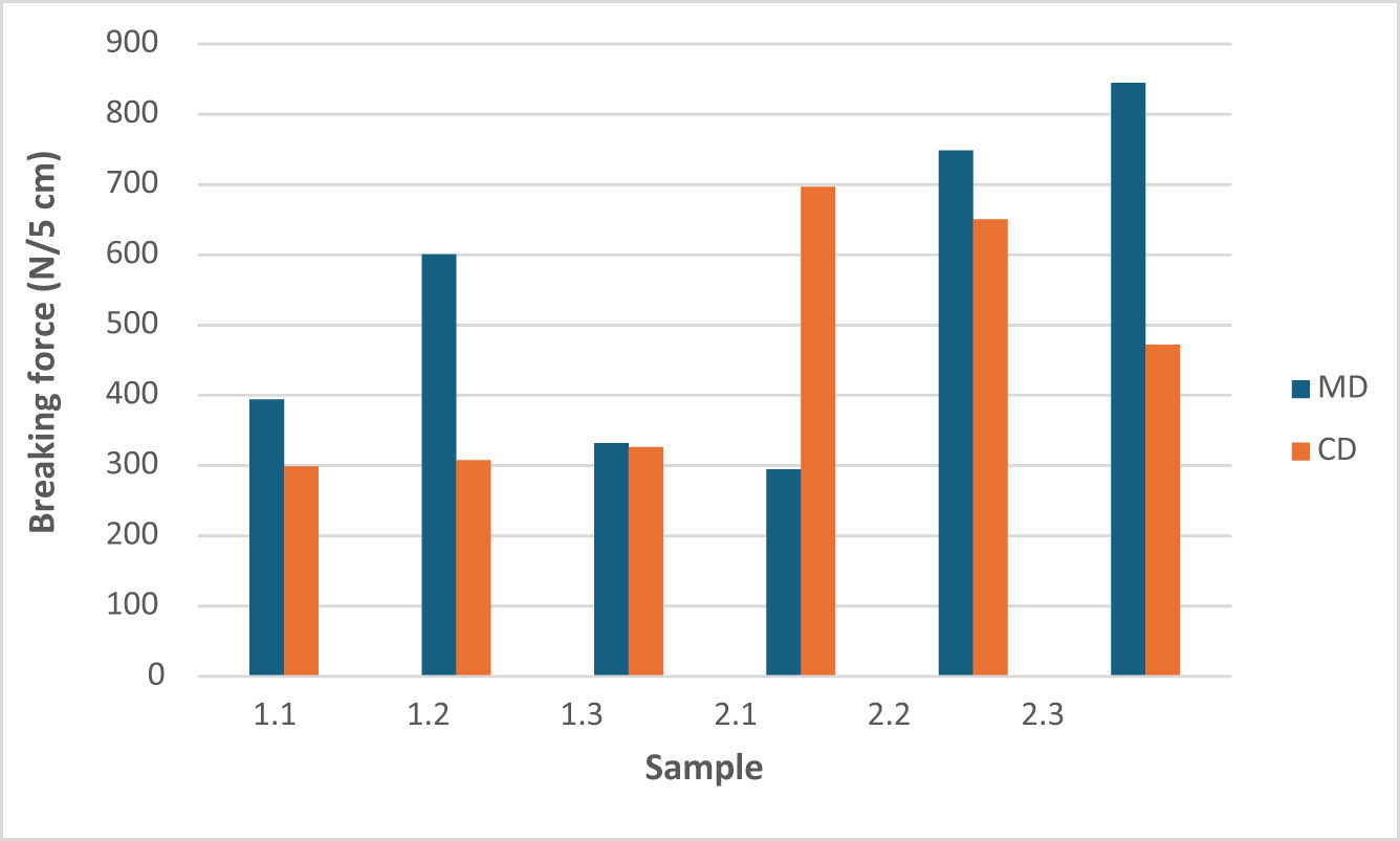
Breaking force of samples; MD – machine direction and CD – cross direction.
In the samples of the first group with an increase in thickness from 3 to 5 mm, the breaking strength almost doubles with increasing thickness and the density of the foam decreases from 52 to 46 kg/m3, which means that the foam increases the strength and reduces the elongation at break. When the thickness is further increased from 5 to 10 mm, the opposite effect occurs, as the breaking force decreases by almost half due to the almost doubled thickness at a similar foam density (45 kg/m3) as the foam in sample 1.2.
For the samples in Group 2, the breaking force increases with an increasing proportion of 3D warp knitted spacer fabrics. Samples 2.2 and 2.3 exhibit a maximum breaking force, i.e., these two samples would withstand maximum loads. Compared to sample 2.1, they have a higher overall thickness and a higher thickness of the three-dimensional structure, which gives them greater flexibility and consequently higher strength.
From the measurements, it can be concluded that samples with a 3D warp knitted spacer fabric have higher breaking forces and are more durable.
The samples were also measured with a breaking force in the CD direction or in the transverse direction. All samples, with the exception of sample 2.1, show lower values for the CD breaking force than the MDs. The measurement results are summarized in Figure 5.
In Figure 5, the forces required to break the sample in the longitudinal direction (MD direction) are colored blue and the forces in the transverse direction (CD direction) are colored orange. Specimen 2.3 has the highest breaking force in the longitudinal direction and specimen 2.1 in the transverse direction.
Of all the samples, sample 2.2 would perform best, as it has higher values in both the MD and CD directions. Samples 1.1, 1.2, and 1.3 have a lower breaking force as they contain more foam, which has a lower breaking force than three-dimensional knitted fabric.
3.6 Stratification force
The results of stratification forces in the longitudinal (MD) and in the transverse (CD) directions are summarized in Figure 6.
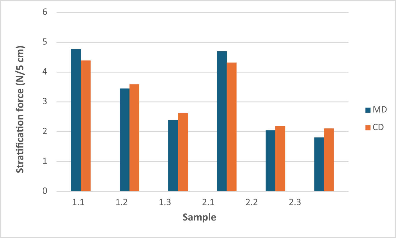
Stratification force of samples; MD – machine direction and CD – cross direction.
Figure 6 shows that for samples 1.1, 1.2, and 1.3, the stratification force decreases with increasing thickness, which means that the surface of thinner PU foams is softer during flame lamination and has greater adhesion, resulting in higher stratification force values than for thicker PU foams [1,9,10]. The greater the adhesion, the greater the stratification force. For samples 2.1, 2.2, and 2.3, the stratification force decreases when the proportion of 3D warp knitted spacer fabric is increased. Samples with a lower proportion of 3D structure have better adhesion to the PU foam, which leads to higher stratification forces.
The stratification forces in the transverse direction (CD) are similar to those in the longitudinal direction (MD). In the transverse direction (CD) as in the longitudinal direction (MD), the stratification force decreases with increasing sample thickness in Group 1. Similarly, the stratification force decreases with increasing proportion of the 3D warp knitted spacer fabric in Group 2 (Figure 6).
The samples in the second group offer more contact points during flame lamination with a lower thickness and thus a lower proportion of 3D warp knitted spacer fabric in the laminate than samples with a higher proportion of 3D structure and a lower proportion of PU foam. Interesting results were obtained for the samples in the first group, where the delamination force decreases with increasing PU foam content. This means that there are more contact points when flame laminating thinner PU foam with a two-dimensional knitted fabric. The opposite is true for the 3D fabric: the number of contact points with the 3D fabric decreases significantly with thinner PU foam, which leads to a lower delamination force.
3.7 Deformation under ball compression load
The samples were loaded with a ball to break them. At break, the deformation of the sample at break, expressed in mm, was measured. The results of the deformation under ball compression load are shown in Figure 7.

Deformation under ball compression load.
Figure 7 shows that for laminates of Group 1 (1.1, 1.2, 1.3) the deformation of the compression load also increases with increasing thickness. For Group 2 laminates (2.1, 2.2, 2.3), the proportion of the 3D warp knitted spacer fabric influences the deformation value.
The highest deformation values are achieved by laminate 2.1, which consists of 40% 3D structure, followed by laminate 2.3 with 60% 3D structure, followed by laminate 2.2, which has 50% 3D structure. Laminate 2.1 has a higher compressive strength than laminate 1.3 with a similar thickness, which means that this laminate could replace laminate 1.3.
Sample 2.1 has the highest deformation value under compression load with a ball. Sample 2.1 contains 40% 3D fabric and has higher deformation values than sample 1.3, which contains a PU foam of comparable thickness. The results show that the deformation under compression load decreases when the proportion of 3D warp knitted spacer fabric is increased, but when the proportion of 3D warp knitted spacer fabric is more than 50%, the deformation under compression load with a ball also increases, which is mainly due to the structure of the 3D warp knitted spacer fabric allowing greater deformation under compression load. The results show that the deformation of the samples containing PU foam and 3D warp knitted spacer fabric is higher than that of the samples containing PU foam and 2D knitted fabrics (Locknit fabric).
3.8 Breaking force under ball compression load
Results of breaking force under ball compression load are shown in Figure 8.
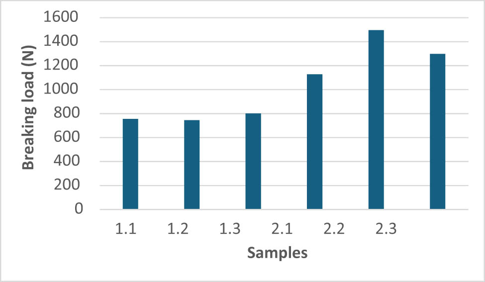
Breaking force under ball compression load.
The results of the breaking force under ball compression load show that the breaking force increases slightly with increasing PU foam thickness, but the breaking force values of samples 1.1, 1.2, and 1.3 do not differ significantly and lie between 755 and 801 N. As expected, there are greater differences in the breaking force for samples 2.1, 2.2, and 2.3, which consist of PU foam and 3D warp knitted spacer fabric. The values of the breaking force under compression load for these samples are between 1,128 and 1,194 N, which speaks in favor of the samples in which part of the PU foam was replaced by 3D warp knitted spacer fabric. As expected, the breaking force of samples 2.1, 2.2, and 2.3 increases with increasing thickness. The highest breaking force was measured for sample 2.2, which contains 50% PU foam and 50% 3D fabric, which is somewhat unexpected.
This is most likely due to the flame lamination process, where the top layer of PU foam is softened with a flame, which then acts as a binder that bonds the PU foam to the 3D fabric in the further process [4]. Sample 2.2 also has a slightly lower thickness after lamination than before lamination.
It was assumed that for this sample (sample 2.2), a proportion of 3D fabric and PU foam that is 50% of the total thickness of the laminate for both layers leads to a higher force required to break the sample under compressive loading with a ball.
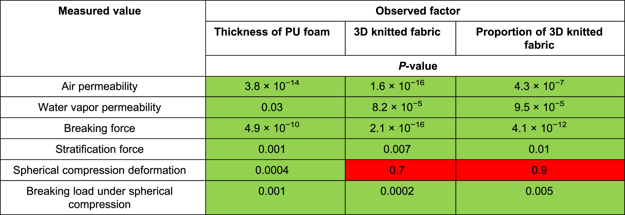
3.9 Statistical analysis
Statistical analysis is shown in Table 6.
Statistical analysis ANOVA
 |
If the p-value is 0.05 or less, the result is considered significant and the null hypothesis is rejected, which means that there are differences between the classes and that these differences are statistically significant.
The statistical analysis using one-way ANOVA [36] shows the statistically significant influence of the thickness of the PU foam, the 3D warp knitted spacer fabric incorporation, and the proportion of 3D warp knitted spacer fabric incorporation in the laminate on the air permeability, the water vapor permeability, the breaking force, the stratification force, the ball compression breaking force, and deformation (p-value <0.05) (Table 6). Statistical analysis, by means of one-way ANOVA, shows the statistically non-significant influence of the 3D warp knitted spacer fabric incorporation and proportion of the 3D warp knitted spacer fabric incorporation on ball compression deformation (p-value >0.05) (Table 6).
4 Conclusion
The aim of this study was to investigate the effect of laminating a three-dimensional structure on polyurethane foam compared to a laminate on which two layers of two-dimensional knitted fabric are laminated. The focus of the investigation was on the influence of the 3D warp knitted spacer fabric on the permeability and some exposed mechanical properties, which are considered important functional properties of laminates for car seats. The influence of the sample thickness is divided into the thickness of the PU foam and the thickness or proportion of the 3D structure. It was found that as the proportion of 3D structure increases, the air permeability, breaking force, and elongation as well as the compressive strength increase, while the water vapor permeability of the proportion of the 3D structure less than 50%, stratification force, and deformation under ball compression load decrease.
It was also found that as the thickness of the PU foam increases, the air permeability and stratification force of the laminates decrease, while the water vapor permeability, breaking force, elongation, and deformation under compression load of the laminates increase. The addition of a 3D warp knitted spacer fabric to the foam has the greatest effect on increasing the air permeability, the water vapor permeability, and the breaking strength under tensile and compressive loads are also improved by the proportion of the 3D warp knitted spacer fabric, which is 40% of the total thickness of the laminate. When the higher values for air permeability and breaking strength are achieved, a larger volume of air flows through the car seat cover, which means that the heaters warm the car seat faster, less energy is consumed, and no overheating occurs. On the other hand, the higher strength of laminates with added 3D warp knitted spacer fabric was achieved under tensile and compression loads. It was found that the stratification forces were comparable in the longitudinal and transverse directions. The lamination was uniform over the length and width of the laminate, which means that the lamination process had no influence on the permeability and mechanical properties in the machine direction (MD) and cross direction (CD).
The following conclusions can be drawn from the present study:
With a sample thickness of more than 7.5 mm, the added 3D warp knitted spacer fabrics in proportions of 40–60% significantly increases the air permeability of the laminates compared to PU foam.
Laminates with 3D warp knitted spacer fabrics in a proportion of 40% of the total thickness of the laminate with a thickness of more than 7.5 mm have the highest water vapor permeability.
Laminates with 3D warp knitted spacer fabrics in proportions of 50 and 60% with a thickness of more than 7.5 mm have a greatly increased strength under tensile load.
Laminates with a thickness of more than 7.5 mm and a proportion of 3D warp knitted spacer fabric of 40% achieve the highest delamination force and deformation under compression load, whereby the highest strength under compression load is achieved with a 3D warp knitted spacer fabric proportion of 50% and a thickness of more than 7.5 mm.
Acknowledgments
This research was funded by the Slovenian Research Agency, Slovenia (Program P2-0213 Textile and Ecology and Infrastructural Centre RIC UL-NTF).
-
Funding information: This research was funded by the Slovenian Research Agency, Slovenia (Program P2-0213 Textile and Ecology and Infrastructural Centre RIC UL-NTF).
-
Author contributions: Conceptualization, methodology, formal analysis, investigation, data curation, writing–original draft preparation, writing–review and editing, D.Š.G.
-
Conflict of interest: Author states no conflict of interest.
-
Data availability statement: The datasets generated during and/or analysed during the current study are available from the corresponding author on reasonable request.
References
[1] Fung, W. (2002). Coated and laminated textiles (pp. 194–208, 1st ed.), Woodhead Publishing Limited (Cambridge).10.1533/9781855737518.1Search in Google Scholar
[2] Shishoo, R. (2008). Textile advances in the automotive industry (pp. 43–59, 1st ed.), Woodhead Publishing (Manchester).10.1533/9781845695040Search in Google Scholar
[3] Fung, W., Hardcastle, J. M. (2000). Textiles in automotive engineering (pp. 44–106, 1st ed.), Woodhead Publishing Limited (Cambridge).10.1533/9781855738973.44Search in Google Scholar
[4] Dejene, B. K., Gudayu, A. D. (2024). Exploring the potential of 3D woven and knitted spacer fabrics in technical textiles: A critical review. Journal of Industrial Textiles, 54, 1–55. 10.1177/15280837241253614.Search in Google Scholar
[5] Arumugam, V., Mishra, R., Militky, J., Davies, L., Slater, S. (2018). Thermal and water vapor transmission through porous warp knitted 3D spacer fabrics for car upholstery applications. The Journal of The Textile Institute, 109(3), 345–357. 10.1080/00405000.2017.1347023.Search in Google Scholar
[6] Arumugam, V., Mishra, R., Militky, J., Kremenakova, D., Tomkova, B., Venkataraman, M. (2019). Thermo-physiological properties of 3D warp knitted spacer fabrics for car seat application. Indian Journal of Fibre & Textile Research (IJFTR), 44(4), 475–485.Search in Google Scholar
[7] Datta, M. K., Behera, B. K., Goyal, A. (2018). Prediction and analysis of compression behaviour of warp-knitted spacer fabric with cylindrical surface. Journal of Industrial Textiles, 48(9), 1489–1504. 10.1177/1528083718769936.Search in Google Scholar
[8] Song, W., Ma, X., Ma, P. (2024). Compression behavior of warp-knitted spacer fabric based on simplified finite element method. Journal of Industrial Textiles, 54, 1–24. 10.1177/15280837241267775.Search in Google Scholar
[9] Chan, M. K., Li, P. L., Yick, K. L., Yip, J., Ng, S. -P. (2024). Exploration of textile–silicone composites and materials for personal impact-resistant protection. Materials, 17, 1439.10.3390/ma17061439Search in Google Scholar PubMed PubMed Central
[10] Li, N. W., Yick, K. L., Yu, A., Ning, S. (2022). Mechanical and thermal behaviours of weft-knitted spacer fabric structure with inlays for insole applications. Polymers, 14, 619.10.3390/polym14030619Search in Google Scholar PubMed PubMed Central
[11] Stylios, G. K., Jones, I. (2013). Joining textiles (pp. 309–347, 1st ed.), Woodhead Publishing (Cambridge).Search in Google Scholar
[12] Fridrichová, L. (2022). Investigation of loss of shape stability in textile laminates using the buckling method. Polymers, 14, 4527.10.3390/polym14214527Search in Google Scholar PubMed PubMed Central
[13] Sen, A. K. (2008). Coated textiles: principles and applications (pp. 87–96, 2nd ed.), CRC Press (London).Search in Google Scholar
[14] Norris, G. A. (2001). Integrating life cycle cost analysis and LCA. International Journal of Life Cycle Assessment, 6(2), 118–120.10.1007/BF02977849Search in Google Scholar
[15] Horrocks, A. R., Anand, S. C. (2000). Handbook of technical textiles (pp. 173–186, 1st ed.), Woodhead Publishing Limited (Cambridge).10.1201/9781439822906Search in Google Scholar
[16] Roshan, P. (2019). High performance technical textiles (pp. 354–379, 1st ed.), John Wiley & Sons (Hoboken).Search in Google Scholar
[17] Singha, K. A. (2012). Review on coating & lamination in textiles: processes and applications. American Journal of Polymer Science, 2(3), 39–49.10.5923/j.ajps.20120203.04Search in Google Scholar
[18] Omerogullari Basyigit, Z. (2019). Improvement of multifunctional automotive textile. Textile and Apparel, 29(2), 113–120. 10.32710/tekstilvekonfeksiyon.475490Gama.Search in Google Scholar
[19] Gama, N. V., Ferreira, A., Barros-Timmons, A. (2018). Polyurethane foams: Past, present, and future. Materials, 11, 1841.10.3390/ma11101841Search in Google Scholar PubMed PubMed Central
[20] Shabani, A., Fathi, A., Erlwein, S., Altstädt, V. (2021). Thermoplastic polyurethane foams: From autoclave batch foaming to bead foam extrusion. Journal of Cellular Plastics, 57(4), 391–411.10.1177/0021955X20912201Search in Google Scholar
[21] Ates, M., Karadag, S., Eker, A. A., Eker, B. (2022). Polyurethane foam materials and their industrial applications. Polymer International, 71(10), 1157–1163.10.1002/pi.6441Search in Google Scholar
[22] Kurańska, M., Beneš, H., Sałasińska, K., Prociak, A., Malewska, E., Polaczek, K. (2020). Development and characterization of “green open-cell polyurethane foams” with reduced flammability. Materials, 13, 5459.10.3390/ma13235459Search in Google Scholar PubMed PubMed Central
[23] Kurańska, M., Barczewski, R., Barczewski, M., Prociak, A., Polaczek, K. (2020). Thermal insulation and sound absorption properties of open-cell polyurethane foams modified with bio-polyol based on used cooking oil. Materials, 13, 5673.10.3390/ma13245673Search in Google Scholar PubMed PubMed Central
[24] Ye, X., Hu, H., Feng, X. (2008). Development of the warp knitted spacer fabrics for cushion applications. Journal of Industrial Textiles, 37(3), 213–223.10.1177/1528083707081592Search in Google Scholar
[25] Gokarneshan, N. (2018). Knit spacer fabrics: Design, properties, and applications (p. 221, 1st ed.), Springer, (Singapore).Search in Google Scholar
[26] Yip, J., Ng, S. P. (2008). Study of three-dimensional spacer fabrics: Physical and mechanical properties. Journal of Materials Processing Technology, 206(1–3), 359–364.10.1016/j.jmatprotec.2007.12.073Search in Google Scholar
[27] Razieh, A., Hasani, H., Soltani, P., Talebi, Z. (2020). Experimental and computational analysis of acoustic characteristics of warp-knitted spacer fabrics. The Journal of The Textile Institute, 111(4), 491–498.10.1080/00405000.2019.1648140Search in Google Scholar
[28] Chen, X. (2015). Advances in 3D textiles (pp. 132–143, 1st ed.), Woodhead Publishing (Cambridge).Search in Google Scholar
[29] ISO 5084. (1999). Textiles – Determination of thickness of textiles and textile products, ISO (Geneva, Switzerland).Search in Google Scholar
[30] ISO 3801. (1996). Textiles – Woven fabrics – Determination of mass per unit length and mass per unit area, ISO (Geneva, Switzerland).Search in Google Scholar
[31] ISO 9237. (1995). Textiles – Determination of permeability of fabrics to air, ISO (Geneva, Switzerland).Search in Google Scholar
[32] ASTM E96:E96M. (2014). Standard test methods for water vapor transmission of materials, ASTM (West Conshohocken, PA, USA).Search in Google Scholar
[33] ISO 1798. (2009). Flexible cellular polymeric materials – Determination of tensile strength and elongation at break, ISO (Geneva, Switzerland).Search in Google Scholar
[34] ISO 13938-2. (2019). Standard Test Method for Determination of bursting strength and bursting distension, ISO (Geneva, Switzerland).Search in Google Scholar
[35] ISO 2411. (2017). Rubber- or plastics-coated fabrics – Determination of coating adhesion, ISO (Geneva, Switzerland).Search in Google Scholar
[36] Chatfield, C. (2018). Statistics for technology. A course in applied statistics (p. 381, 3rd ed.), CRC Press (Boca Raton).10.1201/9780203738467Search in Google Scholar
© 2025 the author(s), published by De Gruyter
This work is licensed under the Creative Commons Attribution 4.0 International License.
Articles in the same Issue
- Study and restoration of the costume of the HuoLang (Peddler) in the Ming Dynasty of China
- Texture mapping of warp knitted shoe upper based on ARAP parameterization method
- Extraction and characterization of natural fibre from Ethiopian Typha latifolia leaf plant
- The effect of the difference in female body shapes on clothing fitting
- Structure and physical properties of BioPBS melt-blown nonwovens
- Optimized model formulation through product mix scheduling for profit maximization in the apparel industry
- Fabric pattern recognition using image processing and AHP method
- Optimal dimension design of high-temperature superconducting levitation weft insertion guideway
- Color analysis and performance optimization of 3D virtual simulation knitted fabrics
- Analyzing the effects of Covid-19 pandemic on Turkish women workers in clothing sector
- Closed-loop supply chain for recycling of waste clothing: A comparison of two different modes
- Personalized design of clothing pattern based on KE and IPSO-BP neural network
- 3D modeling of transport properties on the surface of a textronic structure produced using a physical vapor deposition process
- Optimization of particle swarm for force uniformity of personalized 3D printed insoles
- Development of auxetic shoulder straps for sport backpacks with improved thermal comfort
- Image recognition method of cashmere and wool based on SVM-RFE selection with three types of features
- Construction and analysis of yarn tension model in the process of electromagnetic weft insertion
- Influence of spacer fabric on functionality of laminates
- Design and development of a fibrous structure for the potential treatment of spinal cord injury using parametric modelling in Rhinoceros 3D®
- The effect of the process conditions and lubricant application on the quality of yarns produced by mechanical recycling of denim-like fabrics
- Textile fabrics abrasion resistance – The instrumental method for end point assessment
- CFD modeling of heat transfer through composites for protective gloves containing aerogel and Parylene C coatings supported by micro-CT and thermography
- Comparative study on the compressive performance of honeycomb structures fabricated by stereo lithography apparatus
- Effect of cyclic fastening–unfastening and interruption of current flowing through a snap fastener electrical connector on its resistance
- NIRS identification of cashmere and wool fibers based on spare representation and improved AdaBoost algorithm
- Biο-based surfactants derived frοm Mesembryanthemum crystallinum and Salsοla vermiculata: Pοtential applicatiοns in textile prοductiοn
- Predicted sewing thread consumption using neural network method based on the physical and structural parameters of knitted fabrics
- Research on user behavior of traditional Chinese medicine therapeutic smart clothing
- Effect of construction parameters on faux fur knitted fabric properties
- The use of innovative sewing machines to produce two prototypes of women’s skirts
- Numerical simulation of upper garment pieces-body under different ease allowances based on the finite element contact model
- The phenomenon of celebrity fashion Businesses and Their impact on mainstream fashion
- Marketing traditional textile dyeing in China: A dual-method approach of tie-dye using grounded theory and the Kano model
- Contamination of firefighter protective clothing by phthalates
- Sustainability and fast fashion: Understanding Turkish generation Z for developing strategy
- Digital tax systems and innovation in textile manufacturing
- Applying Ant Colony Algorithm for transport optimization in textile industry supply chain
- Innovative elastomeric yarns obtained from poly(ether-ester) staple fiber and its blends with other fibers by ring and compact spinning: Fabrication and mechanical properties
- Design and 3D simulation of open topping-on structured crochet fabric
- The impact of thermal‒moisture comfort and material properties of calf compression sleeves on individuals jogging performance
- Calculation and prediction of thread consumption in technical textile products using the neural network method