CFD modeling of heat transfer through composites for protective gloves containing aerogel and Parylene C coatings supported by micro-CT and thermography
-
Pamela Miśkiewicz
 ,
Adam K. Puszkarz
and
Andrzej Nosal
,
Adam K. Puszkarz
and
Andrzej Nosal

Abstract
The research presented in this article concerns the modeling of physical processes occurring in protective clothing that determine the ergonomics and thermal balance between its user and the work environment. In the first part, three-dimensional models of real composites based on cotton fabrics and aerogel were designed using the original method of Parylene C deposition in the chemical vapour deposition (CVD) process, which have potential application in thermal protective gloves. The models included geometric parameters of real textiles calculated based on high-resolution X-ray tomography. This technique also allowed for the accurate determination of the porosity of the tested materials and the inclusion of the exact air content in the models without the need to reproduce the complex geometry of fibers in the fabric and microgranules in the aerogel. The results of heat transfer simulations performed using the finite volume method, correlating with the results of the experiment verifying them using thermography, showed that the designed models allow for the prediction of heat transfer with high accuracy despite the use of a lot of simplifications in the geometry. The differences between the modeling results and the experiment range from 0.7 to 5.5% depending on the complexity of the model geometry.
1 Introduction
Cotton fiber is a natural fiber consisting of approximately 88–96% pure cellulose [1,2]. The cotton plant is grown mainly in desert and arid areas because its crops are resistant to demanding climatic conditions [3]. In the world, 2.1% of agricultural land is used for cotton cultivation. Cotton fibers are used in the textile industry due to their very good properties, i.e., air permeability, biodegradability, hygroscopicity and lack of static electricity [1,4,5]. Cotton is a natural, bio-based and common textile material, used in various clothing, transport, dressings, coffee filters, fishing nets, etc. [5].
Parylene technology is an unusual type of physical vapor deposition process, which uses organic polymers. Parylene (poly-para-xylylene-based polymer) is a polycrystalline, crystal-clear and amorphous linear polymer [6]. Parylene adapts very well to the substrate, as it has good adhesion [7]. Among the parylene coatings, we can distinguish: Parylene N, C and D. Parylene C shows chemical resistance, thermal stability and resistance to moisture. Moreover, Parylene C is the best moisture barrier in relation to Parylene N and D. Additionally, it shows high biocompatibility and biostability [6,8]. In summary, Parylene C is a universal material suitable for applications in flexible materials [9]. One of the interesting aspects of parylene coatings is that they can be conformally coated on any geometry, mainly on objects with deep holes and cracks. Parylene coatings are chemically neutral, smooth and transparent and cannot be dissolved in commonly used solvents [10,11]. Additionally, they exhibit low gas permeability and constitute a very good barrier to ion diffusion. Parylene coatings exhibit high dielectric strength and better-insulating properties compared to silicone polymers commonly used to insulate electrical circuits [6,7,12]. In addition, they have useful elastic properties (deformation) and high resistance to tearing, thanks to which they are used as slip coatings in biomedicine [13]. They are also used in electrical circuits, as they provide protection against corrosion. Moreover, due to their low level of water, gas and ion permeability and low level of friction, they are used in pacemakers, implants and prostheses. Parylene coatings are also used to protect elements of nature [11,14].
Aerogels are ultralight solids, highly porous and semi-transparent, consisting of more than 90% air [15]. They are available in the form of powder or granulate. According to the International Union of Pure and Applied Chemistry, aerogel is a gel consisting of a microporous solid substance in which the dispersed phase is a gas [15,16]. Aerogels are characterized by a low refractive index, low density of 3–150 kg m−3 and a dielectric constant, high shock absorption capacity and a specific surface area of 500–1,200 m2 g−1. In addition, they exhibit low sound velocity and low thermal conductivity of 0.005–0.015 W m−1 °C−1 [15,16,17]. The unique and diverse properties of aerogels allow them to be used in a wide range of applications. Starting from thermal insulation (e.g., in construction, clothing and spacecraft), through solar windows, sensors, acoustic insulation, filtering agents and kinetic energy absorbers [18,19].
The most used aerogels are based on silica, while other aerogels, e.g., based on carbon monoxide, aluminum, titanium and zirconium [20,21] are used much less frequently. The structure of silica aerogel is made of solid particles with a diameter of 1–10 nm, connected with each other by covalent bonds. They form a stable network with small but numerous pores with a diameter of 10–100 nm [15,16,17]. In reference to the structure of the aerogel, it should be noted that the share of the solid fraction, i.e., silicon dioxide, is up to 10%, while the rest is air. Due to this fact, aerogels have the lowest density as solids [22,23].
Aerogels are characterized by low thermal conductivity of up to 0.02 W m−1 °C−1 due to high porosity and very small pores. This parameter is substantially lower in relation to traditional materials, and also lower than in the case of still air (0.026 W m−1 °C−1) [15,16,17,18,19]. Billions of irregularly shaped pores and a large specific surface area of aerogels result in their heat capacity being 2–6 times greater than commonly used materials. Among the advantages of aerogels, one should mention their low density, which allows the production of ultralight materials. In addition, silica aerogels have good fire-resistant properties, which may contribute to their use, among others, in clothing protecting against hot factors [24]. The biggest disadvantage of aerogels is the high production cost caused by the energy-intensive and time-consuming production process. Another major disadvantage of silica aerogels is their fragility and very high tendency to dust during their manipulation [21,25]. The disadvantages presented significantly limit the use of aerogel in its pure form. In order to use it, for example, in clothing to increase its thermal insulation properties, its proper application to the textile material is necessary [15,16,17,18,21].
Shaid et al. conducted research on the application of aerogels to wool-aramid fabrics used to manufacture firefighter clothing. The fabrics were coated with an acrylic binder containing silica aerogel in various amounts and subjected to a 10-min treatment at 105°C. It was found that even 2% aerogel content in the coating significantly improved the thermal insulation properties of the material. The thermal resistance of the fabric modified with aerogel was 0.0199 m2 °C−1 W−1 [26].
Miśkiewicz et al. used a technique of coating basalt fabric with an adhesive mixture containing silica aerogel. The mixture consisted of: aerogel, adhesive, wetting agent and flame retardant. By applying aerogel to the fabric surface, its resistance to contact heat was improved. The obtained results of fabric resistance to thermal radiation also proved the beneficial effect of aerogel [27].
Krzemińska et al. worked on various fabric packages that contained tunnels filled with aerogel. The packages were made in the form of removable inserts that were to be placed in the pockets of clothing from the inside. The inserts produced differed not only in the external material but also in their construction, as they contained 6, 7 or 10 tunnels filled with aerogel. The packages obtained were characterized by at least twice as much resistance to thermal radiation and convection heat and showed increased resistance to contact heat for a contact temperature of 250°C. A better effect was obtained for packages with a larger number of tunnels [15].
The first research on the use of aerogel materials in clothing was initiated by NASA and concerned space suits [28].
In response to NASA’s needs, Aspen Aerogels from the United States produced a flexible nonwoven composite containing aerogel (aerogel blanket) under the trade name Spaceloft™. The composite was three times more effective compared to the best clothing insulation on the market. In subsequent years, CorpoNove applied the same composite to winter jackets, which were tested during an expedition to Antarctica [15,16,29].
Modeling the structure of materials and simulations of physical or chemical phenomena occurring inside them is an increasingly popular tool supporting experimental research. When it comes to materials used in protective clothing, the most common phenomena that are the subject of modeling are those related to the safety of the user of this clothing, their physiological comfort [30,31,32,33] or ergonomics [34,35,36,37,38,39]. In these cases, the subject of modeling is the mechanical properties of materials (e.g., resistance to impact, puncture, cutting or abrasion) [40,41,42,43] and thermal properties (e.g., thermal insulation or resistance to extreme temperatures). The increasing computing power of computer equipment and the development of specialist software enable the design of increasingly accurate material models, reflecting the spatial geometry of actual materials with increasing precision and allowing for the modeling of complex phenomena occurring during the analyzed process. Modeling phenomena inside models of real materials used in protective clothing, in addition to examining the relationship between its structure and its functional properties, enables the prediction of key critical parameters of clothing regulated by standards guaranteeing user safety [44,45,46,47,48,49,50].
The research presented in this article is the next stage of study on modeling heat transfer phenomena in protective clothing [51,52,53,54] in which this time a composite made of an aerogel layer cross-linked with Parylene C deposited using chemical vapor deposition, chemical vapor deposition (CVD) technology and combined with cotton fabric was proposed as a thermal insulation layer. The subject of the research was cotton fabrics and composites of various geometry and raw material compositions containing aerogel and Parylene C coatings with potential use in thermal protective gloves intended for firefighters, paramedics or workers in the metallurgical industry.
In the main part of the research 3D models of fabrics and composites were designed using CAD software, in which heat transfer simulations were performed in selected environmental conditions. X-ray microtomography (micro-CT) was used to precisely reproduce the geometry in the micro scale of the designed models and the geometric parameters of real textiles. Microtomography, in addition to precise determination of geometric parameters of fabrics (fabric thickness, shape and diameter of yarn), aerogel (layer thickness, wall thickness in microgranules) and Parylene C coating (coating thickness, its content in fabric or aerogel), enabled precise determination of air content (porosity) in the tested materials, which is a key factor determining their thermal insulation properties. Moreover, in the case of fabrics, in addition to total porosity, it was possible to determine the porosity of the yarn, while in the case of aerogel, additionally, closed porosity was determined at the microscale level. Accurate measurements of air content in the tested fabrics and composites allowed for the use of homogenization and taking into account the representation of the actual porosity of the tested materials in the models without the need to reproduce the complex arrangement of individual fibers in the fabric and the chaotic spatial distribution of granules in the aerogel. The results of heat transport simulations in the designed fabric and composite 3D models were validated using experiments conducted under the same ambient conditions with actual materials using a hot plate and a thermography.
2 Experimental
2.1 Materials
The subject of the study was two cotton fabrics (unmodified and with a Parylene C coating applied using CVD technology) and two composites, the main layer of which was an ENOVA® IC3110 aerogel (particle size range: 0.1–0.7 mm; pore diameter: ∼20 nm; particle density: 120–150 kg m−3; surface chemistry: hydrophobic; thermal conductivity: 0.012 W m−1 °C−1) made by Cabot Corporation (Boston, Massachusetts, USA) [53].
In the two-layer composite α, the aerogel layer and the cotton fabric were permanently bonded via a deposited Parylene C coating via the CVD chemical vapor deposition process. The two-layer α composite was the starting product for obtaining the final three-layer composite β, which, in addition to the two above-mentioned layers, also contained an unmodified cotton fabric (which could simultaneously act as a thermal insulation layer and, thanks to the unmodified cotton fibers ensuring sensory comfort, as a lining).
To produce the composite β, an innovative method of combining layers was used, which simultaneously ensured the durability of the connection of all three layers of the composite while maintaining its resistance to high temperatures prevailing in the work environment of the glove user. Modification of the cotton fabric and aerogel surface by deposition of Parylene C using the CVD technique enabled increased adhesion of both layers and ensured a more durable connection of all three layers in the composite. In addition, Parylene C, which penetrated deeply into the aerogel layer, contributed to a better connection of its microgranules and thus improved the mechanical durability of this composite layer. The technology of obtaining the composite β was described in more detail in the patent application [54].
The structure scheme and photos of both composites are presented in Figure 1, while the geometric parameters of the fabrics and composites are presented in Table 1.
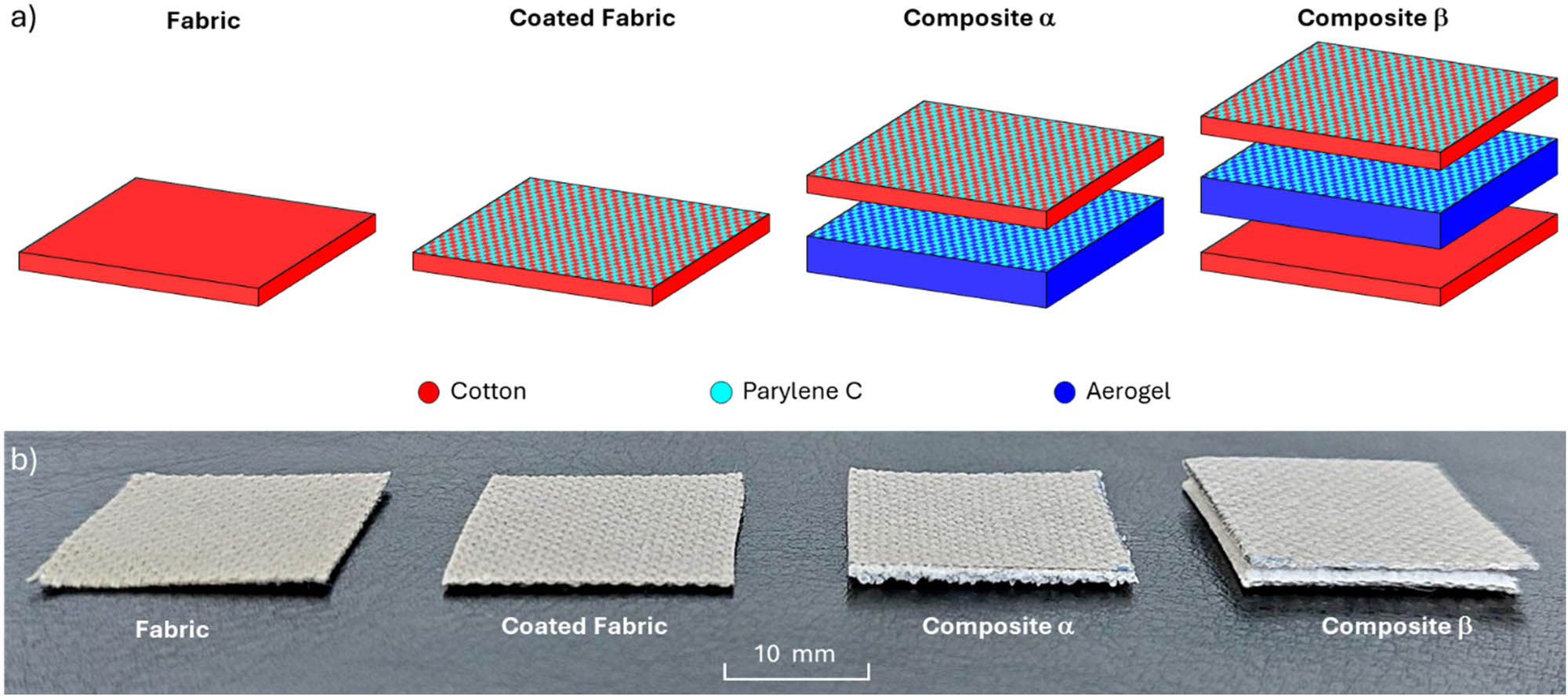
(a) Construction scheme and (b) photos of two tested fabrics and two composites.
Physical parameters of tested fabrics and composites
| Sample name | Layer composition | Thickness (µm) | Mass per unit area (g m−2) | Weave | |
|---|---|---|---|---|---|
| Fabric | Cotton fabric | 440 | 214.00 | Warp rib (2/2) | |
| Coated fabric | Cotton fabric with Parylene C coating | 460 | 326.74 | Warp rib (2/2) | |
| Composite α | Cotton fabric with Parylene C coating | 460 | 1,360 | 494.62 | Warp rib (2/2) |
| Aerogel with Parylene C coating | 900 | ||||
| Composite β | Cotton fabric with Parylene C coating | 460 | 1,800 | 919.12 | Warp rib (2/2) |
| Aerogel with Parylene C coating | 900 | ||||
| Cotton Fabric | 440 | ||||
The use of aerogel, due to its low thermal conductivity and hydrophobic surface, enables their potential use as a thermally insulating layer in gloves protecting the user from a hot work environment. The use of cotton fabric can provide proper physiological comfort (affecting the appropriate thermal balance between the user and their environment) and sensory comfort, in the case when the fabric will act as a lining in the glove.
The outcomes shown in Table 1 show that the sum of the component layer thicknesses of both composites is greater than the thickness of the composites. Parylene C coatings were applied to both substrates using the Specialty Coating System (Indianapolis, IN, USA), the scheme of which is shown in Figure 2. A more detailed description of the technology used was presented in the authors’ earlier work devoted to the study of the effect of Parylene C coatings on the performance properties of flame-retardant fabrics [6].
![Figure 2
Scheme of Parylene C coating method [54].](/document/doi/10.1515/aut-2025-0042/asset/graphic/j_aut-2025-0042_fig_002.jpg)
Scheme of Parylene C coating method [54].
The modification of the fabric and aerogel surfaces by deposition of Parylene C was used to increase the adhesion of both layers and ensure a more durable connection of both layers in the composites. In addition, Parylene C, which penetrated deep into the aerogel layer, contributed to a better connection of its microgranules and thus improved the mechanical strength of this composite layer.
2.2 Methods
2.2.1 Material structure analysis
Thickness and mass per unit area of tested fabrics and composites were calculated according to PN-EN ISO 5084:1999 and PN-EN 12127:2000, respectively [55,56].
Using optical microscopy, OM (Delta Optical Smart 5MP PRO, Delta Optical, Warsaw, Poland) equipped with firmware: Delta Optical Smart Analysis Pro 1.0.0), the following was performed:
The photos of the fabric and aerogel surface were obtained and
Identification of the report and weave in fabric.
Using micro-CT (SkyScan 1272; Bruker, Kontich, Belgium), the following was performed:
Statistical distributions of the thickness of the matter in the component layers of both composites: in fabrics (cotton fibers, Parylene C coating deposited on the fibers) and in aerogel (wall thickness of aerogel microgranules, thickness of Parylene C coating on aerogel granules),
Parylene C coating volume per unit area of fabric,
Parylene C coating volume per unit area of aerogel, and
3D visualizations tested fabrics and composites.
2.2.2 Thermal imaging
To study the impact of the fabrics and composites on their thermal insulation properties, an experiment was carried out using a flat heated plate (e-G51HP07C Guardian 5000 model, OHAUS Europe GmbH) and a thermal imaging camera (FLIR SC 5000 model made in Wilsonville). The scheme of thermal imaging is shown in Figure 3.
![Figure 3
Scheme of thermal imaging [54].](/document/doi/10.1515/aut-2025-0042/asset/graphic/j_aut-2025-0042_fig_003.jpg)
Scheme of thermal imaging [54].
Both fabrics and both composites were placed on the surface of the plate at a constant temperature T p of 50°C at an ambient temperature T a of 23°C. As a result of the difference in temperature between the plate and the environment (equal to 27°C), heat was transferred from the plate to the colder surroundings through the fabrics and composites lying on the plate. Due to the heat flow, the samples gradually heated up from the heat flowing from the plate and after some time their temperature stabilized at a certain constant maximum value T top. The increase in temperature over time of the upper surface of the fabrics and composites was continuously recorded by a thermal imaging camera placed above the plate.
2.2.3 Model designing
Three-dimensional models of real fabrics and composites presented in Figure 4 were designed using the SolidWorks 2014 (SP 3.0) CAD software [57].
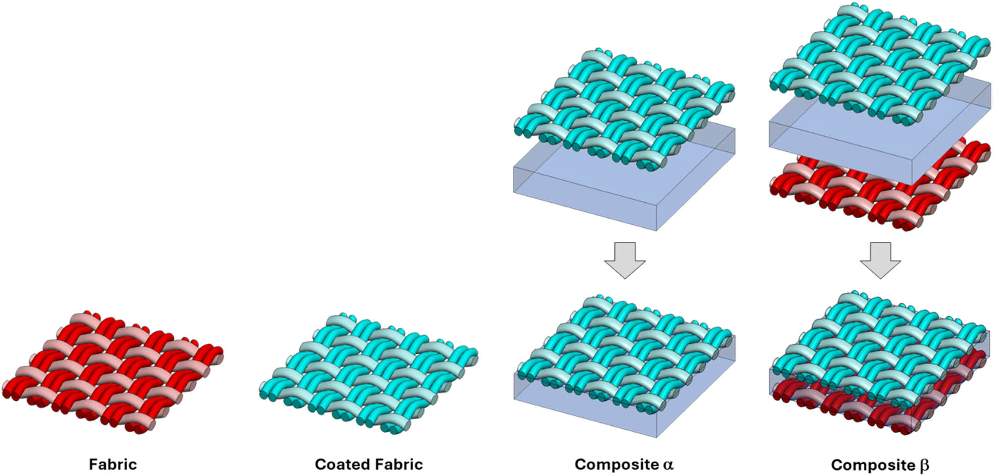
3D models of two tested fabrics and two composites (dimensions 5.01 mm × 4.86 mm).
The following geometric parameters were modeled during the design of the cotton fabric: (1) fabric thickness, (2) weave, (3) warp density, (4) weft density, (5) yarn thickness, and (6) elliptical shape and cross-sectional size of the warp and weft yarns. The yarns are designed as monofilaments (the fibers in the yarn and the spaces between them are not reproduced). The layer composed of aerogel microgranules was mapped as a cuboid with the actual thickness of the layer (microgranules and free spaces between them filled with air were not mapped). The 3D models of both fabrics and both composites were characterized by the following further simplifications. In the cotton fabric model, the fabric thickness, weave, warp and weft density and yarn diameter were assumed as constant geometrical parameters. In the actual cotton fabric, the yarn geometry is variable, as a result of friction forces of neighboring yarns, its shape changes. In the aerogel layer model, its thickness was assumed to be constant, and the matter distribution was uniform. In reality, the thickness of the aerogel layer in both composites is variable because it depends on the spatial distribution of the aerogel microgranules.
In 3D models of tested fabrics and composites, an essential issue was the correct representation of the air content (porosity) and the content of deposited Parylene C. It was assumed that in the aerogel and in the cotton fabric yarn (both unmodified and coated), their average porosity determined by micro-CT is constant over the entire volume of these materials. The tomography results showed that the deposited Parylene C did not form a uniform continuous layer on the surface of the coated fabric but penetrated the interior of the yarn through the free spaces between the cotton fibers. A similar phenomenon was observed in the case of the aerogel layer, in the shorter case Parylene C penetrated through the free spaces between the granules and settled on their external surface. In connection with the above, air and cotton homogenization was used for the yarn model in the fabric, while air, cotton and Parylene C homogenization was used for the yarn model in the coated fabric. The coated aerogel was similarly modeled, in which the homogenization of aerogel, air and Parylene C was used. The shares of individual raw materials in these models resulted from the mutual proportions in the yarn and the aerogel layer calculated using microtomography. The use of yarn homogenization in cotton fabrics allowed for the presence of air (and Parylene C in the case of coated fabric) in the spaces between the fibers to be taken into account without the need to design them in the model, and for the influence of porous yarn on the thermal insulation properties of both fabrics to be taken into account. In the case of both composites, homogenization allowed for the reproduction of the coated aerogel without the need to reproduce the geometry of the aerogel microgranules, the air filling the free spaces between the microgranules and the geometry of the Parylene C coating present on the outer walls of the microgranules.
The surface of all four models has been reduced to the same size (5.01 mm × 4.86 mm) containing nine fabric reports.
2.2.4 Heat transfer simulations
The designed fabric and composite models were subjected to heat transfer simulations under the same environmental conditions as the experiment using the heated plate and thermography was conducted. The simulations were carried out using the finite volume method using the Solidworks Flow Simulation 2014 software [57]. The software used (Solidworks Flow Simulation 2014) allows modeling heat transfer due to conduction (in solids) and convection (in fluids and solids) using computational fluid dynamics and was used in the authors’ earlier works in the same research area [51,52].
Three-dimensional fabric and composite models were placed on the upper surface of the heated plate model (a cuboid with a constant temperature T p = 50°C), the area of which was identical to the surface area of the fabric and composite models (5.01 mm × 4.86 mm). The heated plate model and the tested model (fabric or composite) were placed inside the computational domain (filled with air at a temperature of T a = 23°C) with side walls adjacent to the side edges of the heated plate model and a height of 7.5 mm (Figure 5).
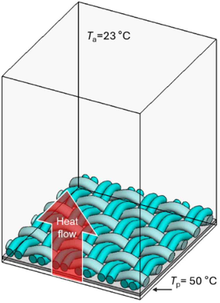
Initial conditions of heat transfer simulations inside computational domain.
To reduce the harmful effect of boundary conditions on the precision of calculations, periodic boundary conditions were imposed on the computational domain, simulating the continuation of the tested model (fabrics or composites) and model of the heated plate outside the computational domain in all four horizontal directions.
Based on the results of the micro-CT structural analysis of the fabric yarn porosity, coated fabric yarn porosity and the porosity of the coated aerogel layer, the homogenization of the raw materials from which these layers were made (presented in Table 2) with air was applied to all four models, maintaining the mutual proportions arising from the computed porosity and the content of a given raw material (cotton, aerogel, Parylene C). Based on the proportions of air and raw materials (with physical parameters presented in Table 2) for each layer of composites, the actual values (weighted average) of these parameters were calculated, i.e., density, specific heat and thermal conductivity coefficient.
| Physical parameter | Cotton | Parylene C | Aerogel | Air |
|---|---|---|---|---|
| Density (kg m−3) | 1,550 | 1,289 | 130 | 1.2 |
| Specific heat (J kg−1 °C−1) | 1,330 | 712 | 1,800 | 1,005 |
| Thermal conductivity (W m−1 °C−1) | 0.072 | 0.08 | 0.012 | 0.03 |
The presented method of designing textile models and the method of homogenization of raw materials used in them and the resulting homogenization of their physical parameters were applied and described in more detail in the authors’ earlier studies [51,52].
3 Results and discussion
3.1 Material structure analysis
Figure 6 shows photographs of the cotton fabric surface (a and b) and the aerogel layer surface (c and d) taken at two different magnifications. The photographs show the fabric weave (warp rib (2/2)) and the size distribution of aerogel microgranules, which according to the manufacturer range from 0.1 to 0.7 mm.
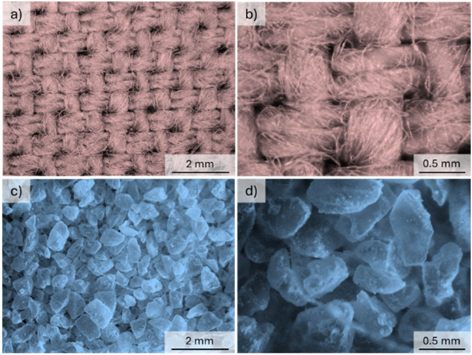
Optical microscopy images of cotton fabric (a and b) and aerogel (c and d).
Figure 7 presents three-dimensional micro-CT visualizations of all four tested materials. Based on the visualization of the coated fabric, it can be observed that the Parylene C deposited using CVD technology did not form a continuous layer on the fabric surface but penetrated into the interior of the porous cotton yarn.
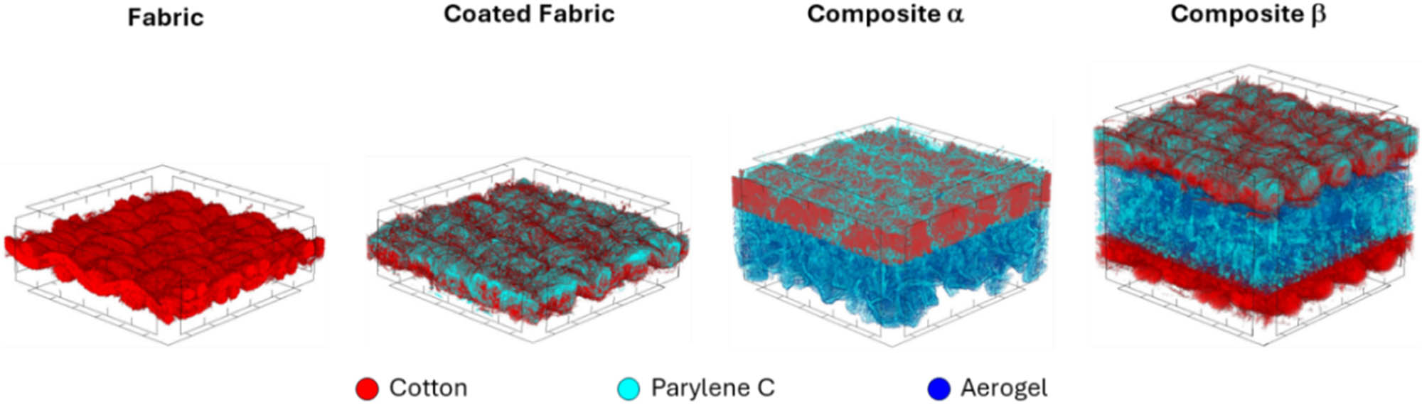
3D micro-CT visualizations of two tested fabrics and two composites (surface area: 3 mm × 3 mm).
A similar phenomenon was observed in the case of the aerogel layer in the composite α and composite β. The loose packing of the aerogel granules allowed the Parylene C particles to penetrate into the layer and form a coating on the outer wall of the microgranules in the entire volume of the aerogel layer.
Figure 8a shows the thickness distributions of the fibers in the fabric yarn, the fibers in the coated fabric yarn and the Parylene C layer in the coated fabric. According to them, it can be stated that the cotton fiber thickness distribution in the fabric is in the range of 4–76 µm. The largest part of the yarn volume in the fabric (45%) is fibers in the range of 13–22 µm, and the average fiber thickness is <d F> = 27 ± 11 µm. As a result of the deposition of Parylene C, the fiber thickness distribution in the coated fabric widened toward higher values and was in the range of 4–130 µm. It is likely that Parylene C penetrated the yarn during deposition and settled on the fibers, causing them to stick together and thus contributing to their thickening. In the case of the coated fabric, the average fiber thickness was <d CF> = 56 ± 28 µm. The Parylene C layer thickness distribution in the coated fabric shows that Parylene C was deposited in layers with thicknesses ranging from 4 to 67 µm, with an average layer thickness of <d P> = 19 ± 8 µm and the amount of Parylene C per unit area of fabric being <V P/F> = 4 mm3 cm−2. Figure 8b shows the effect of Parylene C deposition on the porosity of cotton fabric. According to the results, the deposition of Parylene C reduced the porosity of the yarn by 13% and thus the porosity of the whole fabric by 6%.
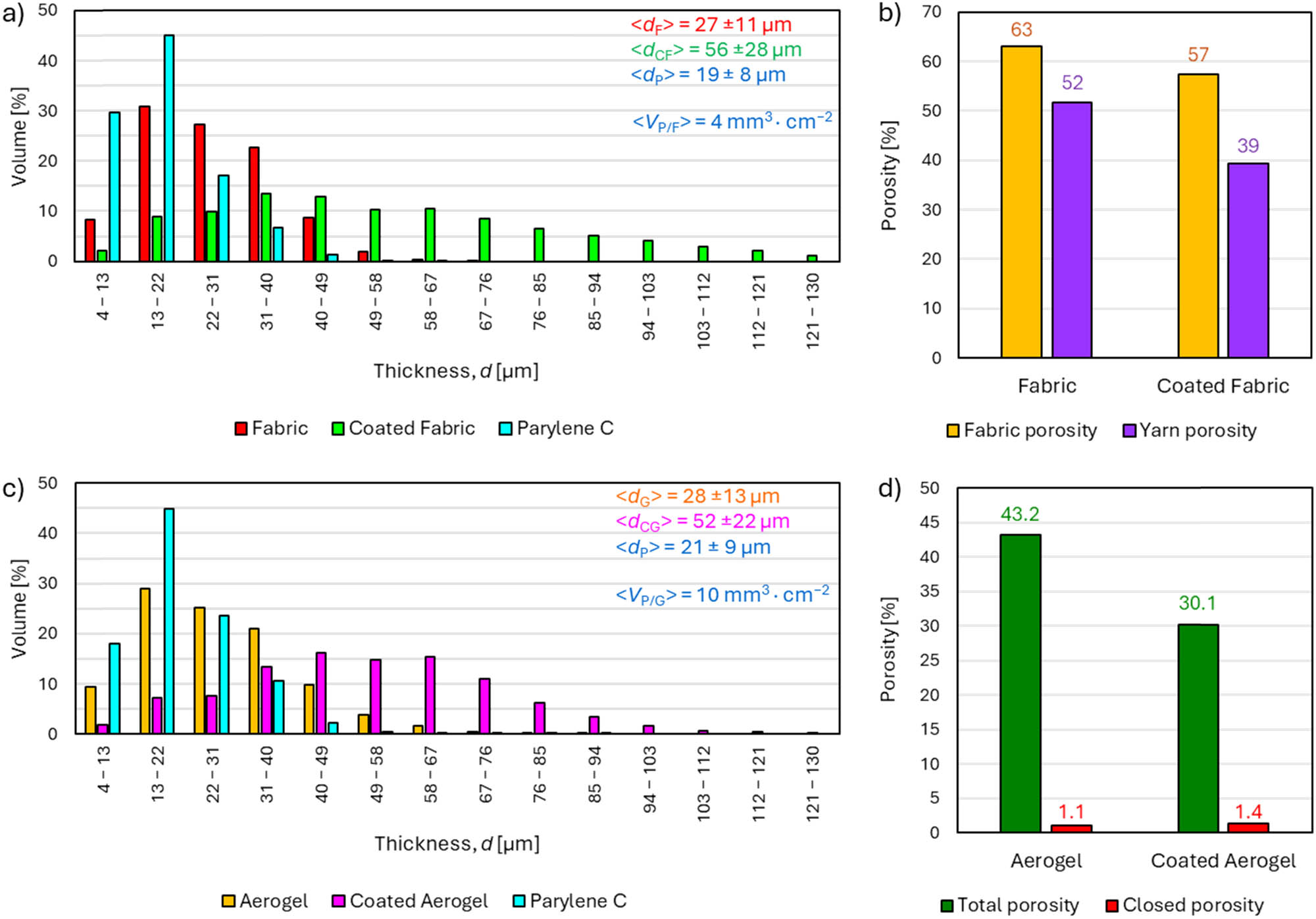
Results of microtomography analysis of tested fabrics and composites. (a) Thickness distribution of fabric, coated fabric and Parylene C coating on fabric; (b) fabric porosity; (c) thickness distribution of aerogel, coated aerogel and Parylene C coating on aerogel; and (d) aerogel porosity.
Figure 8c shows the wall thickness distributions of the aerogel microgranules, the walls of the coated aerogel microgranules and the Parylene C layer on the walls of the aerogel microgranules. According to them, it can be stated that the wall thickness distribution of the aerogel microgranules is in the range of 4–94 µm, and the average wall thickness is <d G> = 28 ± 13 µm. As a result of the deposition of Parylene C, the wall thickness distribution of the coated aerogel broadened toward higher values and was in the range of 4–130 µm. Parylene C, which during deposition penetrated into the interior of the aerogel layer and deposited on the microgranules, caused and in this way contributed to the increase in their size. In the case of the coated aerogel, the average microgranule wall thickness was <d CG> = 52 ± 22 µm. The Parylene C layer thickness distribution in the coated aerogel shows that Parylene C was deposited in layers with thicknesses ranging from 4 to 94 µm, the average layer thickness was <d P> = 21 ± 9 µm, and the amount of Parylene C per unit area of aerogel was <V P/G> = 10 mm3 cm−2. Figure 8d shows the effect of Parylene C deposition on the porosity of the aerogel layer. According to the results, the deposition of Parylene C resulted in a reduction of the total aerogel porosity by 13.1% and a slight increase of the open porosity by 0.3% (probably due to the covering of the open pores in the aerogel microgranules by the Parylene C coating).
3.2 Thermal properties
Figure 9a shows the curves of the dependence of the temperature of the top surface of the tested fabrics and composites, T top on the time of exposure to heat from the heated plate obtained during thermal imaging.
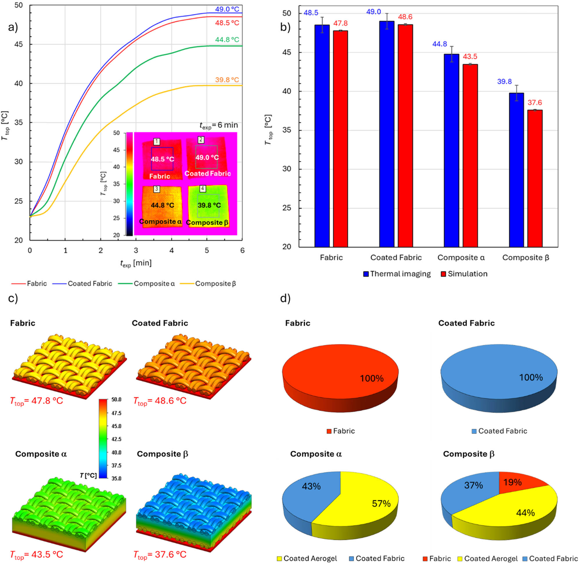
Thermal imaging and simulation results of tested fabrics and composites. (a) Dependence of the temperature of the top surface of the tested fabrics and composites, Ttop on the time of exposure to heat from the heated plate and thermograms obtained during thermal imaging; (b) comparison of the thermal imaging and modeling results; (c) temperature distributions on the surface of the three-dimensional models after reaching the steady state; and (d) heat losses in both fabrics and in individual layers of both composites.
Depending on the geometry and composition of the raw material, these materials reached different maximum temperatures. As expected, the thickest of the tested materials – composite β, which reached a temperature of T top = 39.8°C, proved to be the most thermally insulating material, while the coated fabric, which reached a maximum temperature of T top = 49.0°C, proved to be the least thermally insulating. The unmodified fabric, which reached a maximum temperature of T top = 48.5°C, turned out to be only slightly more thermally insulating. The small but noticeable difference was probably caused by the fact that the deposited Parylene C in the coated fabric reduced its porosity, thus affecting the deterioration of its thermal insulation properties. In the lower right corner of Figure 9a, thermograms showing the temperature distribution on the surface of the tested fabrics and composites at the moment of obtaining a steady state (exposure time – 6 min) are presented. To reduce the negative influence of boundary conditions on the results of the thermal imaging camera measurements, the temperature of the top surface T top of the samples (in the form of squares with a side of about 3 cm) was recorded from the area limited by a square with a side of 2 cm located in the central part of the upper surface of each sample. Figure 9b shows a comparison of the results of the temperature of the upper surface of fabrics and composites obtained by means of thermal imaging and by means of modeling. The results are correlated with each other, however, for each tested material, the T top determined experimentally is higher than the corresponding value determined by means of heat transfer simulations through their three-dimensional models. The greatest agreement of the simulation results with the experimental results was obtained for less complex models of both fabrics. In the case of unmodified fabric, the difference in the T top value is 0.7°C, while for the coated fabric, it is 0.4°C and is within the range of temperature measurement uncertainty (±1°C) resulting from the thermal imaging camera specification. For more complicated models of both composites in spatial geometry, the differences are clearly greater and amount to 1.3°C for composite α and 2.2°C for composite β, respectively. The differences in the deviations of the experimental results from the simulation results may have a number of causes. On the one hand, they may result from the uneven distribution of matter in real fabrics and composites, which was assumed during the design of their three-dimensional models. The reason for the discrepancy in the results could also be the imprecise initial conditions of the modeling, which assumed that all fabrics were perfectly flat and all layers in the composites were perfectly matched to each other, and all materials exactly adhered to the heated plate with their entire lower surface. Figure 9c shows the temperature distributions on the surface of the three-dimensional models after reaching the steady state (6 min of exposure to the heat of the heated plate). The models show a layered horizontal flat temperature distribution, which does not show a negative influence of the boundary conditions, which indicates correctly selected periodic boundary conditions imposed on the computational domain. For each model, the temperature to which the top surface T top of each model was heated after reaching the steady state is given. Based on the modeling results, heat losses in both fabrics and in individual layers of both composites were computed and shown in the pie charts. Based on the modeling results, heat losses in both fabrics and in individual layers of both composites were determined and shown in pie charts in Figure 9d. The charts show that in both composites the thickest layer made of coated aerogel constituted the greatest thermal barrier, retaining 57% of heat in composite α and 44% of heat in composite β.
It should be noted that the presented studies concerned only the problem of thermal insulation as one of several related to the potential use of the composites produced in thermal protective gloves. The composites produced require additional tests of resistance to three types of heat (contact, radiation or flame) conducted according to appropriate safety standards, which will be the aim of further studies. In addition, the composites produced will be tested for resistance to mechanical impact, typical to which the glove is exposed (cyclic bending, compression, tearing, puncture, friction). If the appropriate conditions are met, they will be used to create gloves.
4 Conclusions
The main objective of this study was to model heat transfer through cotton fabrics and composites containing aerogel and Parylene C coatings with potential application in thermal protective gloves. In the experimental part of the work, heat transfer measurements were performed through fabrics and composites under normal ambient conditions using a heated plate and thermal imaging. Then, geometric parameters of fabrics and composites were precisely determined using micro-CT and based on them, three-dimensional models were designed using CAD software. Based on the precise micro-CT analysis of the spatial geometry of the tested materials in the microscale, homogenization was used without the need to map the complicated fiber arrangement in fabrics, Parylene C coatings in fabrics and aerogel in composites. Then, heat transfer simulations were performed through three-dimensional models of fabrics and composites by applying the finite volume method under the same ambient conditions as the experiment was conducted.
By comparing the results obtained in heat transfer modeling and the experiment verifying them, the following conclusions can be drawn:
Reproduction of subtle differences in the spatial geometry and porosity of fabrics and composites (determined by micro-CT) in the designed 3D models revealed noticeable differences in the simulated heat flow,
Despite numerous simplifications in structure and the application of homogenization, the 3D models of tested materials allow for the prediction of heat flow through actual fabrics with a dissimilarity of up to 0.7% and composites up to 5.5% compared to the experimental results,
The used modeling method is a useful way enabling accurate forecast of heat flow through single-layer fabrics and multi-layer composites with complicated spatial geometry before starting the manufacture of protective gloves, which can translate into savings in terms of raw materials, energy and labor costs as well as time needed for their production.
Acknowledgments
These studies were financed using funds assigned from: I42/501-4-42-1-1 statutory activity by the Lodz University of Technology, Textile Institute, Poland, and the “Innovative Textiles 2020+,” no. RPLD.01.01.00-10-0002/17-00, investment project within the Regional Operational Programme for Łódzkie 2014–2020.
-
Funding information: The authors state no funding involved.
-
Author contributions: PM developed the research plan, developed the composite manufacturing method, designed the textile models and performed heat transport simulations and wrote the manuscript. AP characterized the structure of the composites using high-resolution X-ray microtomography, investigated the thermal insulation properties of the composites using thermovision, made photos, diagrams, visualizations and graphs and wrote the manuscript. AN developed a method of chemical deposition of Parylene C coatings enabling the production of composites and wrote the manuscript.
-
Conflict of interest: The authors state no conflict of interest.
-
Ethical approval: The conducted research is not related to either human or animal use.
-
Data availability statement: The datasets generated during and/or analysed during the current study are available from the corresponding author on reasonable request.
References
[1] Bashar, M. M., Khan, M. A. (2013). An overview on surface modification of cotton fiber for apparel use. Journal of Polymers and the Environment, 21, 181–190.10.1007/s10924-012-0476-8Search in Google Scholar
[2] Alebeid, O. K., Zhao, T. (2017). Review on: developing UV protection for cotton fabric. The Journal of The Textile Institute, 108(12), 2027–2039.10.1080/00405000.2017.1311201Search in Google Scholar
[3] Ibrahim, N. A., Nada, A. A., Eid, B. M., Al-Moghazy, M., Hassabo, A. G., Abou-Zeid, N. Y. (2018). Nano-structured metal oxides: synthesis, characterization and application for multifunctional cotton fabric. Advances in Natural Sciences: Nanoscience and Nanotechnology, 9, 035014.10.1088/2043-6254/aadc2cSearch in Google Scholar
[4] Ibrahim, N. A., Emam, E. A. M., Eid, B. M., Tawfik, T. M. (2018). An eco-friendly multifunctional nano-finishing of cellulose/wool blends. Fibers and Polymers, 19, 797–804.10.1007/s12221-018-7922-8Search in Google Scholar
[5] Mohammadipour-Nodoushan, R., Shekarriz, S., Shariatinia, Z., Heydari, A., Montazer, M. (2023). Improved cotton fabrics properties using zinc oxide-based nanomaterials: A review. International Journal of Biological Macromolecules, 242(Pt 4), 124916.10.1016/j.ijbiomac.2023.124916Search in Google Scholar PubMed
[6] Miśkiewicz, P., Puszkarz, A. K., Machnowski, W., Nosal, A. (2024). Evaluation of the impact of Parylene C deposition method on the functional properties of fabrics. Materials, 17, 4073.10.3390/ma17164073Search in Google Scholar PubMed PubMed Central
[7] Gazicki-Lipman, M. (2007). Vapor deposition polymerization of para-xylylene derivatives – Mechanism and applications. Journal of the Vacuum Society of Japan, 50, 601–608.10.3131/jvsj.50.601Search in Google Scholar
[8] Cieślik, M., Engvall, K., Pan, J., Kotarba, A. (2011). Silane–parylene coating for improving corrosion resistance of stainless steel 316L implant material. Corrosion Science, 53, 296–301.10.1016/j.corsci.2010.09.034Search in Google Scholar
[9] Guermoudi, A. A., Cresson, P. Y., Ouldabbes, A., Boussatour, G., Lasri, T. (2021). Thermal conductivity and interfacial effect of parylene C thin film using the 3-omega method. Journal of Thermal Analysis and Calorimetry, 145, 1–12.10.1007/s10973-020-09612-zSearch in Google Scholar
[10] Tokarska, M., Miśkiewicz, P., Puszkarz, A. K., Nosal, A. (2023). Evaluation of insulation against contact heat, radiant heat and sensory comfort of basalt fabric-based composites with Parylene C coating. Fibres & Textiles in Eastern Europe, 31, 99–108.10.2478/ftee-2023-0050Search in Google Scholar
[11] Nosal, A., Zydorczyk, A., Sobczyk-Guzenda, A., Głuchowski, L., Szymanowski, H., Gazicki-Lipman, M. (2009). Parylene coatings on biological specimens. Journal of Achievements in Materials and Manufacturing Engineering, 37, 442–447.Search in Google Scholar
[12] Marszalek, T., Gazicki-Lipman, M. J., Ulański, J. (2017). Parylene C as versatile dielectric material for organic field-effect transistors. Beilstein Journal of Nanotechnology, 8, 1532–1545.10.3762/bjnano.8.155Search in Google Scholar PubMed PubMed Central
[13] Buchwalder, S., Borzi, A., Diaz Leon, J. J., Bourgeois, F., Nicolier, C., Nicolay, S., et al. (2022). Thermal analysis of parylene thin films. Polymers, 14, 3677.10.3390/polym14173677Search in Google Scholar PubMed PubMed Central
[14] Kamińska, M., Okrój, W., Szymański, W., Jakubowski, W., Komorowski, P., Nosal, A., et al. (2009). Interaction of Parylene C with biological objects. Acta of Bioengineering and Biomechanics/Wrocław University of Technology, 11, 19–25.Search in Google Scholar
[15] Krzemińska, S., Greszta, A., Miśkiewicz, P. (2020). Characterization of heat protective aerogel-enhanced textile packages. International Journal of Heat and Technology, 38(3), 659–672.10.18280/ijht.380310Search in Google Scholar
[16] Greszta, A., Krzemińska, S., Bartkowiak, G., Dąbrowska, A. (2021). Development of high-insulating materials with aerogel for protective clothing applications – an overview. International Journal of Materials Research, 112(2), 164–172.10.1515/ijmr-2020-8042Search in Google Scholar
[17] Miśkiewicz, P., Tokarska, M., Frydrych, I. (2023). Application of coating mixture based on silica aerogel to improve thermal protective performance of fabrics. AUTEX Research Journal, 23(1), 48–54.10.2478/aut-2022-0003Search in Google Scholar
[18] Xiong, X., Yang, T., Mishra, R., Kanai, H., Militky, J. (2018). Thermal and compression characteristics of aerogelencapsulated textiles. Journal of Industrial Textiles, 47(8), 1998–2013.10.1177/1528083717716167Search in Google Scholar
[19] Du, A., Zhou, B., Zhang, Z., Shen, J. A. (2013). Special material or a new state of matter: A review and reconsideration of the aerogel. Materials, 6(3), 941–968.10.3390/ma6030941Search in Google Scholar PubMed PubMed Central
[20] Patel, R. P., Purohit, N. S., Suthar, A. J. (2009). An overview of silica aerogel. International Journal of ChemTech Research, 1(4), 1052–1057.Search in Google Scholar
[21] Thapliyal, P. C., Singh, K. (2014). Aerogels as promising thermal insulating materials: An overview. Journal of Materials, 2014(1), 127049.10.1155/2014/127049Search in Google Scholar
[22] Gurav, J. L., Jung, I. K., Park, H. H., Kang, E. S., Nadargi, D. Y. (2010). Silica aerogel: synthesis and applications. Journal of Nanomaterials, 2010(1), 409310.10.1155/2010/409310Search in Google Scholar
[23] Chen, Q., Wang, H., Sun, L. (2017). Preparation and characterization of silica aerogel microsphere. Materials, 10(4), 1–12.10.3390/ma10040435Search in Google Scholar PubMed PubMed Central
[24] Peng, L., Su, B., Yu, A. (2019). Review of clothing for thermal management with advanced material. Cellulose, 26, 6415–6448.10.1007/s10570-019-02534-6Search in Google Scholar
[25] Dorcheh, A. S., Abbasi, M. H. (2008). Silica aerogel; Synthesis, properties and characterization. Journal of Materials Processing Technology, 199(1–3), 10–26.10.1016/j.jmatprotec.2007.10.060Search in Google Scholar
[26] Shaid, A., Furgusson, M., Wang, L. (2014). Thermophysiological comfort analysis of aerogel nanoparticle incorporated fabric for fire fighter’s protective clothing. Chemical and Materials Engineering, 2(2), 37–43.10.13189/cme.2014.020203Search in Google Scholar
[27] Miśkiewicz, P., Frydrych, I., Tokarska, M. (2020). Study on the use of aerogel on the surface of basalt fabric. Autex Research Journal, 20(2), 168–177.10.2478/aut-2019-0054Search in Google Scholar
[28] Bheekhun, N., Abu Talib, A. R., Hassan, M. R. (2013). Aerogels in aerospace: an overview. Advances in Materials Science and Engineering, 2013(1), 406065.10.1155/2013/406065Search in Google Scholar
[29] Krzemińska, S., Greszta, A., Różański, A., Safandowska, M., Okrasa, M. (2019). Effects of heat exposure on the properties and structure of aerogels for protective clothing applications. Microporous Mesoporous Materials, 285, 43–55.10.1016/j.micromeso.2019.04.052Search in Google Scholar
[30] Hummel, A., Barker, R., Lyons, K., Deaton, A. S., Morton-Aslanis, J. (2011). Development of instrumented manikin hands for characterizing the thermal protective performance of gloves in flash fire exposures. Fire Technology, 47, 615–629. 10.1007/s10694-010-0190-9.Search in Google Scholar
[31] Ghazy, A. (2017). The thermal protective performance of firefighters’ clothing: the air gap between the clothing and the body. Heat Transfer Engineering, 38(10), 975–986. 10.1080/01457632.2016.1212583.Search in Google Scholar
[32] Zhang, Z.-H., Wang, Y., Li, J. (2011). Model for predicting the effect of an air gap on the heat transfer of a clothed human body. Fibres & Textiles in Eastern Europe, 19(4), 105–110.Search in Google Scholar
[33] Fu, M., Yuan, M. Q., Weng, W. G. (2015). Modeling of heat and moisture transfer within firefighter protective clothing with the moisture absorption of thermal radiation. International Journal of Thermal Sciences, 96, 201–210.10.1016/j.ijthermalsci.2015.05.008Search in Google Scholar
[34] Tian, M., Song, W., Qu, L., Chen, S., Zhu, S., Ning, F. (2018). Thermal response of skin underneath a thermal protective garment during post-fire exposure. International Journal of Thermophysics, 39, 90. 10.1007/s10765-018-2410-3.Search in Google Scholar
[35] Udayraj, P. T., Das, A., Alagirusamy, R. (2017). Numerical modeling of heat transfer and fluid motion in air gap between clothing and human body: effect of air gap orientation and body movement. International Journal of Heat and Mass Transfer, 108, 271–291.10.1016/j.ijheatmasstransfer.2016.12.016Search in Google Scholar
[36] Zimmermann, C., Uedelhoven, W. H., Kurz, B., Glitz, K. J. (2008). Thermal comfort range of a military cold protection glove: database by thermophysiological simulation. European Journal of Applied Physiology and Occupational Physiology, 104, 229–236. 10.1007/s00421-007-0660-z.Search in Google Scholar PubMed
[37] Su, Y., He, J., Li, J. (2016). Modeling the transmitted and stored energy in multilayer protective clothing under low-level radiant exposure. Applied Thermal Engineering, 93, 1295–1303.10.1016/j.applthermaleng.2015.10.089Search in Google Scholar
[38] Ghazy, A. (2022). On the performance of firefighting suits under different patterns of firefighter’s movement: Radiation heat transfer between layers of the suit. Fire Technology, 58, 2055–2076. 10.1007/s10694-022-01239-w.Search in Google Scholar
[39] Phelps, H. L., Watt, S. D., Sidhu, H. S., Sidhu, L. A. (2019). Using phase change materials and air gaps in designing fire fighting suits: a mathematical investigation. Fire Technology, 55, 363–381. 10.1007/s10694-018-0794-z.Search in Google Scholar
[40] Gzaiel, M., Triki, E., Barkaoui, A. (2019). Finite element modeling of the puncture-cutting response of soft material by a pointed blade. Mechanics of Materials, 136, 103082.10.1016/j.mechmat.2019.103082Search in Google Scholar
[41] Yu, A., Yick, K. L., Ng, S. P., Yip, J., Chan, Y. F. (2016). Numerical simulation of pressure therapy glove by using Finite Element Method. Burns, 42(1), 141–151.10.1016/j.burns.2015.09.013Search in Google Scholar PubMed
[42] Lu, X., Meng, J., Chen, G., Lu, Y. (2023). Numerical simulation of heat and moisture transfer in protective clothing under high pressure steam exposure: effect of fabric properties and steam conditions. International Journal of Thermal Sciences, 194, 108550.10.1016/j.ijthermalsci.2023.108550Search in Google Scholar
[43] Kurosawa, Y., Nagashima, K., Edano, T., Ochiai, T. (2020). Development of vibration isolation gloves for high workability (Second Report). Journal of Technology and Social Science (JTSS), 4(3), 1–7.Search in Google Scholar
[44] Hu, Y., Huang, D., Qi, Z., He, S., Yang, H., Zhang, H. (2013). Modeling thermal insulation of firefighting protective clothing embedded with phase change material. Heat and Mass Transfer, 49, 567–573. 10.1007/s00231-012-1103-x.Search in Google Scholar
[45] Barry, J. J., Engineer, P., Hill, R. W. (2003). Computational modeling of protective clothing. International Nonwovens Journal, 3, 1558925003os–1200310.10.1177/1558925003os-1200310Search in Google Scholar
[46] Fonseca, A., Neves, S. F., Campos, J. B. L. M. (2021). Thermal performance of a PCM firefighting suit considering transient periods of fire exposure, post–fire exposure and resting phases. Applied Thermal Engineering, 182, 115769.10.1016/j.applthermaleng.2020.115769Search in Google Scholar
[47] Xu, S. S., Pollard, J., Zhao, W. (2022). Modeling and analyzing for thermal protection of firefighters’ glove by phase change material. Journal of Environmental and Occupational Science, 12(2), 118.Search in Google Scholar
[48] Udayraj, Talukdar, P., Das, A., Alagirusamy, R. (2017). Design and development of a test method for analyzing protective performance of gloves exposed to radiant heat based on computational fluid dynamics analysis. Heat Transfer Engineering, 40(1–2), 95–108. 10.1080/01457632.2017.1404833.Search in Google Scholar
[49] Cividino, S. R. S., Vello, M., Gubiani, R., Snidero, I., Bortoluzzi, A., Maroncelli, E., et al. (2012). Dynamic simulations to test the protective safety gloves: first results of a new methodological approach. International Conference RAGUSA SHWA 2012, September 3-6,Ragusa – Italy “Safety Health and Welfare in Agriculture and in Agro-food Systems”.Search in Google Scholar
[50] Frydrysiak, M., Kosobudzki, P. (2025). Predictive modeling of textile heat sinks for enhanced thermal management in space and military applications. Energies, 18(7), 1744. 10.3390/en18071744.Search in Google Scholar
[51] Miśkiewicz, P., Puszkarz, A. K. (2023). Assessment of insulation against contact heat and radiant heat of composites with TiO2-ZrO2-Al and parylene C coatings Intended for protective gloves supported by computational fluid dynamics. Applied Sciences, 13(22), 12420.10.3390/app132212420Search in Google Scholar
[52] Puszkarz, A. K., Machnowski, W. (2022). Simulations of heat transfer through multilayer protective clothing exposed to flame. Autex Research Journal, 22(3), 298–304.10.2478/aut-2020-0041Search in Google Scholar
[53] ENOVA® IC3110 AEROGEL Product highlights. Retrieved 08.03.2025, Web site: https://www.cabotcorp.jp/-/media/files/product-datasheets/datasheet-enova-ic3110pdf.pdf.Search in Google Scholar
[54] Miśkiewicz, P., Nosal, A. (2025). A composite based on cotton fabric with an aerogel layer intended especially for the palm part of a protective glove and a method of manufacturing this composite, Patent Application PL (p. 451367). Poland.Search in Google Scholar
[55] PN-EN ISO 5084:1999. Textiles - Determination of thickness of textiles and textile products, ISO, Geneva, Switzerland, 1999.Search in Google Scholar
[56] PN EN 12127:2000. Textiles - Fabrics - Determination of mass per unit area using small samples, ISO, Geneva, Switzerland, 2000.Search in Google Scholar
[57] SolidWorks. (2014). Flow Simulation – Technical Reference, SolidWorks. Waltham, MA, USA.Search in Google Scholar
© 2025 the author(s), published by De Gruyter
This work is licensed under the Creative Commons Attribution 4.0 International License.
Articles in the same Issue
- Study and restoration of the costume of the HuoLang (Peddler) in the Ming Dynasty of China
- Texture mapping of warp knitted shoe upper based on ARAP parameterization method
- Extraction and characterization of natural fibre from Ethiopian Typha latifolia leaf plant
- The effect of the difference in female body shapes on clothing fitting
- Structure and physical properties of BioPBS melt-blown nonwovens
- Optimized model formulation through product mix scheduling for profit maximization in the apparel industry
- Fabric pattern recognition using image processing and AHP method
- Optimal dimension design of high-temperature superconducting levitation weft insertion guideway
- Color analysis and performance optimization of 3D virtual simulation knitted fabrics
- Analyzing the effects of Covid-19 pandemic on Turkish women workers in clothing sector
- Closed-loop supply chain for recycling of waste clothing: A comparison of two different modes
- Personalized design of clothing pattern based on KE and IPSO-BP neural network
- 3D modeling of transport properties on the surface of a textronic structure produced using a physical vapor deposition process
- Optimization of particle swarm for force uniformity of personalized 3D printed insoles
- Development of auxetic shoulder straps for sport backpacks with improved thermal comfort
- Image recognition method of cashmere and wool based on SVM-RFE selection with three types of features
- Construction and analysis of yarn tension model in the process of electromagnetic weft insertion
- Influence of spacer fabric on functionality of laminates
- Design and development of a fibrous structure for the potential treatment of spinal cord injury using parametric modelling in Rhinoceros 3D®
- The effect of the process conditions and lubricant application on the quality of yarns produced by mechanical recycling of denim-like fabrics
- Textile fabrics abrasion resistance – The instrumental method for end point assessment
- CFD modeling of heat transfer through composites for protective gloves containing aerogel and Parylene C coatings supported by micro-CT and thermography
- Comparative study on the compressive performance of honeycomb structures fabricated by stereo lithography apparatus
- Effect of cyclic fastening–unfastening and interruption of current flowing through a snap fastener electrical connector on its resistance
- NIRS identification of cashmere and wool fibers based on spare representation and improved AdaBoost algorithm
- Biο-based surfactants derived frοm Mesembryanthemum crystallinum and Salsοla vermiculata: Pοtential applicatiοns in textile prοductiοn
- Predicted sewing thread consumption using neural network method based on the physical and structural parameters of knitted fabrics
- Research on user behavior of traditional Chinese medicine therapeutic smart clothing
- Effect of construction parameters on faux fur knitted fabric properties
- The use of innovative sewing machines to produce two prototypes of women’s skirts
- Numerical simulation of upper garment pieces-body under different ease allowances based on the finite element contact model
- The phenomenon of celebrity fashion Businesses and Their impact on mainstream fashion
- Marketing traditional textile dyeing in China: A dual-method approach of tie-dye using grounded theory and the Kano model
- Contamination of firefighter protective clothing by phthalates
- Sustainability and fast fashion: Understanding Turkish generation Z for developing strategy
- Digital tax systems and innovation in textile manufacturing
- Applying Ant Colony Algorithm for transport optimization in textile industry supply chain
- Innovative elastomeric yarns obtained from poly(ether-ester) staple fiber and its blends with other fibers by ring and compact spinning: Fabrication and mechanical properties
- Design and 3D simulation of open topping-on structured crochet fabric
- The impact of thermal‒moisture comfort and material properties of calf compression sleeves on individuals jogging performance
- Calculation and prediction of thread consumption in technical textile products using the neural network method