Flexural behavior and mechanical model of aluminum alloy mortise-and-tenon T-joints for electric vehicle
-
Huiyuan Xiong
 ,
Zhijian Zong
,
Zhijian Zong

Abstract
With the development of electric vehicles, more and more high requirements for the lightweight design on EV body are put forward. This paper aims to study a new structure, aluminum alloy mortise-and-tenon structure, which is used for lightweight EVs. Two new types on aluminium alloy MT-T joint specimens are designed and tested under low-cycle reciprocating loading. And the failure characteristics, hysteretic curve, skeleton curve, restoring force model and energy dissipation curve are obtained by analyzing the experimental data. Moment and rotation angle relationship is conducted by joint geometric deformation and equilibrium relation. Based on theoretical model, a simplified bilinear model has been proposed for engineering calculation. When the beam bending performance is qualitatively analyzed, the theoretical model, simulation model and bilinear model are verified through experiments and finite element method simulations. The results show that mortise-and-tenon T joint main failure modes are plastic deformation caused by the upper contact area squeezed each other and the lower contact area divorced each other. Furthermore, it can be obtained from the theoretical model that MT-T joint deformation process consists of elastic segment and elastoplastic segment. Theoretical model, simulation model and bilinear model agree well with the experimental results. This fruit gives a useful reference to composite material used in EVs.
1 Introduction
With the development of modern automobile industry, automobile has made a great contribution to human being economic development. Besides, because the oil crisis broke out in the last century, EVs have been greatly developed [1, 2], especially for body structure and battery pack lightweight. For battery industry, Hu X et al. [3, 4] had analyzed their characteristics. And then they had optimized battery management and control to endurance mileage partly. Nowadays, the academia and the engineering put forward the vehicle lightweight. It aims to reduce the energy consumption rate and harmful automotive exhaust emission by reducing body quality, especially for EVs. Based on these situations, the lightweight methods commonly recognized by academia are new composite materials and structures [5, 6, 7, 8].
MT structure, shown as in Figure 1a, is a type connection which is composed of concave and convex. For traditional MT structure, the protruding part is called tenon and the concave part is called mortise. MT is engaged by means of interference fit. This structure makes full use of structural geometric characteristics, which can effectively limit structural twisting in specific directions and enhance structural stiffness and connected strength [9, 10, 11]. Under loading, there would be relative movement, shear and bending betweenMT [12, 13, 14]. They result in slight displacement and squeeze between the MT when the tenon is detached. The MT-T joint overall stiffness and load-carrying capacity will be reduced directly [15, 16]. Establishing MT-T joint dynamic mechanical model has the following functions. Firstly, the relationship between bending M−θunder load can be clarified. Secondly, it has great significance for studying single joint, designing frame module, designing overall structure and optimizing structure.
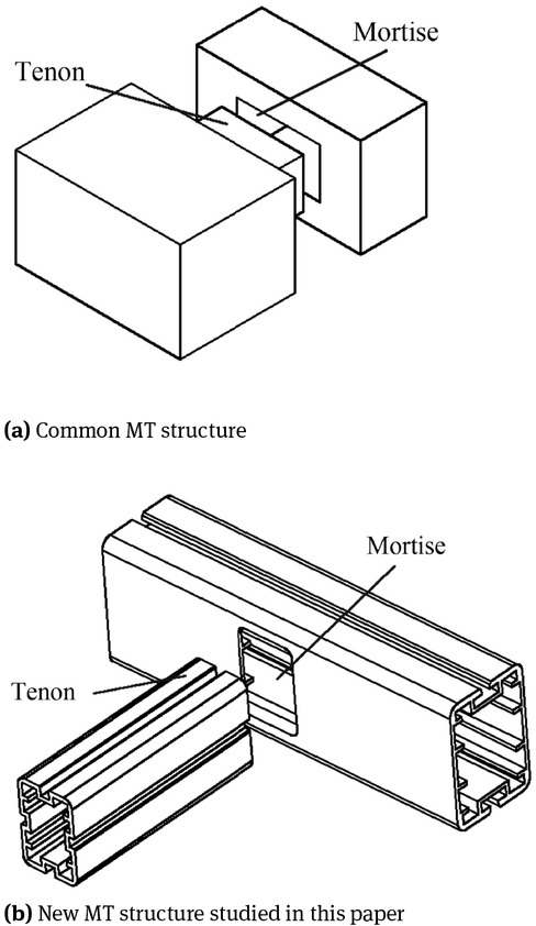
MT structure
In recent years, many researchers have done a lot of MT-T joints researched on failure modes, shear, flexural, force transmission mechanism, hysteretic rules and recovery force model [17, 18, 19, 20, 21, 22, 23]. The past studies mostly focus on MT-T joint qualitative performance. At present, researching on MT-T joint quantitative calculation method or model are relatively scarce. Such as C.C.Chen, et al. [24] had studied deformation mode and failure mechanism through the experiment. H Rohana et al. [25] and Judd et al. [26] analyzed MT-T joint deformation and internal force characteristics. And they carried out MT-T joint force transmission paths and failure modes under cyclic loading. Chun Q et al. [27] and Zhao H T et al. [28] obtained MT-T joint failure modes, hysteresis curves and in-plane rotational rigidity. Sandberg et al. [29] developed a method for predicting failure loads by the experiment. Ebrahimi G et al. [30] studied the influence of the geometric parameters to traditional MT-T joint structure through flexural behavior. Besides, they found that the mortise depth, tenon tongue and shoulder width have a greater impact than other geometric parameters on MT-T joint mechanical properties. X.S Song et al. [31] et al. proposed MT-T joint structural load transfer mechanism and bending M−θ relationship model through analysing chinese traditional MT building structure. XLi et al. [32] obtained the bending moment and relative rotation model, and the constitutive parameters of Kishi-ChenM−θ model for ITSD MT-T joints were calibrated by using statistical fitting methods. The above studies show that there are mainly several deficiencies on the MT-T joint research at home and abroad. One is that most researches are focus on qualitative characterization but are lack of quantitative calculation methods. The other is the uncertainty on wood properties let research difficult to form a unified methodology.
Aluminum alloy is an isotropic, stable and high qualities of metallic material. Its density is about one-third of steel [33, 34]. At present, the connection methods about aluminum alloy joint mostly adopt mechanical connection, welding connection and adhesive connection [35, 36, 37]. These connection methods all have some defects. Firstly, the mechanical connection needs perforation, which is not suitable for complex cross-section aluminum alloy [38]. Secondly, the aluminum alloy welding performance is poor, and the welding process is difficult [39, 41, 42, 43]. Thirdly, the bonding connection is still in the development stage, so, it cannot take into account the cost and performance [40, 44, 45]. Using hollow extruded aluminum alloy rather than timber composing MT-T joint structure can not only solve the defect of other aluminum alloy connection ways, but also solves the structural performance uncertainty caused by the timber performance [46, 47].
In this paper, for the above problems, a new aluminum alloy MT-T joint is put forward. As shown in Figure 1b. It is different from the traditional MT-T joint structure in metallic materials, geometry structure and connection process while relevant research was lack nowadays. Then, the following studies have been carried out. Firstly, the M − θ theoretical model with complex section is established. Secondly, the mechanical behavior and deformation mechanism on aluminum alloy MT-T joint are studied. Thirdly, the validity of the M − θ model is verified by experiments. Finally, mechanical behavior, failure mechanism and optimize design on MT-T joint are studied. All these researches about design and optimization provide theoretical and experimental support for vehicle lightweight.
For this text, mechanical models are obtained in Section 2. The experiments and simulations are done in Section 3. Comparisons to timber models are dealt with in Section 4. The summary and future perspectives are proposed in Section 5. Conflicts of interests and acknowledgement are dealt with in Section 6 and 7.
2 Mechanical modeling
DW joint has better mechanical properties compare to all other joints. The DW joint performance must be further analyzed during deformation process. Theoretical model on DW joint would be established in the following.
2.1 Material experiment
In experiment and simulation, the material is 6061-T6 aluminum alloy. Given its parameters, elastic modulus is E = 68 GPa, shear modulus is G = 14.6 GPa, yield strength is σ0.2 = 313 MPa and tensile strength is σb = 400 MPa.
The testing pieces are designed as shown in Figure 2. Two pieces of testing pieces are tested according to GB/T228-2010,which is Metal Material Tensile Test Method.

Dimension diagram of testing pieces for material properties
Where f0.1 is nominal yield strength. In other way, it is the stress at a residual strain of 0.1%. f0.2 is the nominal yield strength. In other way, it is the stress at a residual strain of 0.2%, fb is the tensile strength, E is the elastic modulus, ϵu is the ultimate strain.
They are tested by electronic universal testing machine. The test results are shown in Table 1.
Testing results of pieces standard material properties
| Testing | f0.1 | f0.2 | fb | E | ϵu /10−3 |
|---|---|---|---|---|---|
| pieces | /MPa | /MPa | /MPa | /GPa | |
| CX01 | 287.64 | 297.04 | 383.52 | 68.4 | 16.22 |
| CX02 | 304.56 | 315.84 | 404.2 | 68.7 | 15.11 |
The measured stress-strain curves of testing pieces are obtained, which is as shown in Figure 3. It is compared with the commonly used Ramberg-Osgood constitutive model curve [46], and the experimental data has a good agreement with the theory.
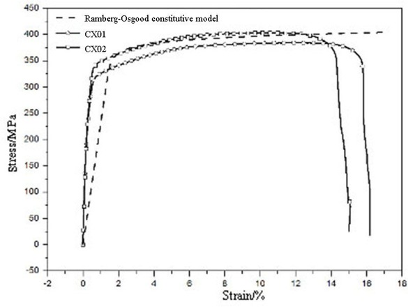
Comparison between experimental curves with Ramberg-Osgood
2.2 Basic assumptions
In order to simplify the calculations, several assumptions have been made before establishing the theoretical models, which are shown as following.
The tenon deformation on cross-beam is neglected, and it is assumed that the tenon only has a rigid motion within the mortise. Because the global displacement of every point in the tenon can be related to the rotation and the extruded displacement in this way.
MT is always in squeezing state under horizontal force, and the friction coefficients between the squeezing zones are constant and equal.
Compression stress is proportional to the squeezing deformation in the squeezing area while the joint is in its elastic period.
2.3 Geometric conditions
The joint material is aluminum alloy pipe squeezed, and tube sections are irregular. When MT produces a joint by interference fit. Different parts play different roles in deformation. Different geometric parts which participate in important mechanical properties need to be studied.
According to M − θ theoretical model, the squeezing area force is decided by squeezing stress and area. Both squeezing deformation and squeezing length need to be calculated in geometric conditions.
MT-T joint dimension diagram is shown in Figure 4. Under loading, the rotational center is the contact point of the MT, and it is expressed by O, the position of which we assume is always fixed.

MT-T joint dimension diagram
The T-joint deformation mechanisms are different under vertical and horizontal force. Deformation state diagram of MT-T joints under displacement load is shown as Figure 5. According to the structure deformation state and the geometric relations, the following equations could be obtained.

Deformation state diagram of MT-T joints under displacement load
The squeezing deformation satisfies the Eq. (1).
Where θ is the angular displacement between the ends of the joints, δa, δb, δc and δd are the squeezing deformation for area a, b, c and d, respectively, d2 and ds are the geometric parameters of joints, respectively. The squeezing length satisfies the equations.
La, Lb, Lc and Ld is the squeezing length for area a, b, c and d, respectively, dk, ds and h1 are the geometric parameters of joint members, respectively.
2.4 Equilibrium conditions
When an actuator is applying load at low speed, T joint is considered to be in a transient equilibrium state. Mechanical analysis of MT-T joints under horizontal reverse loading is shown as Figure 6.
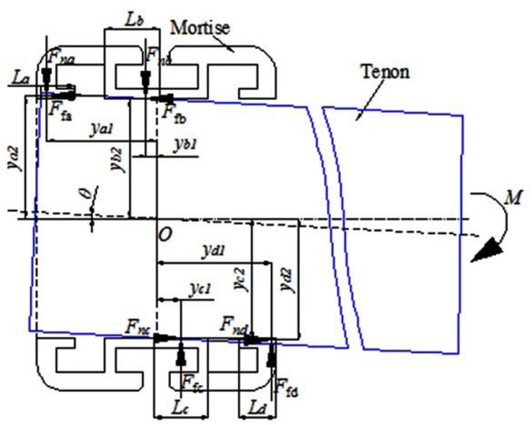
Mechanical analysis of MT-T joints under horizontal reverse loading
From Figure 6, based on torque equilibrium theory, the calculation equations are as follows.
2.5 Physical conditions
2.5.1 Elastic stage
The physical conditions are independent on the material stress-strain relationships instead of loading conditions. While the squeezing stress is less than the yield limit, the squeezing area is at the elastic stage.
When the joint is at the elastic stage, the acting point on the squeezing force is located in the squeezing center. The distance can be expressed as
In Eq. (6), ga1 (θ), gb1 (θ), gc1 (θ) and ga2 (θ) are functions related to θ.
According to Eq. (4), the following equation holds.
Where [δ] is the squeezing deformation matrix of squeezing area a, b, c and d, [ϒ] represents a parameter related to the elastic modulus of materials, which can be calculated from the following equation.
Where αi is regression parameter of joint force-displacement curves, E is material elastic modulus.
Under displacement loading, the following equation holds.
Where [K] is a coefficient matrix determined by joint structural parameters, which can be calculated form the following equation.
Where ws is tenon’s width, Li is squeezing length, because 6061-T6 aluminum alloy material is isotropic material, so we obtain the equation.
At this period, the frictional force belongs to the static frictional force produced by squeezing. And the static frictional force of the squeezing area can be expressed as
2.5.2 Elastoplastic stage
During elastoplastic stage, squeezing area is formed from elastic squeezing area and plastic squeezing area. When a, b, c and d squeezing area stress reach the ultimate compressive strength which is expressed as fc,90, we can get the equations following. Besides, squeezing area a is taken for example, others just are similar to a.
According to ultimate compressive strength of materials.
According to basic assumptions which is shown in Section 2.1.
During elastoplastic stage, squeezing resultant force application point locates in centroid of squeezing area. And distance expressed as xa could be deduced from application point to squeezing area edge.
Furthermore, distance from application point to rotation center expressed as ya1 is obtained.
Similarly, the joint moment in elastic-plastic stage could be get from following Eq. (22).
2.6 Results of the theoretical model
MATLAB software is used to obtain theM−θ data based on the MT-T joint theoretical model. The MT-T joint geometric and mechanical parameters are shown in Table 2.
Geometric and mechanical parameters of studied MT-T joint
| Parameter name | Value/mm |
|---|---|
| ws | 31 |
| t | 2 |
| dj | 5 |
| ds | 19.5 |
| dk | 7 |
| dw | 5.75 |
| e′ | 0.2 |
| e′′ | 0.2 |
| h1 | 45 |
| d2 | 45 |
| h3 | 44.6 |
| h4 | 45 |
As Figure 7 shows, the contribution which is squeezing area to bending moment determines the joint bearing capacity. Besides, squeezing area b plays a decisive role in this structure while squeezing area c hardly affects its mechanical properties. For area a, it can be divided into three stages. Firstly, the squeezing deformation begins to increase gradually,which leads contribution increase. Secondly, as the load decreases, the squeezing length and the contribution decreases. Thirdly, the squeezing areas are separated from each other. Through analysis, O position which affects mechanical properties is the most important factor. The main reasons are DW joint bearing capacity is better than that of BW joint and BW joint bearing capacity is better than that of CW joint.

Contribution of each squeezing area to the moment
2.7 Joint bilinear model
Considering comparisons between constitutive aluminum alloy model and theoretical MT-T joint model, we select bilinear model to describe it. Bilinear model contains elastic stage and elastoplastic stage. It is an ideal method for explaining aluminum alloy MT-T joint mechanical properties. Besides, in order to improve computational speed and efficiency on mechanical model for aluminium alloy MT-T joint, and facilitate its application in engineering, a bilinear model with contact point, yield point and limit point is constructed.
(A) Contact point
The contact point is the contact point between tenon and mortise. Because there are some errors in processing and manufacturing, there will be gaps between mortises and mortises after assembly. During stress process, squeezing area a first contact with the mortise. Defining rotation angle on squeezing area b and c when they overcome the gap and make tenon and mortise contact rigidly as θ0. From Eq. (1), squeezing deformation on the contact point can be obtained, and θ0 can be obtained by numerical solution. Then from Eq. (3), Eq. (4), Eq. (5), the moment M0 corresponding to θ0 can be obtained.
(B) Yield point
When squeezing area a just enters the plastic stage, it enters the yield point, the corresponding rotation angle is θy, then the following equation should be satisfied.
Where ka is the coefficient from Eq. (13). δa is the amount for squeezing deformation when squeezing area a reaches yield in Eq. (1). fc,90 is yield compressive strength, that is, 90% of tensile strength. By combining Eq. (1) and Eq. (23), θy can be obtained by numerical solution. The yield moment My corresponding to θy can be obtained by Eq. (3), (4) and (5).
(C) Limit point
Ignoring descending stage on curve in the later stage when loading, the maximum point strain for standard material property data is taken as its limit strain. When squeezing area a reaches the ultimate strain ϵu, the rotation angle for joint is θu. The ultimate squeezing deformation on squeezing area is δu. Then the following equation should be satisfied.
where β is regression coefficient in material performance test; δuis the squeezing deformation when squeezing area a reaches its limitation. By combining Eq. (1) and Eq. (24), the limit rotation angle θu can be obtained by numerical solution. The ultimate moment Mu corresponding to θu can be obtained by Eq. (3), (4) and (5).
Comparing joint bilinear mode curves with the test curves, seeing Figure 8.
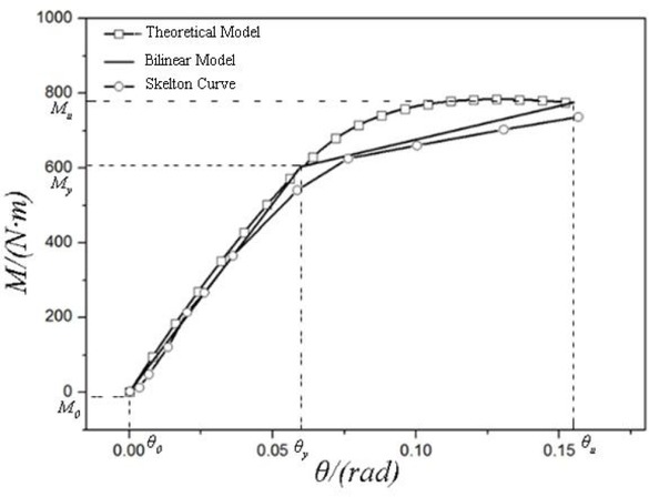
Comparison of experiment, theoretical model and simplified model curve
From Figure 8, the curves among bilinear model, joint skeleton drawn by the test and theoretical model are in good agreement, and the curves are in good agreement under each loading stage. Chen et al. [48] found that in the process of mechanical deformation on traditional wooden MT structure through a lot of researches, it can be divided into three stages: gap squeezing stage, elastic stage and plastic stage. Therefore, wooden MT joints are usually represented by three-stage linear model in practical engineering application. Xiong et al. [48] established bilinear line model, which is suitable for numerical calculation model performance analysis on aluminum alloy MT joint for electric vehicles. Aluminum alloy MT structure should adopt interference fit connection with larger interference. In initial loading period, there is no gap between MT fit surfaces, so there is no gap squeezing stage.
By analyzing curve’s error, the accuracy for double broken line model can be verified. Through calculation, the error is shown in Table 3.
Bilinear model and experimental error analysis
| Usage | θy /rad | My | θu /rad | Mu |
|---|---|---|---|---|
| Method | /N · m | /N · m | ||
| Joint bilinear | 0.06 | 603 | 0.155 | 775 |
| mode | ||||
| Experimental | 0.06 | 567 | 0.155 | 730 |
| data | ||||
| Error rate /% | – | 6.3 | – | 6.2 |
3 Experimental and simulation
According to the rule for calculating bending moment, the calculated bending moment is independent of beam length, and beam length is shown in Figure 9c. Specimen beam is 300 mm, and specimen column is 600 mm. In experiment and simulation, the material is 6061-T6 aluminum alloy. Its material properties are shown in Table 4. Besides, for aluminium alloy MT structure, while assembling, the interference assembly is adopted, the interference is 0.2mm, and the plastic hammer is used to hammer the assembly.

MT-T joint structure diagram
Material properties of experimental and simulation aluminum alloy
| Material properties | Symbol | Value |
|---|---|---|
| elastic modulus (GPa) | E | 68 |
| shear modulus (GPa) | G | 14.6 |
| yield strength (MPa) | σ0.2 | 313 |
| tensile strength (MPa) | σb | 400 |
In simulation, the methodology is Newton Iteration Method. The element type is hexahedron. constitutive equations are Ramberg-Osgood constitutive model. The mesh size is 2 mm, the internal connected part is 1 mm. boundaries are fixed the T-joint ends and simulated the experimental indenter with rigid body.
3.1 Loading program
In this study, the stiffness in T-joint area is analyzed under a bending load. To apply the bending load, a 50-kN Safety Testing Multi-Load system is used. As shown in Figure 10a, during the experiment, for one thing, the end face is fixed on the wall. For another, adjusting the actuator position is used for ensuring the horizontal or vertical direction in loading process. The loading process is controlled by displacement, which is arriving 60 mm at the speed of 0.1 mm/ s. Simulation loading schematic is shown as Figure 10b with the same conditions.

(a) Experimental schematic diagram; (b) simulation loading schematic diagram
3.2 Flexural behavior
As shown in Figure 11 and Figure 12a, for MT-T joint deformation, the experimental results can be fitted with the simulation results. To a certain extent, it can be shown that the FEM simulation model has accurately simulated the MT-T joint deformation process. In general, the failure mode is the squeezing and separation of the squeezing area, and finally part of squeezing enters the elastic-plastic state and loses the bearing capacity. In addition, according to the simulation model, it can be more convenient to analyzed the internal failure of the MT-T joint. By analyzing Figure 11, for the qualitative similarity on deformation mode and trend, we can get the failure of three squeezing area. For definite quantitative identical indication of its deformation size, the deformation error is analyzed in Table 4. And the theoretical model, the FEM simulation model and the bilinear model satisfy the engineering requirement accuracy.
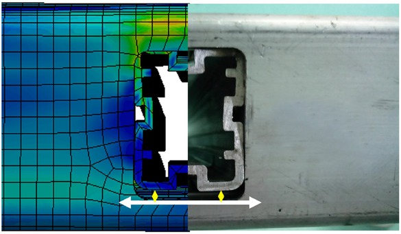
MT-T joints experimental deformation detail diagram
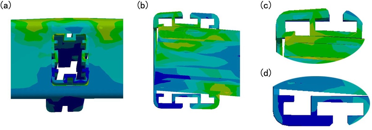
MT-T joints simulation deformation detail diagram
Besides, from Figure 12, it is found that the failure degree is basically proportional to the contribution of the squeezing area. Besides, with the O point as the center of rotation, the upper contact area of the MT structure is squeezing each other, the lower contact area is separated from each other. a squeezing area and d squeezing area deformation are the largest, then b squeezing area and c squeezing area deformation in the squeezing area are the smallest. It can be concluded that the larger the distance from the center of rotation, the greater the internal force, the greater the deformation.
3.3 Model verification
In order to verify the validity on the theoretical model, simulation model and proposed bilinear model, the experimental result curves are used for comparison. First of all, the four curves have the same changing trend. They are generally divided into two stages, one is elastic stage and the other is elastoplastic stage. Comparing the four curves, the theoretical model curve is almost the maximum value. This is because the tenon is regarded as rigid body in theoretical calculation, and its gap is neglected. The simulation model curve is almost the minimum in whole process. This is because in the FEM calculation, the MT is added to the parameters measured by the corresponding material parameter test, and the contact conditions can simulate the real scene to the maximum extent. However, there are errors in friction coefficient on the real aluminum alloy MT-T joint surface due to the standard aluminum alloy friction coefficient. The FEM simulation result is small. It is shown in Figure 13.
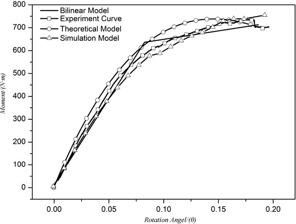
Comparison diagram between three models and experimental results
Necessarily, comparing to the three theoretical curves, the simulation model and the bilinear model which are compare with the experimental results, the errors are calculated at two characteristic points. As shown in Table 5. The theoretical model, the FEM simulation model and the bilinear model satisfy the engineering requirement accuracy of 10%. At the same time, the bilinear model will provide a theoretical basis for fast FEM calculation on future engineering calculations.
Error rate of model
| model | My | Error | Mu | Error |
|---|---|---|---|---|
| /(N · m) | rate | /(N · m) | rate | |
| Theoretical model | 630 | 6.9% | 707 | 0.4% |
| Simulation model | 556 | 5.1% | 739 | 4.1% |
| Bilinear model | 630 | 6.9% | 707 | 0.4% |
| Experiment | 586 | 710 |
4 Comparisons to timber model
Chen C. et al. [41] researched that each squeezing area will rotate at an angle to eliminate the gap between MT. Because trilinear model consists of compression stage, elastic stage and elastoplastic stage, it is used to describe the mechanical timber MT-T joint tendencies to safety. But aluminum alloy MT-T joints are different from timber MT-T joints because aluminum alloy is a kind of dense and isotropic metal. There is no gap between aluminum alloy MT at the beginning of loading. In general, the aluminum alloy MT-T joint deformation can be described in a two stage enough to satisfy engineering accuracy, and the errors are shown in Table 5.
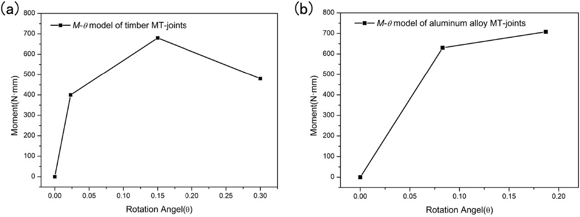
Comparison diagram between timber MT-T joint and aluminum alloy MT-T joint
5 Summary and future perspectives
Aluminum alloy MT structure is an effective lightweight designed structure for EVs. MT-T joints combine good flexural, torsional, seismic and processing characteristics. of MT structure and stability and high specific strength of aluminum alloy. In this paper, for MT-T joint, the problems such as theoretical calculation model, deformation behavior, and failure mode during loading process, were solved. The summaries are as follows:
Firstly, the geometric characteristics and balance relationship are analyzed, the relationship between bending M −θ is deduced and a theoretical calculation model for the whole joint deformation process is established. Besides, the M − θ relationship of the MT-T joint has an initial stage with elastic phase and then the rising trend slow. The M−θ relationship may be simplified into a bilinear model which consist of an elastic segment and elastoplastic segment.
Secondly, theoretical model shows that squeezing area shape, the squeezing area size and the MT contact surface size have significant influences on bearing capacity and initial stiffness. The influence about both squeezing area son initial stiffness and joint load-bearing capacity is more significant than that of friction area. Furthermore, on the premise that the joint has the same squeezing areas, the larger MT-T joint contact area is, the higher its bearing capacity and initial stiffness are.
Thirdly, MT-T joint main failure mode is plastic deformation caused by squeezed between squeezing areas. With the O point as the rotation center, the upper MT contact area is squeezing each other, the lower contact area is separated from each other, and a squeezing area deformation is the largest. Then both b squeezing area and c squeezing area deformation in squeezing area is the smallest. It can be concluded that the larger the distance from the rotation center is, the greater the internal force and the deformation are.
Fourthly, compared with traditional MT structure three-stage model and based on the theoretical model, simulation model and experimental analysis, the angular torque bilinear model on aluminium alloy MT structural joint is obtained.
Finally, the results about the structure and theoretical model on aluminium alloy MT structure obtained in this paper will promote aluminium alloy application in the lightweight of EVs.
In general, future work need to be more in-depth understood bonding property of MT structure and aluminum alloy, especially for other flexural behavior and mechanical model of MT-T joint. In fact, there are many factors affecting MT-T joint performance. The next step is to study modeling applicability of different metallic materials, different fit clearances and different load coupling conditions base on M − θ theoretical model.
Acknowledgement
This work is supported by the National Natural Science Foundation of China (Grant Nos. 51575205 and 51775565), and the major science and technology special projects in Guangdong (Grant No.2016B010118001), and the Fundamental Research Funds for the Central Universities (Grant No. 18lgpy83).
List of Abbreviations
- MT
Mortise-and-tenon
- AW
Welded joint by tungsten inert gas
- MT-T joint(s)
Mortise-and-tenon T joint(s)
- BW
Half-tenon blind-hole joint
- EVs
Electric vehicles
- CW
Whole tenon blind hole joint
- FEM
Finite element method
- DW
Tenon fully inserted joint
- M-θ
Moment and rotation angle
List of symbols
- t
Stiffener thickness
- Ffa, Ffb, Ffc, Ffd
Frictional force acted in a, b or c squeezing area
- h1
Length of tenon
- ya1, yb1, yc1, yd1
Distance from squeezing force action point to the rotation center in a, b or c squeezing area
- h2
Width of stiffener for mortise
- ya2, yb2, yc2, yd2
Distance from friction action point to the rotation center in a, b or c squeezing area
- d2
Width of mortise
- cb2, cc2
Constants dependent only on the geometric parameters
- dj
Stiffener height
- [F]
Force of the squeezing area
- ds
Width of mortise-and-tenon fitting surface
- [σ]
Squeezing stress
- dk
Distance between stiffener top face and mortise top face
- [A]
Area
- dw
Distance between stiffener top face and mortise-and-tenon outer face
Conflict of Interest
Conflict of Interests: The authors declare that there is no conflict of interests regarding the publication of this article.
References
[1] Zhang X., Liang Y., Yu E. et al., Review of electric vehicle policies in China: Content summary and effect analysis, Renew. Sust. Energ. Rev., 2017, 70, 698-714.10.1016/j.rser.2016.11.250Search in Google Scholar
[2] Gong X., Xie C., Zou Y. et al., Performance and stability of supercapacitor modules based on porous carbon electrodes in hybrid powertrain, J. Wuhan. Univ. Technol. Sci. Ed., 2014, 29(6), 11411146.10.1007/s11595-014-1056-7Search in Google Scholar
[3] Hu X., Cao D., Egardt B., Condition Monitoring in Advanced Battery Management Systems: Moving Horizon Estimation Using a Reduced Electrochemical Model, IEEE/ASME. T. Mech, 2018, 23(1), 167-178.10.1109/TMECH.2017.2675920Search in Google Scholar
[4] Zou C., Hu X., Dey S. et al., Nonlinear Fractional-Order Estimator with Guaranteed Robustness and Stability for Lithium-Ion Batteries, IEEE T. Ind. Electron, 2018, 65(7), 5951-5961.10.1109/TIE.2017.2782691Search in Google Scholar
[5] Egede P., Concept for the Environmental Assessment of Lightweight Electric Vehicles, Envir. Assess. Lightw. Electr. Vehic. Springer, 2016, 2, 59-91.10.1007/978-3-319-40277-2_4Search in Google Scholar
[6] Heim K., Vinod-Kumar G.S., García-Moreno F. et al., Stability of various particle-stabilised aluminium alloys foams made by gas injection, J. Mater. Sci., 2017, 52(11), 6401-6414.10.1007/s10853-017-0874-3Search in Google Scholar
[7] Guanetti J., Formentin S., Savaresi S. M., Energy Management System for an Electric Vehicle with a Rental Range Extender: A Least Costly Approach, IEEE T. Intell. Transp., 2016, 17(11), 3022-3034.10.1109/TITS.2016.2529962Search in Google Scholar
[8] Qi Y., Lapovok R., Estrin Y., Microstructure and electrical conductivity of aluminium/steel bimetallic rods processed by severe plastic deformation, J. Mater. Sci., 2016, 51(14), 6860-6875.10.1007/s10853-016-9973-9Search in Google Scholar
[9] Harada M., Hayashi Y., Hayashi T. et al., Effect of moisture content of members on mechanical properties of timber joints, J. Wood Sci., 2005, 51(3), 282-285.10.1007/s10086-004-0656-9Search in Google Scholar
[10] Yue Z., Traditional chinese wood structure joints with an experiment considering regional differences, Int. J. Archit. Herit., 2014, 8(2), 224-246.10.1080/15583058.2012.688179Search in Google Scholar
[11] Li L.X., Xu Z.H., Ma M.C. et al., Present and Future Research of Mortise and Tenon Joint in Timber Structure, AMM, 2016, 851, 649-654.10.4028/www.scientific.net/AMM.851.649Search in Google Scholar
[12] Xie Q.F., Du B., Xiang W. et al., Experimental study on seismic behavior and size effect of dovetail mortise-tenon joints of ancient timber buildings, J. Build. Struct., 2015, 36(03), 112-20.Search in Google Scholar
[13] Akcay H., Eckelman C., Haviarova E., Withdrawal, shear, and bending moment capacities of round mortise and tenon timber framing joints, Forest. Prod. J., 2005, 55(6), 60-72.Search in Google Scholar
[14] Feio A.O., Lourenço P.B., Machado J.S., Capacity of a traditional timber mortise and tenon joint, 6th Inter. Confer. Struct. Analys. Histor. Constr., 2008, 47(1-2), 213-225.10.1617/s11527-013-0056-ySearch in Google Scholar
[15] Chen C.C., Qiu H.X., Bao Y.N., Study on the flexural mechanical model of straight mortise-tenon joints in the base of melon-column, J. Hunan Univ., 2015, 2015(3), 50-56.Search in Google Scholar
[16] Qing C., Pan J., Dong Y., Mechanical Properties of Tou Mortisetenon Joints of the Traditional Timber Buildings in the South Yangtze River Regions, J. Southwest Jiaotong Univ., 2016. 32(4), 457-463.Search in Google Scholar
[17] Girhammar U.A., Jacquier N., Bo K., Stiffness model for inclined screws in shear-tension mode in timber-to-timber joints, Eng. Struct., 2017, 136(1), 580-595.10.1016/j.engstruct.2017.01.022Search in Google Scholar
[18] Kang K., Qiao G., Chen J. et al., The influence of gap between tenon and mortise on the bearing behavior of the dovetail joints in ancient timber structure by finite element analysis, CS, 2016, 11(1), 38-42.Search in Google Scholar
[19] Izzi M., Rinaldin G., Polastri A. et al., A hysteresis model for timber joints with dowel-type fasteners, Eng. Struct., 2018, 157(15), 170-178.10.1016/j.engstruct.2017.12.011Search in Google Scholar
[20] Lacourt P.A., Crisafulli F.J., Mirasso A.E., Finite element modelling of hysteresis, degradation and failure of dowel type timber joints, Eng. Struct., 2016, 123(15), 89-96.10.1016/j.engstruct.2016.05.034Search in Google Scholar
[21] Xie Q., Wang L., Zheng P. et al., Rotational behavior of degraded traditional mortise-tenon joints: experimental tests and hysteretic model, Int. J. Archit. Herit., 2017, 12(17), 125-136.10.1080/15583058.2017.1390629Search in Google Scholar
[22] Ogawa K., Sasaki Y., Yamasaki M., Theoretical estimation of the mechanical performance of traditional mortise–tenon joint involving a gap, J. Wood. Sci., 2016, 62(3), 242-250.10.1007/s10086-016-1544-9Search in Google Scholar
[23] Song X., Jingyu S.U., Guo X. et al., A review of research on seismic performance of mortise-tenon joints in chinese ancient timber buildings, J. Earthq. Eng., 2014, 30(1), 12-22.Search in Google Scholar
[24] Chen C.C., Qiu H. X., Xu M.G., Experimental study on flexural behavior of typical mortise-tenon joints, AMM, 2014, 578-579, 160-163.10.4028/www.scientific.net/AMM.578-579.160Search in Google Scholar
[25] Rohana H., Azmi I., Zakiah A., Shear and bending performance of mortise and tenon connection fastened with dowel, J. Trop. For. Sci., 2010, 22(4), 425-432.Search in Google Scholar
[26] Judd J.P., Fonseca F.S., Walker C.R. et al., Tensile strength of varied-angle mortise and tenon connections in timber frames, J. Struct. Eng., 2012, 138(5), 636-644.10.1061/(ASCE)ST.1943-541X.0000468Search in Google Scholar
[27] Chun Q., Meng Z., Han Y., Research on mechanical properties of main joints of chinese traditional timber buildings with the type of post-and-lintel construction., Int. J. Archit. Herit., 2016, 11(2), 247-260.10.1080/15583058.2016.1204487Search in Google Scholar
[28] Zhao H.T., Zhang H.Y., Xue J.Y. et al., The stiffiness analysis on the characteristic of mortise-tenon joint in historical timber buildings, XAUAT, 2009, 41(4), 450-454.Search in Google Scholar
[29] Sandberg L.B., Bulleit. W.M., Reid E.H., Strength and stiffness of oak pegs in traditional timber-frame joints, J. Struct. Eng., 2000, 126(6), 717-723.10.1061/(ASCE)0733-9445(2000)126:6(717)Search in Google Scholar
[30] Derikvand M., Ebrahimi G., Eckelman C. A., Bending moment capacity of mortise and loose-tenon joints, Wood Fiber, 2014, 46(2), 159-166.Search in Google Scholar
[31] Song X.S., Su J.Y., Guo X.D., Research progress on mechanical properties of chinese ancient mortise-tenon joints, AMM, 2013, 405-408, 1067-1072.10.4028/www.scientific.net/AMM.405-408.1067Search in Google Scholar
[32] Li X., Zhao J., Ma G. et al., Experimental study on the traditional timber mortise-tenon joints, Adv. Struct. Eng., 2015, 18(12), 2089-2102.10.1260/1369-4332.18.12.2089Search in Google Scholar
[33] Shi Y.J., Cheng M., Wang Y.Q., Application and study of aluminum alloy in building structures, Build. Sci, 2005, 21(6), 7-11.10.1016/S1007-0214(06)70247-4Search in Google Scholar
[34] Zheng H., Zhao X., Lightweight automobile and application of aluminum alloys in modern automobile production, Forg. Stamp. Tech., 2016, 42(2), 1-6.Search in Google Scholar
[35] Cheng M., Shi Y.J., Wang Y.Q., Connection of aluminum members and design method, Build. Sci., 2006, 22(3), 85-89.Search in Google Scholar
[36] Shi-Yun H.E., Fang G.R., Research and Application of Aluminum Alloy Pipe Cartridge Connection Construction Technology, Constr. Design Proj., 2017, 18, 144-150.Search in Google Scholar
[37] Prapas M., Jennarong N., Woraphot P., Effect of post-weld heat treatment on microstructure and mechanical properties of friction stir welded SSM7075 aluminium alloy, J. Wuhan. Univ. Technol. Sci. Ed., 2017, 32(6), 1420-1425.10.1007/s11595-017-1763-ySearch in Google Scholar
[38] Xiao S.N., Jia Y., Strength analysis of rivet and bolt joint structure in aluminum alloy car body of high-speed train, Electric. Locomot. Mass. Trans. Vehic., 2004, 27(5), 16-31.Search in Google Scholar
[39] Paik J.K., Mechanical properties of friction stir welded aluminum alloys 5083 and 5383, Int. J. Nav. Arch. Ocean, 2009, 1(1), 39-49.10.2478/IJNAOE-2013-0005Search in Google Scholar
[40] Ronghui Z., Zhaocheng H. et al., Study on self-tuning tyre friction control for developing main-servo loop integrated chassis control system, IEEE Access, 2017, 5, 6649-6660.10.1109/ACCESS.2017.2669263Search in Google Scholar
[41] Lázaro J., Solórzano E., Rodríguez Pérez M.A. et al., Pore connectivity of aluminium foams: effect of production parameters, J. Mater. Sci., 2015, 50(8), 3149-3163.10.1007/s10853-015-8876-5Search in Google Scholar
[42] Qiang L., Jinsha W., Xinshen H., Tianming W., Zhijian Z., Qing L., In-plane and out-of-plane bending responses of aluminum mortise-tenon joints in lightweight electric vehicle inspired by timber structures, Thin-Walled Struct., 2018, 127, 169-179.10.1016/j.tws.2018.01.033Search in Google Scholar
[43] Sun X.J., Zhang H., Meng W.J., Zhang R.H., Li K.L., Peng T., Primary resonance analysis and vibration suppression for the harmonically excited nonlinear suspension system using a pair of symmetric viscoelastic buffers, Nonlin. Dyn, 2018, 94, 1243-1265.10.1007/s11071-018-4421-9Search in Google Scholar
[44] Baldan A., Adhesion phenomena in bonded joints, Int. J. Adhes. Adhes, 2012, 38(4), 95-116.10.1016/j.ijadhadh.2012.04.007Search in Google Scholar
[45] Huiyuan X., Xionglai Z., Ronghui Z., Energy Recovery Strategy Numerical Simulation for Dual Axle Drive Pure Electric Vehicle Based on Motor Loss Model and Big Data Calculation, Complexity, 2018, 4071743, 14.10.1155/2018/4071743Search in Google Scholar
[46] Xiong H., Tan Z., Zhang R. et al., Numerical calculation model performance analysis for aluminum alloy mortise-and-tenon structural joints used in electric vehicles, Compos. Part. B-Eng., 2019, 161, 77-86.10.1016/j.compositesb.2018.10.034Search in Google Scholar
[47] Huiyuan X., Minghui Z., Ronghui Z. et al., A new synchronous control method for dual motor electric vehicle based on cognitive-inspired and intelligent interaction, Future Generat. Comp. Syst., 2019, 94, 536-548.10.1016/j.future.2018.12.007Search in Google Scholar
[48] Chen C.C., Qiu H., Lu Y., Flexural behaviour of timber dovetail mortise–tenon joints, Constr. Build. Mater., 2016, 112, 366-377.10.1016/j.conbuildmat.2016.02.074Search in Google Scholar
© 2019 H. Xiong et al., published by De Gruyter
This work is licensed under the Creative Commons Attribution 4.0 Public License.
Articles in the same Issue
- Research Articles
- Investigation of rare earth upconversion fluorescent nanoparticles in biomedical field
- Carbon Nanotubes Coated Paper as Current Collectors for Secondary Li-ion Batteries
- Insight into the working wavelength of hotspot effects generated by popular nanostructures
- Novel Lead-free biocompatible piezoelectric Hydroxyapatite (HA) – BCZT (Ba0.85Ca0.15Zr0.1Ti0.9O3) nanocrystal composites for bone regeneration
- Effect of defects on the motion of carbon nanotube thermal actuator
- Dynamic mechanical behavior of nano-ZnO reinforced dental composite
- Fabrication of Ag Np-coated wetlace nonwoven fabric based on amino-terminated hyperbranched polymer
- Fractal analysis of pore structures in graphene oxide-carbon nanotube based cementitious pastes under different ultrasonication
- Effect of PVA fiber on durability of cementitious composite containing nano-SiO2
- Cr effects on the electrical contact properties of the Al2O3-Cu/15W composites
- Experimental evaluation of self-expandable metallic tracheobronchial stents
- Experimental study on the existence of nano-scale pores and the evolution of organic matter in organic-rich shale
- Mechanical characterizations of braided composite stents made of helical polyethylene terephthalate strips and NiTi wires
- Mechanical properties of boron nitride sheet with randomly distributed vacancy defects
- Fabrication, mechanical properties and failure mechanism of random and aligned nanofiber membrane with different parameters
- Micro- structure and rheological properties of graphene oxide rubber asphalt
- First-principles calculations of mechanical and thermodynamic properties of tungsten-based alloy
- Adsorption performance of hydrophobic/hydrophilic silica aerogel for low concentration organic pollutant in aqueous solution
- Preparation of spherical aminopropyl-functionalized MCM-41 and its application in removal of Pb(II) ion from aqueous solution
- Electrical conductivity anisotropy of copper matrix composites reinforced with SiC whiskers
- Miniature on-fiber extrinsic Fabry-Perot interferometric vibration sensors based on micro-cantilever beam
- Electric-field assisted growth and mechanical bactericidal performance of ZnO nanoarrays with gradient morphologies
- Flexural behavior and mechanical model of aluminum alloy mortise-and-tenon T-joints for electric vehicle
- Synthesis of nano zirconium oxide and its application in dentistry
- Surface modification of nano-sized carbon black for reinforcement of rubber
- Temperature-dependent negative Poisson’s ratio of monolayer graphene: Prediction from molecular dynamics simulations
- Finite element nonlinear transient modelling of carbon nanotubes reinforced fiber/polymer composite spherical shells with a cutout
- Preparation of low-permittivity K2O–B2O3–SiO2–Al2O3 composites without the addition of glass
- Large amplitude vibration of doubly curved FG-GRC laminated panels in thermal environments
- Enhanced flexural properties of aramid fiber/epoxy composites by graphene oxide
- Correlation between electrochemical performance degradation and catalyst structural parameters on polymer electrolyte membrane fuel cell
- Materials characterization of advanced fillers for composites engineering applications
- Humic acid assisted stabilization of dispersed single-walled carbon nanotubes in cementitious composites
- Test on axial compression performance of nano-silica concrete-filled angle steel reinforced GFRP tubular column
- Multi-scale modeling of the lamellar unit of arterial media
- The multiscale enhancement of mechanical properties of 3D MWK composites via poly(oxypropylene) diamines and GO nanoparticles
- Mechanical properties of circular nano-silica concrete filled stainless steel tube stub columns after being exposed to freezing and thawing
- Arc erosion behavior of TiB2/Cu composites with single-scale and dual-scale TiB2 particles
- Yb3+-containing chitosan hydrogels induce B-16 melanoma cell anoikis via a Fak-dependent pathway
- Template-free synthesis of Se-nanorods-rGO nanocomposite for application in supercapacitors
- Effect of graphene oxide on chloride penetration resistance of recycled concrete
- Bending resistance of PVA fiber reinforced cementitious composites containing nano-SiO2
- Review Articles
- Recent development of Supercapacitor Electrode Based on Carbon Materials
- Mechanical contribution of vascular smooth muscle cells in the tunica media of artery
- Applications of polymer-based nanoparticles in vaccine field
- Toxicity of metallic nanoparticles in the central nervous system
- Parameter control and concentration analysis of graphene colloids prepared by electric spark discharge method
- A critique on multi-jet electrospinning: State of the art and future outlook
- Electrospun cellulose acetate nanofibers and Au@AgNPs for antimicrobial activity - A mini review
- Recent progress in supercapacitors based on the advanced carbon electrodes
- Recent progress in shape memory polymer composites: methods, properties, applications and prospects
- In situ capabilities of Small Angle X-ray Scattering
- Review of nano-phase effects in high strength and conductivity copper alloys
- Progress and challenges in p-type oxide-based thin film transistors
- Advanced materials for flexible solar cell applications
- Phenylboronic acid-decorated polymeric nanomaterials for advanced bio-application
- The effect of nano-SiO2 on concrete properties: a review
- A brief review for fluorinated carbon: synthesis, properties and applications
- A review on the mechanical properties for thin film and block structure characterised by using nanoscratch test
- Cotton fibres functionalized with plasmonic nanoparticles to promote the destruction of harmful molecules: an overview