A review on the mechanical properties for thin film and block structure characterised by using nanoscratch test
-
 ,
,

Abstract
The nanoscratch test has been identified as one of the important tools for evaluating the mechanical and tribological properties of materials. This paper reviews the current researches on the nanoscratch test using to characterise the mechanical properties of three typical materials, including thin film, polymer composite and concrete, from the perspectives of the Berkovich indenter, parameter selection, mode selection, and analysis of resulting data. In addition, to provide a deep understanding on the test from different magnitude, a comparison between the microscratch test and nanoscratch test on the evaluation of tribological performance is also provided in this paper. The characterisation by nanoscratch test of two structural samples, in terms of layered film structures (thin film and coating sample) and single layer block structure (polymer composite sample and concrete samples) are also described in this paper, which aims to provides a deep understand on the evaluation the adhesion, tribological and interfacial properties of the typical materials samples by nanoscratch test. Finally, the coefficient of friction and critical load are discussed, which are two important parameters in tribological properties and adhesion properties.
1 Introduction
It has been widely accepted that research on a microscopic scale plays an important role in the field of materials research. Nanoindentation test and nanoscratch test has been identified as two common methods for evaluating the micromechanical properties of materials. As shown in Figure 1(a), the nanoindentation test can generate the load-displacement data by pressing the surface of material with an indenter. The hardness and elastic modulus can be determined from load-displacement data by methods developed by Oliver and Pharr [1]. Moreover, other mechanical properties, i.e. the contact stiffness [2] and the fracture toughness [3, 4], can be also obtained by analysis load-displacement curves and contact models, where the fracture toughness is defined as the energy density required to propagate defects already present in the film to fracture [4]. Generally, how to distinguishing fracture toughness and inherent total toughness becomes an important issue when studying single crystals. To compare the intrinsic toughness of different single crystal phases, nanoindentation has to be set at constant penetration depths, which suggests that the material with a larger toughness should fracture at a deeper diamond wedge penetration [5, 6]. Nanoscratch test (Figure 1(b)) is accomplished by applying a normal load in a controlled mode while measuring the force required moving the tip laterally across the sample [7]. The information including scratch depth, friction coefficient, and lateral force change of the material can be also offered by the nanoscratch test, which can further links to the adhesion properties and tribological properties of the material [8, 9]. Compared to the nanoindentation test, more reliable and complete interface mechanical properties of the materials can be characterised due to the continuous real-time point information generated from the nanoscratch test [10].
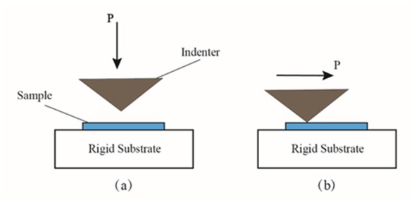
(a) schematic diagram of nanoindentation test process; (b) schematic diagram of the nanoscratch test process
Although only a few decades of development, the extensive researches conducted by the nanoindentation and the nanoscratch make them become the two most important techniques for studying the nanoscale mechanical properties of materials. Their applications cover various engineering fields, including materials engineering (e.g. self-healing microcapsules [11]), bioengineering and medical engineering (e.g. hair, bones, cells [12, 13, 14, 15, 16, 17]), construction engineering (e.g. cement composite [18, 19, 20, 21, 22]), etc. Regardless of the application fields, the test samples include different configurations, in which layered structures such as thin films [23, 24, 25, 26] and coatings [27, 28, 29] are the most widely studied structures; in addition, for investigating the block materials such as nanocomposites, non-film type samples are commonly used [30, 31, 32]. In general, nanoindentation testing is mostly used to determine the hardness and elastic modulus of materials, while nanoscratch testing is normally employed to evaluate the tribological properties, adhesion properties and interfacial properties of materials. Therefore, more and more researchers use both nanoindentation and nanoscratch in combination to gain a sophisticated understanding of the nanomechanical properties of materials as reported by Tsui et al. [33], who used the combination of the nanoindentation and the nanoscratch to determine the mechanical properties of several carbon thin films, such as elastic modulus, hardness and wear resistance, and finally select the hard carbon coating with the best mechanical properties.
A summary description of the nanoscratch test reported by other researchers is presented as follows: Valli et al. [34] reported the development of a nanoscratch test method for adhesion evaluation in the study of adhesion of TiN coatings by focusing on the correlation between friction and coating failure. Randall et al. [35] outlined the reliability of the nanoscratch test for studying the mechanical properties of thin film systems, by which the authors first introduced the scratch pattern and experimental parameters of the nanoscratch instrument, and then listed the nanoscratch test of three thin film systems to verify the adapability of the nanoscratch test in characterising the mechanical properties of the film systems. Later in 2013, Beake et al. [10] summarised the recent progress in nanoscratch testing applied in different engineering fields, which covered the types of nanoscratch testing and the influencing factors of experimental results. With the development in recent years, research materials for nanoscratch testing have not been limited to films and coatings. However, till present, there have been few review papers regarding on how to use the nanoscratch test to study the mechanical properties of materials, regardless of the film and coating materials, or other materials. This paper is focused on how to use the nanoscratch test to study the mechanical properties of two different structures materials, including tribological properties, adhesion properties and interface mechanical properties.
In this paper, a systematic description of the nanoscratch test used for the materials with two typical structures, namely thin film and single-layer block structure is presented. The single layer block structure described herein refers to a composite sample of a non-thin film structure, including a polymer composite material and a cement composite material. A detailed summary of the nanoscratch test, which covers the commonly used Berkovich indenter, the parameter settings and the analysis of result data including the parameters and data concepts, is firstly introduced. Then, the microscratch test is introduced, and the difference between the microscratch test and the nanoscratch test on different orders of magnitude is then compared. Following that, the nanoscratch test employed to characterise the nanomechanical properties (adhesion properties, tribological properties and interface mechanical properties) of two typical structural samples, in terms of the layered thin film structure and the single layer block structure, are described. Finally, two important results generated from most nanoscratch tests, in terms of friction coefficient and critical load, are discussed.
2 Basic settings and parameters
This section describes the basic settings and parameters of the nanoscratch test, including the commonly used Berkovich indenter, basic test parameter settings and main result data.
2.1 Berkovich indenter
Berkovich indenter is one of the most commonly used indenters of nanoscratch test, which is a three-sided pyramid indenter with three different orientations, the edge-forward, the face-forward and the side-forward as shown in Figure 2 [36]. It should be noticed that the results are significantly affected by the orientation of the indenter. When determining the tribological properties of single crystal silicon, Youn et al. [38] studied the effect of experimental conditions on the coefficient of friction (COF) of single-crystal silicon by nanoscratch test. The result shows that the three different orientations of Berkovich indenter have a significant effect on COF, ranging from 0.16 and 0.38. Moreover, numerical simulation was also conducted to study the effect of indenter orientation on the COF. Mulliah et al. [39] used Parallel molecular dynamics to simulate the effect of three different indenter orientations on the COF, and reported that the COF varies from ~0.37 to ~0.57 depending on the orientation of the indenter. Chamani and Ayatollahi [37] established a finite element analysis model to calculate the COF of Berkovich indenter in different orientations, and verified the results by experiments. All their research confirmed that the COF is highly depended on the orientation of the indenter.
![Figure 2 Schematic representation of the Berkovich indenter: different tip orientations, including edge-forward, side-forward and face-forward [37]](/document/doi/10.1515/ntrev-2019-0055/asset/graphic/j_ntrev-2019-0055_fig_002.jpg)
Schematic representation of the Berkovich indenter: different tip orientations, including edge-forward, side-forward and face-forward [37]
2.2 Test parameter setting
The parameter setting mainly includes the scratch length, the normal load, and the scratch velocity. Besides, an important step of nanoscratch test is the choice of scratch pattern. However, regardless of the scratch patterns, a three-stage process has to be conducted.
Pre-scan: Pre-scanning is the scanning of the sample surface with a load (usually 0.5μN) which is low enough to prevent damage to the sample surface before the scratch begins. This process delivers the initial surface information of the sample, such as the location of the scratch, the surface roughness of the sample.
Scratch: The scratch stage refers to the process in which the indenter scratches along the sample surface and leaves a scratch on the surface of the sample. The process of which are normally controlled by selecting three parameters, i.e. normal force, scratch length, and scratch velocity. In the scratch stage, depending on the normal force loading mode, it can be divided into the constant load mode and the ramped load mode. According to the load data provided by the nanoindenter G200, the maximum load can reach 500mN, but according to the experimental operator, the maximum load setting usually does not exceed 20mN, because excessive load might damage the instrument. Constant load mode is normally used to study the wear resistance and COF of materials, while ramped load mode is often used to evaluate the interlayer properties of the coating-substrate system. The selection the loading mode can also depended on the nature of the materials, for example, for the non-layered materials (polymer, etc.), the constant load is preferred to study the tribological properties, however, for the materials with layered structure, the ramped load is mainly applied to study the mechanical properties of the interface between different layers. Moreover, the combination of two loading methods are often employed during the characterisation to obtain extra information. Wei et al. [40] used both constant load and ramped load modes to determine the mechanical properties of Cr compound thin films (Cr, Cr2N and CrN). The experimental results showed that the Cr2N film was the most wear-resistant and effective protective coating in the tribological properties, but the adhesion was the lowest. Their research revealed that the nanoscratch test could offer the guidance for protective coating selection.
In the parameter setting of the scratch mode, double nanoscratch or multiple repeated nanoscratch by adjusting the number of scratch cycles are usually conducted by many researchers. Previous studies have shown that the wear and deformation mechanisms of materials in scratches are not only controlled by a single abrasive, but also by the interaction between multiple abrasives [41, 42]. Chen et al. [43] conducted single nanoscratch, double nanoscratch and multiple nanoscratch tests on Lu2O3 transparent ceramics to study the removal and deformation mechanism of the materials. After considering the elastic recovery effect, the theoretical models of the penetration depth in all single scratch, double nanoscratch and multiple nanoscratch tests were also established. The results showed that the adjacent scratch distance between the double nanoscratches influenced the elastic recovery rate as that elastic recovery increases with the increase of distance and eventually stabilizes. This result was close to the theoretical model prediction, thus verifying the reliability of the theoretical model. Moreover, there is also a commonly used multiple repeated nanoscratch called nanowear, which was first described by Bull and Rickerby [44] as a constant load, unidirectional multipass scratch testing, has been shown to be an effective low cycle fatigue test. The process is shown in Figure 3. Nanowear tests are often employed to study the tribological properties of materials. Through nanowear, researchers can better understand the surface and interface phenomena from the nanoscale level. Beake et al. [45] studied the wear resistance of uniaxially and biaxially drawn poly (ethylene terephthalate) films (PET films) by using multi-pass nanoscratch test combined with both nanoindentation test and nanoscratch test together to reveal that the different treatment methods of PET film lead to significant differences in mechanical properties. The results of the nanoscratch test showed that the biaxial film exhibited better wear resistance. Moreover, by combining with the hardness and elasticity modulus measurement, it is also reported that the wear resistance of the film was related to the ratio of hardness to modulus. Lee et al. [46] used the nanowear test to study the mechanical properties of CrN films prepared by two different film deposition methods not only by combining the nanoindentation test, but also by combining atomic force microscopy with ramped loading nanoscratch experiment. The research is aimed to study the comparison of different preparation techniques on characterisation of the mechanical properties of CrN films from surface morphology, roughness, hardness, elastic modulus, COF and wear resistance. The two different thin film deposition methods were reactive radio frequency magnetron sputtering (RF-CrN film) and cathodic arc plasma deposition (CAPD-CrN film), respectively. The results show that RF-CrN film is superior to CAPD-CrN film in nanomechanical properties such as hardness, COF and wear resistance.
Post-scan: The post-scan is similar to the pre-scan, scanning the scratched area with a sufficiently low load (usually 0.5μN) to obtain the sample surface information after the scratch.
For nanoscratch test, since the data generated from above three stages are related to each other, the data from each stage are usually placed together for comparison. For example, because it is very difficult to prepare the specimen with an absolutely smooth surface, the parallel analysis with the scratch and the pre-scan could eliminated the error caused due to the unsmooth surface. The scratch curve is expressed as the instantaneous scratch depth, and the post-scan curve is identified as the residual scratch depth, so the difference between the two curves can be recognised as the degree of elastic recovery of the material. Figure 4 shows an example of the nanoscratch test of copper by Xu et al. [47], and the image after the scratch of the sample is added to make the result more intuitive.
![Figure 3 Diagram of constant load, unidirectional multipass scratch testing (nanowear) [10]](/document/doi/10.1515/ntrev-2019-0055/asset/graphic/j_ntrev-2019-0055_fig_003.jpg)
Diagram of constant load, unidirectional multipass scratch testing (nanowear) [10]
![Figure 4 Nanoscratch test results on copper surfaces [47]: (a) Schematic diagram of the ramped load; (b) schematic diagram of the constant load](/document/doi/10.1515/ntrev-2019-0055/asset/graphic/j_ntrev-2019-0055_fig_004.jpg)
Nanoscratch test results on copper surfaces [47]: (a) Schematic diagram of the ramped load; (b) schematic diagram of the constant load
2.3 Analysis of the results
The output of the nanoscratch test includes the scratch depth curve and the normal force change. If the instrument is equipped with a lateral force sensor, the change in lateral force and the COF during the scratching process can also be obtained. The COF, coefficient of friction, is defined as ratio between the lateral force and the normal force in the scratch test. On one hand, these results directly obtained from the test are referred as intuitive data. On the other hand, extra information can also be easily generated by analysing the intuitive data. For example, for thin film or multilayer structure samples, the ramped load mode is used to obtain the critical load (Lc) of interlayer failure, which is defined as the load value under a gradually increasing load, excess of which the coating is significantly damaged [48]. The cracking or delamination of the film and the coating can be identified as a sudden increase in the COF, so that the critical load can be obtained by analysing the change in the COF [49, 50]. Under a constant load, by subtracting the depth of the pre-scan stage from the scratch depth in the scratch stage, the penetration depth, and the different phases in the material can be determined according to the change of the penetration depth. Similarly, for structures containing different phases, because the lateral force changes due to the difference in mechanical properties between the phases, the interface characteristics between different phases can be determined according to the change of COF. For layered structures, the layer thickness is determined by the location of the critical load, and the critical load is also closely related to the interlayer adhesion. Therefore, in the nanoscratch test, the critical load can usually be used to indicate the adhesion strength of the interface. Barnes et al. [51] defined two critical loads, the critical load at which the coating begins to fail (Lc1) and the critical load for the total failure of the coating (Lc2), to study the adhesion strength of calcium phosphate (CaP) coatings under different conditions. By comparing Lc1 and Lc2, the CaP coating with the best adhesion strength under different deposition temperatures and different standing times was obtained. In addition, when investigating the adhesion strength between some sheet or block material and the substrate, the critical load/material area was used to indicate the adhesion strength. Chen et al. [52] used nanoscratch test to study the adhesion strength between amorphous splat and substrate. Different from the adhesion strength of the film system, the constant load mode was applied. Under the constant load mode, the indenter was scratched across the surface of the sample and the maximum lateral force value was determined by the change in lateral force. Hence the adhesion strength of a splat was expressed as follows:
where P is the adhesion strength, Fad is the adhesion of the sheet, S is the adhesion area of the sheet, Fmax is the maximum lateral force, and Fave is the average lateral force. Similarly, as reported by Loho et al. [53], a similar method was used to measure the adhesion strength of ice. During their study, pre-scan was first used to determine the location of the ice droplets. The appropriate normal force was then selected by trial to ensure that the ice droplets can be peeled off from the surface of the substrate without the penetration by the indenter. The post-scan was finally used to determine that the peeled ice droplets. The adhesion strength of the ice droplets was obtained by measuring the lateral force at the position of the ice droplets /the area of the ice droplets.
Indentation hardness, which is defined as the ratio of normal force to the area left on the sample after removal of the nanoindenter in the indentation test [54], is derived from the results of the nanoindentation test and nanoscratch test (in Eq. 2):
where P is the normal force in the scratch test, and ALB is the projected load bearing area.
Since there exists the lateral force in scratch, another concept of hardness, the so-called ploughing hardness, are expressed in Eq. 3 as the ratio of the lateral force to the horizontal projected area [55]. Ploughing hardness is an important parameter to evaluate the scratch resistance or wear resistance of the materials [56, 57].
where Pτ is the lateral force and ALB is the horizontal projected area, which is the horizontal projection of the contact area between the scratch indenter and the sample.
Indentation hardness and ploughing hardness are usually slightly different in experiments. This is mainly due to the difference in experimental mechanism, in which the nanoindentation is quasi-static, and the nanoscratch inevitably involves lateral force and friction when the indenter slides [58].
3 Microscratch and nanoscratch
When discussing the scratch test, the microscratch test is another important technique which could not be avoided. Compared to nanoscratch, the most intuitive difference between microscratch and nanoscratch is the different measuring range, with the two dimensions differing by a factor of 1000. With the development of material science and engineering, for thin film coatings, the research focus has been shifted from microscale to nanoscale, which requires more precise characterisation technology [59, 60, 61]. Moreover, according to the existing research results of nanoscratch test, almost no researchers will use a normal force of more than 10mN in the nanoscratch test. Therefore, due to its small magnitude and sensitivity in the nanoscale, the nanoscratch test has become a popular technology for testing in nanoscale.
Tribological performance evaluated from different scales can be performed using the microscratch test and the nanoscratch test simultaneously. Tao et al. [62] studied the mechanical properties of nanocrystalline films using both the microscratch test and the nanoscratch test to determine tribological properties of two materials, in terms of a nanocrystalline film produced by a pulse process and a regularly grained film produced by a direct current deposition process. In the microscratch test, the COF was evaluated at a higher load (from 1 to 100 mN) using a sharp conical tip (30∘ cone angle) and a ball tip (diameter 4 mm) made of stainless steel. The results show that the COF of nanocrystalline Cu deposits was much lower than that of microcrystalline one. However, the difference is small under the 1mN load, probably because the contact stress was too small under a small load to be distinguished. Therefore, nanoscratch test was conducted to further evaluate the tribological properties at lower loads (100, 300 and 500μN, respectively). Due to the applied nanoscratch, the difference in COF between the nanocrystalline Cu coating and the microcrystalline coating was identified under 300 and 500 μN. Therefore, by combining both techniques, the conclusion was drawn that the nanocrystalline Cu coating has higher hardness, lower coefficient of friction and wear rate, and better adhesion.
4 Nanoscratch test of two different structures
This section describes the nanoscratch testing of three types of samples of two different structures, the layered thin film structure materials such as thin film and coating samples and the single layer block structure materials of polymer composites samples and concrete samples. For thin film samples, the adhesion properties and tribological properties are mainly discussed. While for single layer block structure samples, due to the heterogeneous property, the interface characteristics between the particles are discussed as well.
4.1 Thin film and coating sample
Due to the special structure of thin film and coating with longitudinal delamination, the nanoscratch test is preferred. Nanoscratch testing is often used to evaluate the mechanical properties of thin films and coatings such as abrasion resistance [63] and adhesion [64].
Carbide or carbon-based films are often used as a protective coating due to their excellent wear resistance and high hardness [65, 66, 67]. Deng et al. [68] used the nanoscratch test to evaluate the adhesion properties of SiC, amorphous carbon and carbon nitride films deposited on silicon (111) substrates by sputtering. The film thickness was 20 nm by controlling the deposition time. Four normal ramping load ranges, in terms of 0.01-1, 0.02-2, 0.03-3, and 0.04-4 mN, were used, where the scratch length was 100μm and the loading velocity was 1μm/s. The critical load of each film was observed as a sudden change in the COF, where SiC was the lowest (500-600μN), followed by carbon film (600-700μN), and the highest was CN (800μN). Moreover, by combing the surface profile curves of the pre-scan, scratch and post-scan phases with the COF curves, and the delamination points of the film was virtually obvious in the figure. Combined with the critical load, it was concluded that the adhesion of the CN film to the three thin films was the best. Diamond-like carbon (DLC) coatings are widely used in the industry due to their excellent properties such as high hardness and wear resistance [69, 70, 71, 72]. Zhang et al. [73] evaluated the adhesion properties of DLC coatings on different steel substrates by nanoindentation test and nanoscratch test. The two steel samples, namely 9Cr18 bearing steel and 40CrNiMo alloy structural steel, along with two DLC samples, in terms of DLC / 9Cr18 and DLC / 40CrNiMo, were tested. Through the nanoindentation test results, the 9Cr18 substrate with better hardness and elastic modulus and DLC / 9Cr18 with better load carrying capacity and better adhesion properties can be selected. Moreover, the tribological properties of the DLC film were evaluated by a ramp-loaded nanoscratch test. In combination with the change of COF during the scratch process and the optical micrograph of the scratch, it was found that DLC / 40CrNiMo was layered and peeled off during the scratching process, and DLC/9Cr18 exhibits better adhesion. However, the lack of adhesion between the DLC and the substrate was proved as an issue which requires the improvement on the adhesion properties of DLC. Santiago et al. [74] proposed to improve the adhesion properties of DLC by high power pulsed magnetron sputtering (HiPIMS) by using nanoscratches to evaluate the adhesion properties of the improved DLC coating. The nanoscratch test was conducted by ramping load, and the adhesion strength of the coating was evaluated by comparing the critical loads. Combined with the optical micrographs and SEM images after scratching, it is possible to obtain the best adhesion strength of the DLC coating when the substrate was pretreated with Cr-HiPIMS.
In addition to determining its adhesion properties, the nanoscratch test are also employed to estimate the tribological properties of the film. Scharf et al. [75] used a multiple nanoscratch test to study the wear resistance of protective amorphous diamond-like carbon and amorphous CNx overcoats for next generation hard disks. The test was performed using a Berkovich indenter with a normal load holding a constant load of 30 mN and a total of 31, 61 and 101 reciprocating scratches along the 10 mm wear track. The nanoscratch process with continuous depth sensing provided a direct view of the wear depth curve for each scratch, so the evolution of coating wear was obtained. It was reported that the carbon nitride coating was significantly more resistant to displacement during scratching and therefore has better wear resistance. For its application carbon-based films, many researches have been conducted as summarised by Charitidis [76].
Since alloy metal exhibits the excellent properties such as high strength, good ductility, and high corrosion resistance, it is also widely used as a protective film in the industry [77, 78, 79, 80, 81, 82]. Therefore, the research on its nanomechanical properties attracts many researchers. Because of the unusually low miscibility of Ag and Ni and the absence of any intermetallic compounds, Wen et al. [83] chose the objective of Ag/Ni alloy multilayer film for nanomechanical performance evaluation. Ag/Ni alloy multilayer film with different modulation periodicity were prepared by high temperature electron beam evaporation deposition. The nanomechanical property of different periodic Ag / Ni alloy multilayer film was evaluated by nanoindentation and nanoscratch. Under the ramping loads from 0 to 25 mN, it was found that the COF increased with the increase of the scratch length, and the periodicity showed a significant effect on the increase rate. By observing the cross-sectional profile of the scratched track, the authors found that the periodicity of the multilayer film decreased, the pile-up of material decreased. Moreover, they deducted from the nanoindentation results that the ratio of H/E increased as the periodicity of the multilayer film decreased, resulting in a decrease in the pile-up. Combining the results nanoscratch tests, they concluded that the hardness and wear resistance of the Ag / Ni alloy multilayer film increased with the decrease of the periodicity and the elastic modulus decreased.
Aluminum alloys have been used in mechanical engineering due to their light weight and good thermal conductivity, but the low hardness and strength is still hindered their further application in the industry. However, it has been found that molybdenum disulphide (MoS2) is very suitable for solid lubricants for various metals and ceramics to improve its wear resistance [84, 85, 86]. Banday et al. [87] studied the mechanical and tribological properties of Ti/MoS2/Si/MoS2 multilayer coating deposited on Al-Si substrates by using nanoscratch. Five sets of nanoscratch tests were performed under a constant load in the range from 1000 μN to 5000 μN, and the scanning probe microscope (SPM) images after scratching were conducted. The layer of the coating was observed,which indicates that the surface of the coating was intact. The coating also showed a lower COF, suggesting a good lubrication of the coating. Moreover, in order to evaluate the tribological properties of the coating, each sample was subjected to two passes nanowear tests under a constant load of 100 to 500 μN with 128 scratches per pass. The results showed that the addition of Ti and Si increases the hardness of the coating and improves the wear resistance of the coating, while the coating exhibits good lubrication.
4.2 Polymer composites
Polymer composites which contains polymers matrix and nanoparticles are widely used due to their good electrical, optical and mechanical properties [88, 89]. The performance of the added nanoparticles has a significant effect on the mechanical properties of the polymer composite, such as carbon nanotubes (CNT) [90, 91] or fiber [92]. Among the various characterization methods, the nanoscratch test becomes more and more important due to its ability to obtain a continuous mechanical response during the scratch process..
First, the nanoscratch test is used to evaluate the scratch resistance of polymer composites. Since single-walled carbon nanotubes (SWNTs) with special physical properties are ideal for polymer composites, the nanoscratch test has been successfully used in the materials with SWNTs [93]. Li et al. [94] used nanoscratch testing to study the nanomechanical properties of reinforced epoxy composites with different weight percentages of single-walled carbon nanotubes (SWNTs). Different weight percentages (1, 3 and 5 wt% SWNTs) of the composite material were prepared by several steps of chemical reaction, sonication, drying, solidification, etc., and the composite material was prepared into a disc shape having a diameter of 10 mm and a thickness of 2 mm. The study was conducted using a Veeco Dimension 3100 AFM system (Veeco Metrology Group) in combination with a Triboscope nanomechanical test system (Hysitron). The composite was then subjected to a nanoscratch test by using a sharp diamond AFM tip with a 15 nm tip radius to determine the elastic modulus and hardness of the composite and the scratch track was imaged by the same AFM tip after scratching. The results showed that the composite material with higher SWNTs weight ratio exhibits a shallower scratch depth and an increase in elastic modulus and hardness. Similarly, Shokrieh et al. [58] studied the effects of graphene nano-platelets (GNPs) on the mechanical and tribological properties of polymers by using a nanoscratch test. The results showed that the composites with high GNPs exhibited lower scratch depth and the scratch depth decreases with the increase of GNPs content suggesting a better wear resistance. This was attributed to the upward movement when the tip was drawn to the higher hardness GNPs, so a lower scratch depth was obtained. Moreover, it was also reported by nanoindentation that the increase in the content of GNPs improved the hardness and elastic modulus of the composite, thus providing a better elastic recovery and deformation resistance for the composite. The research on the tribological properties of polymer composites by nanoscratch test was also reported by Hu et al. [95] from the study of the scratch resistance of PMMA/ZrO composites. Based on their results, they suggested that the abrasion resistance of the material was related to the hardness of the tip of the indenter, that is, the scratch resistance depended on the characteristics of the indenter tip [96, 97].
Second, nanoscratch testing is also used to study the interfacial properties of polymer composites, and is often combined with nanoindentation to assess the effective width of the interface [98, 99, 100]. Kim et al. [101] used nanoscratch testing to study the interfacial properties of silane-treated glass fibre composites, with focus on interface width. In their study, the hardness and elastic modulus in the range of matrix-interphase-fibre were measured by nanoindentation, and the elastic modulus between the three was compared. Based on the difference, the interface width was calculated to be about 1 μm. The results of the nanoscratch test are shown in Figure 5. Due to the difference in mechanical properties between the glass fibre and the vinylester matrix, there was a significant fluctuation in the COF and the scratch depth. From the distance between point A and point B in Figure 5b, the interface width was estimated to be about 5μm. This is quite different from the interface width of the nanoindentation evaluation, which was attributed to the geometry of the indenter tip and the properties of the material itself. As shown in Figure 5c, the researchers divided the scratch process into four phases, which were briefly summarized as the matrix phase, the near interface phase, the interface phase, and the nanoparticle phase. After considering the geometry of the indenter tip, the researchers used Eq. 4 to evaluate the interface width:
![Figure 5 Schematic analysis of results of evaluation of interface characteristics by nanoscratch test. (a) Normal and tangential force profile. (b) Coefficient of friction and scratch depth profiles. (c) Schematic illustrations of nanoscratch depth profiles at different stages [101]](/document/doi/10.1515/ntrev-2019-0055/asset/graphic/j_ntrev-2019-0055_fig_005.jpg)
Schematic analysis of results of evaluation of interface characteristics by nanoscratch test. (a) Normal and tangential force profile. (b) Coefficient of friction and scratch depth profiles. (c) Schematic illustrations of nanoscratch depth profiles at different stages [101]
where T is the total length of transition region, and d is the scratch depth of the matrix.
The calculation showed that the interface width varies between 0.8 and 1.5 μm depending on the content and treatment of the silane agent. It can be summarised from their research that the width of the interface directly from the experimental results may not be accurate, and the geometry of the indenter tip needs to be considered in order to obtain the actual interface width. Moreover, a similar approach can be found in the study of the effect of Godara et al. [102] sterilization on the structural integrity of thermoplastic matrix composite polyetheretherketone (PEEK) reinforced with carbon fiber (CF).
Based on the specificity of certain polymer samples, researchers can study samples by using some unconventional scratch patterns. As mentioned previously, in addition to a single wear particle, the deformation and wear mechanisms during the scraping process are also affected by the interaction between the plurality of wear particles. Therefore, in order to study the mechanical behavior of polymethyl methacrylate (PMMA) under multiple scratch interactions, Adams et al. [103] used the nanoscratch test to perform some parallel and orthogonal intersecting scratch tracks on PMMA samples. As shown in Figure 6, due to the nature of PMMA, some pile-ups are formed during the mutual scratching process. Studies showed that these pile-ups were strain hardened, which causes adjacent parallel scratched to create a self-protection mechanism that affects adjacent parallel scratches. Therefore, when determining the mechanical properties of the interaction between nanoscratches of materials, some unconventional scratch models such as the above-mentioned orthogonally intersecting scratches and adjacent parallel scratches, were applied. Noticeably, when multiple scratch tests on the same sample, enough spacing should be maintained between adjacent scratches if ignoring the effect of adjacent scratches [104]. Ahangari et al. [105] also applied nanoscratch testing to evaluate the self-healing properties of microencapsulated healing agents for epoxy polymers. Two different polymer composites were Ep-Caps (epoxy-microcapsules) and Ep-CNT-Caps (epoxy-carbon nanotube-microcapsules). The hardness and elastic modulus of the two materials were evaluated by using nanoindentation, and the self-healing efficiency of the two materials was evaluated using nanoscratches and AFM. The purpose of the nanoscratch test in the study is to destroy the microcapsules during the scratching process so that the healing agent therein can heal the scratches and to compare the scratch performance of the two composite materials. By comparing the AFM images of the original scratch track and the scratch track after two hours, the two-hour self-healing efficiency of the Ep-CNT-Caps composite was 18%. By comparing the results of the two sets of experiments, they concluded that the addition of microcapsules reduced the hardness and elastic modulus of the epoxy polymer with a deeper scratch depth. However, the addition of CNTs significantly improved the mechanical properties of the polymer.
![Figure 6 Schematic diagram of nanoscratch test for adjacent parallel and orthogonal paths. (a) Orthogonally intersecting scratch. (b) Adjacent parallel and orthogonal intersecting scratch [103]](/document/doi/10.1515/ntrev-2019-0055/asset/graphic/j_ntrev-2019-0055_fig_006.jpg)
Schematic diagram of nanoscratch test for adjacent parallel and orthogonal paths. (a) Orthogonally intersecting scratch. (b) Adjacent parallel and orthogonal intersecting scratch [103]
4.3 Concrete sample
As one of the most commonly used building materials, concrete materials exhibits a heterogeneous and complex structure. The concrete has been widely agreed as a three-phase material, namely aggregate, cement paste and interfacial transition zone. However, it has been reported that there are at least two type of calcium silicate-hydrates (CS-H) in cement-based materials [106]. Therefore, the interface between these C-S-H and cement particles is imported, which has been studied by researchers through the nanoscratch test.
For cement samples, in order to make the results more accurate, there are strict requirements for the preparation of cement samples in nanoscale experiments. The surface roughness requirements for cement samples in nanoindentation experiments and nanoscratch experiments were described in Miller et al. [107]. The preparation of a cement sample usually involves the following steps: coring, cutting, drying, grinding, polishing and cleaning [108, 109]. After the sample is demoulded, it is usually necessary to use epoxy for embedding. After the epoxy is solidified, the specimens have to be grounded several times, including coarse grinding and fine grinding. The rough grinding is to obtain a smooth sample surface, and then the sample surface is finely ground to remove obvious scratches on the surface. In order to prevent the hydration reaction of cement, anhydrous ethanol should be used as a lubricant in the grinding process. When the grinding is completed, the surface is then polished to obtain a mirror-like surface of the sample. The surface of the sample should be cleaned with an ultrasonic cleaner after each round pf grinding and polishing to remove surface impurities.
Similar to polymer composites, interface studies between different phases of concrete can also be analysed based on the scratch depth curve and the COF curve in the nanoscratch test results. Mao et al. [110] used the nanoscratch test to study the interfacial properties between CS-H and unhydrated cement particles in cement paste. According to the previous evaluation of the hardness and elastic modulus of the cement paste by nanoindentation test [111, 112], it is known that the mechanical properties of the different phases in the cement paste are significantly different. The penetration depth and friction coefficient curves were obtained from the constant load nanoscratch test and the position of the interface between the different phases was determined by analysing the trend of the penetration depth and the COF. As shown in Figure 7, the penetration depth curve at the interface is intercepted, and the interface width is calculated by S curve fitting. Similarly, Xu et al. [113] used the same approach on the modification of C-S-H /Cement Grain Interfaces by Nano-SiO2.
![Figure 7 The process of calculating the width of one interface [110]](/document/doi/10.1515/ntrev-2019-0055/asset/graphic/j_ntrev-2019-0055_fig_007.jpg)
The process of calculating the width of one interface [110]
In addition, the nanoscratch test can also be used to evaluate the tribological properties of concrete [114]. In order to overcome the problem of low tensile strength of cement composites, some reinforcing fibres are usually added to the cement [115, 116]. Barbhuiya et al. [117] studied the nanomechanical properties of 100% ordinary Portland cement and short multi-walled carbon nanotubes (MWCNT) cement with a weight ratio of 30%. A scratch length of 100 μm was scratched on the sample by a Berkovich tip with a Velocity of 2 μm/s, and the applied maximum normal force was 50mN.The results indicated that samples containing short MWCNTs had a shallower scratch depth, which was due to the presence of short MWCNTs making the indenter more difficult to penetrate. It also reported that the sample with short MWCNTs had a slightly higher COF due to the higher lateral force required to scratch the material. Zhao et al. [118] conducted the similar work on determining of the tribological properties of ultra-high-performance concrete (UHPC) and high-performance concrete (HPC). The study employed a nanowear test to observe the wear resistance of UHPC and HPC. The results showed that UHPC exhibited a better wear resistance. Their subsequent nanoscratch test provided the information that phase with higher hardness/stiffness was less susceptible to wear, while the main component of UHPC was a highly rigid hydrated gel and unreacted particles, thus exhibiting better wear resistance.
5 Discussion of two commonly used parameters
It can be deducted from the above summary that the nanoscratch test can be used to determine the nanomechanical properties of materials, in terms of tribological property, adhesion property and interface property. When discussing them, two important parameters, friction coefficient and critical load, are inevitably discussed.
5.1 Coefficient of friction
The coefficient of friction (COF), which is defined as the ratio between lateral force and normal force, is a key parameter of the tribological properties of materials. However, during the analysis of the result, the effects of the geometry of the indenter has to be considered, which makes calculation of the COF to be more complicated. Since COF is an important parameter in the nanoscratch test, many researchers have attempted to establish the theoretical model based on the shape of the indenter with respect to COF. In early 1950s, Bowden et al. [119] proposed an Eq. for the ploughing friction coefficient based on the assumption that the tip was a perfectly conical tip (Eq. 5, which showed that the ploughing friction coefficient is only related to the geometry of the tip of the indenter. In 1962, Goddard et al. [120] proposed a similar Eq. (Eq. 6). Both of their studies are based on the assumption that the tip was a perfect conical shape and the material is a rigid perfect plastic deformation. Based on the above two models, Bucaille et al. [121] proposed a new model, which was further refined by Lafaye et al. (Eq. 7). The model is based on the assumption that the tip of the indenter is perfectly conical and takes into account the elastic recovery of the material. Subsequently, Lafaye et al. [122] proposed to calculate the COF, i.e., St/Sn, as the ratio of the tangential cross-sectional contact area (St) to the contact area of the normal cross-section(Sn) during the scratch process (Eq. 8). However, for most of the equipment, the indenter is not a perfectly conical shape. Therefore, Lafaye et al. [123] proposed an updated model of COF of the indenter after blunted (Eq. 9). All the above equations are illustrated in the Table 1 above.
The process of developing the friction coefficient
| Time | Researchers | Equation | Number |
|---|---|---|---|
| 1951 | Bowden et al. | (5) | |
| 1962 | Goddard et al. | (6) | |
| 2006 | Bucaille et al., Lafaye et al. | (7) | |
| 2006 | Lafaye et al. | (8) | |
| 2006 | Lafaye et al. | (9) |
The nomenclature used in the above equations is detailed in Carreon et al.’s research [118], which is listed in Table 2.
Nomenclature appearing in the equation
| Nomenclature | |
|---|---|
| a | Material-indenter contact radius |
| a0 | Maximum material-indenter contact radius of spherical tip |
| ω | Elastic recovery parameter [0, π/2] |
| ω0 | Rear angle in the spherical extremity of the nanoindenter tip |
| ρ | Fictive radius of indenter spherical tip |
| ρ0 | Fictive radius of indenter spherical tip evaluated at a0 |
| θ | Conical indenter half-angle |
| R | Indenter spherical tip radius |
5.2 Critical load
Critical load is the important parameter in evaluating the adhesion properties of film materials. Although critical loads can be easily obtained by data analysis in most experiments, as data related to critical point damage of materials, it is affected by many experimental factors in actual tests. Bull et al. [124] established a calculation model for critical loads by combining the interface adhesion work with the critical load and highlights the importance of friction in determining the critical load, which has been proved as a classical model. The model first defined the interface adhesion work as the sum of the surface energy of the substrate and the surface energy of the coating minus the surface energy of the interface; the coating stress was then expressed in terms of friction and finally the friction and critical loads were converted into Eq. 10.
where μc is the coefficient of friction under the critical load; dc is the scratch depth under the critical load; tf is the scratch thickness; Ef is the elastic modulus; W is the coating-substrate adhesion work; vf is the Poisson’s ratio.
In general, the critical load of the film sample is highly depended on the operating conditions applied in the scratch tests [125], which is sensitive and easily affected by both internal and external factors. The internal factors described here refer to the factors directly related to the instrumentation, and the external factors are for the factors related to the experimental materials. According to the source of influence, the external factors can be categorised into three types, substrate properties, film properties, and interface properties of the film and the substrate. The main factors affecting the critical load are shown in Table 3 and the details are discussed below.
Main influencing factors of critical load
| Internal factors | External factors | ||
|---|---|---|---|
| Experimental factor | substrate properties | film properties | interface properties |
| increase in load per unit | substrate hardness | film thickness | coefficient of friction |
| scratch distance (dL/dx) | |||
| loading rate(dL/dt) | substrate roughness | film roughness | |
| scratch speed(dx/dt) | |||
| indenter radius |
According to the researches by Steinmann et al. [126], the influence of dL/dt and dx/dt on the critical load can be obtained from the results of dL/dx on the critical load. The above results showed that dL/dt and dx/dt hardly affected the critical load when dL/dx was constant. Since dL/dx represented an increase in load per unit of scraping distance, a decrease in dL/dx suggested that the possibility of encountering coating adhesion defected within a certain load range increasing, so the critical load was thus increased. Therefore, it can be deducted from the study that when the loading rate was constant, the critical load was inversely proportional to the scratch speed, meantime, when fixed the scratch speed, the critical load was proportional to the loading rate. Noticeably, according to Beake et al. [127], dL/dx, dL/dt and dx/dt did not affect the critical load when dL/dx was smaller than 1 N/mm. The parameters of the indenter itself, such as the indenter radius, affected the critical load by affecting the scratch depth and the width of the scratch under the critical load. It has been proved that the critical load increases with the increase of the radius R of the indenter, and the critical load showed a dependence on R(m) [128, 129]. The value of m was related to the properties of the substrate and the coating.
Among the external influence factors, the influence of substrate and film properties on the critical load is obvious. The increase in the substrate hardness and the increase in the film thickness lead to the increase in the critical load [130, 131, 132]. This can be attributed to the fact that the substrate with a higher hardness indicated a higher strength and a smaller plastic deformation, therefore, the tendency of the thin film to be peeled off or lifted up are weakened. Moreover, increase in the film thickness increased the scratch depth at the critical load. As reported by Hedenqvist et al. [133], scratch tests were performed on TiN film systems with different coating thicknesses and different substrate hardness. The scratch test device for insitu testing the adhesion of the coating in a scanning electron microscope was designed, and the damage and detachment of each group of coatings were observed. The results showed that the bearing capacity of the thin film system in terms of the maximum normal force increased with increasing the coating thickness and the substrate hardness. This is consistent with the above conclusions.
The roughness of the substrate affects the COF and film adhesion. The good surface roughness of the substrate enables the film to adhere better and reduces the COF and stress, and therefore increases the critical load. Takadoum et al. [134] studied the tribological properties of different substrate surface roughness and TiN coating thickness in TiN film systems. The results showed that systems with poor substrate surface roughness exhibited a lower adhesion, and therefore, a lower critical load as well. As discussed in Section 5.1, the COF is dependent of both internal and external factors.Moreover, in Section 2.1 the effect of the orientation of Berkovich indenter is obvious. Since the COF is directly related to the critical load in the nanoscratch test, therefore, precise control of experimental conditions (internal and external factors) in the nanoscratch test is important.
6 Conclusions
This paper reviews how to study the mechanical properties of materials through nanoscratch test, as well as some details on nanoscratch testing, including the differences between nanoscratch testing and microscratches, experimental parameter settings and discussion. Based on the above results, the following conclusions were obtained: (i) As a scratch test, the nanoscratch test and the microscratch test are significantly different in magnitude, and the two dimensions differ by a factor of 1000. At the nanoscale, nanoscratch testing with a smaller range can obtain more accurate experimental data. For some experiments that require a larger range or exceed the nanoscratch test range, the microscratch test with a larger range can complement the shortage of the nanoscratch in the range; (ii) The mechanical properties of the materials evaluated by the nanoscratch test were reviewed, including thin film and coating samples representing layered film structures, polymer composites and concrete composites representing non-thin film block samples. The focus is on how to obtain the tribological properties, adhesion properties and interfacial properties of the material through nanoscratch testing; (iii) Finally, two commonly used parameters are mentioned: friction coefficient and critical load, which are two parameters directly related to the mechanical properties of the material. According to the existing papers, the geometric calculation development of friction coefficient, critical load calculation and influencing factors are discussed.
The research proved that the nanoscratch test is a reliable tool for characterizing the mechanical properties of the materials in nanoscale. However, the limited output confined the wide application of nanoscratch test. Therefore, to obtain a more comprehensive understanding of materials, the combination of nanoscratch test with nanoindentation, SEM, AFM and other technologies are usually conducted. With the rapid development of characterisation technology, more advanced techniques will be combined to nanoscratch test in the near future.
Acknowledgement
This study was supported by the General Program of the National Natural Science Foundation of China (No. 51978409), the International Cooperation and Exchange of the National Natural Science Foundation of China (51120185002), the Science and Technology Foundation for the Basic Research Plan of Shenzhen City (JCYJ20160422095146121), Science and Technology Key Project of Guangdong Province, China (2019B111107002).
Conflict of Interest
Conflict of Interests: The authors declare no conflict of interest.
References
[1] Oliver W.C., Pharr G.M., An improved technique for determining hardness and elastic-modulus using load and displacement sensing indentation experiments, J. Mater. Res., 1992, 7, 1564-1583.10.1557/JMR.1992.1564Search in Google Scholar
[2] Li X.D., Bhushan B., A review of nanoindentation continuous stiffness measurement technique and its applications, Mater. Charact., 2002, 48, 11-36.10.1016/S1044-5803(02)00192-4Search in Google Scholar
[3] Li X.D., Bhushan B., Measurement of fracture toughness of ultrathin amorphous carbon films, Thin Solid Films, 1998, 315, 214-221.10.1016/S0040-6090(97)00788-8Search in Google Scholar
[4] Li X.D., Bhushan B., Evaluation of fracture toughness of ultra-thin amorphous carbon coatings deposited by different deposition techniques, Thin Solid Films, 1999, 355, 330-336.10.1016/S0040-6090(99)00446-0Search in Google Scholar
[5] Kindlund H., Sangiovanni D.G., Martinez-De-Olcoz L., Lu J., Jensen J., Birch J., Petrov I., Greene J.E., Chirita V., Hultman L., Toughness enhancement in hard ceramic thin films by alloy design, Apl. Mater., 2013, 1, 042104.10.1063/1.4822440Search in Google Scholar
[6] Kindlund H., Sangiovanni D.G., Lu J., Jensen J., Chirita V., Birch J., Petrov I., Greene J.E., Hultman L., Vacancy-induced toughening in hard single-crystal V 0.5 Mo 0.5 N x /MgO(001) thin films, Acta. Mater., 2014, 77, 394-400.10.1016/j.actamat.2014.06.025Search in Google Scholar
[7] Kartsonakis I.A., Balaskas A.C., Koumoulos E.P., Charitidis C.A., Kordasa G.C., Incorporation of ceramic nanocontainers into epoxy coatings for the corrosion protection of hot dip galvanized steel, Corros. Sci., 2012, 57, 30-41.10.1016/j.corsci.2011.12.037Search in Google Scholar
[8] Beake B.D., Vishnyakov V., Harris A., Relationship between mechanical properties of thin nitride-based films and their behaviour in nano-scratch tests, Tribol. Int., 2011, 44, 468-475.10.1016/j.triboint.2010.12.002Search in Google Scholar
[9] Chen J., Bell G.A., Beake B.D., Dong H., Low Temperature Nano-Tribological Study on a Functionally Graded Tribological Coating Using Nanoscratch Tests, Tribol. Lett., 2011, 43, 351-360.10.1007/s11249-011-9813-7Search in Google Scholar
[10] Beake B.D., Harris A.J., Liskiewicz T.W., Review of recent progress in nanoscratch testing, Tribol. Mater. Surf. Interfaces, 2013, 7, 87-96.10.1179/1751584X13Y.0000000037Search in Google Scholar
[11] Wang X.F., Han R., Han T.L., Han N.X., Xing F., Determination of elastic properties of urea-formaldehyde microcapsules through nanoindentation based on the contact model and the shell deformation theory, Mater. Chem. Phys., 2018, 215, 346-354.10.1016/j.matchemphys.2018.05.041Search in Google Scholar
[12] Willems G., Celis J.P., Lambrechts P., Braem M., Vanherle G., Hardness and Young modulus determined by nanoindentation technique of filler particles of dental restorative materials compared with human enamel, J. Biomed. Mater. Res., 1993, 27, 747-755.10.1002/jbm.820270607Search in Google Scholar PubMed
[13] Yuya P.A., Amborn E.K., Beatty M.W., Turner J.A., Evaluating anisotropic properties in the porcine temporomandibular joint disc using nanoindentation, Ann. Biomed. Eng., 2010, 38, 2428-2437.10.1007/s10439-010-9967-8Search in Google Scholar PubMed
[14] Wei G., Bhushan B., Nanotribological and nanomechanical characterization of human hair using a nanoscratch technique, Ultramicroscopy, 2006, 106, 742-754.10.1016/j.ultramic.2005.12.009Search in Google Scholar PubMed
[15] Saruwatari L., Aita H., Butz F., Nakamura H.K., Ouyang J., Yang Y., Osteoblasts generate harder, stiffer, and more delamination-resistant mineralized tissue on titanium than on polystyrene, associated with distinct tissue micro-and ultrastructure, J. Bone. Miner. Res., 2005, 20, 2002-2016.10.1359/JBMR.050703Search in Google Scholar PubMed
[16] Van der V.D.C., Van der V.C.F.T., Blaser M.C., Grolman J.M.,Wu P.J., Fenton O.S., Lee L.H., Tibbitt M.W., Andresen J.L., Wen J.R., Engineering a 3D-bioprinted model of human heart valve disease using nanoindentation-based biomechanics, Nanomaterials, 2018, 8, 296.10.3390/nano8050296Search in Google Scholar PubMed PubMed Central
[17] Habelitz S., Marshall S.J., Marshall G.W., Balooch M., The functional width of the dentino-enamel junction determined by AFM-Based nanoscratching, J. Struct. Biol., 2001, 135, 294-301.10.1006/jsbi.2001.4409Search in Google Scholar PubMed
[18] Constantinides G., Ulm F.J., The effect of two types of C-S-H on the elasticity of cement-based materials: results from nanoindentation and micromechanical modelling, Cement Concrete Res., 2004, 34, 67-80.10.1016/S0008-8846(03)00230-8Search in Google Scholar
[19] Luo Z.Y., Li W.G., Wang K.J., Shah S.P., Research progress in advanced nanomechanical characterization of cement-based materials, Cement and Concrete Compos 2018, 94, 277-295.10.1016/j.cemconcomp.2018.09.016Search in Google Scholar
[20] Long W.J., Gu Y.C., Xiao B.X., Zhang Q.M., Xing F., Micromechanical properties and multi-scaled pore structure of graphene oxide cement paste: synergistic application of nanoindentation, X-ray computed tomography, and SEM-EDS analysis, Constr. Build. Mater., 2018, 179, 661-674.10.1016/j.conbuildmat.2018.05.229Search in Google Scholar
[21] Long W.J., Xiao B.X., Gu Y.C., Xing F., Micro- and macro-scale characterization of nano-SiO2 reinforced alkali activated slag composites, Mater. Charact., 2018, 136, 111-121.10.1016/j.matchar.2017.12.013Search in Google Scholar
[22] Xu J., Shen W.G., Corr D.J., Shah S.P., Effects of nanosilica on cement grain/C-S-H gel interfacial properties quantified by modulus mapping and nanoscratch, Mater. Res. Express, 2019, 6 045061.10.1088/2053-1591/aafdbbSearch in Google Scholar
[23] Rawdanowicz T.A., Godbole V., Narayan J., Sankar J., Sharma A., The hardnesses and elastic moduli of pulsed laser deposited multilayer AlN/TiN thin films, Compos. Part B Eng, 1999, 30, 657-665.10.1016/S1359-8368(99)00038-4Search in Google Scholar
[24] Wei Q., Sharma A.K., Sankar J., Narayan J., Mechanical properties of diamond-like carbon composite thin films prepared by pulsed laser deposition, Compos. Part B Eng., 1999, 30, 675-684.10.1016/S1359-8368(99)00035-9Search in Google Scholar
[25] Volinsky A.A., Vella J.B., Gerberich W.W., Fracture toughness, adhesion and mechanical properties of low-K dielectric thin films measured by nanoindentation, Thin Solid Films, 2003, 429, 201-210.10.1016/S0040-6090(03)00406-1Search in Google Scholar
[26] Hou D.W., Zhang G.P., Pant R.P., Wei Z.X., Shen S.L., Micromechanical properties of nanostructured clay-oxide multilayers synthesized by layer-by-layer self-assembly, Nanomaterials, 2016, 6, 204.10.3390/nano6110204Search in Google Scholar PubMed PubMed Central
[27] Deng H., Scharf T.W., Barnard J.A., Adhesion assessment of silicon carbide, carbon, and carbon nitride ultrathin overcoats by nanoscratch techniques, J. Appl. Phys., 1997, 81, 5396-5398.10.1063/1.364551Search in Google Scholar
[28] Li X.D., Bhushan B., Micromechanical and tribological characterization of hard amorphous carbon coatings as thin as 5 nm for magnetic recording heads, Wear, 1998, 220, 51-58.10.1016/S0043-1648(98)00242-7Search in Google Scholar
[29] Li X.D., Bhushan B., Micro/nanomechanical and tribological characterization of ultrathin amorphous carbon coatings, J. Mater. Res., 1999, 14, 2328-2337.10.1557/JMR.1999.0309Search in Google Scholar
[30] Sanchez M., Rams J., Campo M., Jimenezsuarez A., Urena A., Characterization of carbon nanofiber/epoxy nanocomposites by the nanoindentation technique, Compos. Part B Eng., 2011, 42, 638-644.10.1016/j.compositesb.2011.02.017Search in Google Scholar
[31] Ahangari M.G., Fereidoon A., Jahanshahi M., Sharifi N., Effect of nanoparticles on the micromechanical and surface properties of poly(urea–formaldehyde) composite microcapsules, Compos. Part B Eng., 2014, 56, 450-455.10.1016/j.compositesb.2013.08.071Search in Google Scholar
[32] Koumoulos E.P., Jagadale P., Lorenzi A., Tagliaferro A., Charitidis C.A., Evaluation of surface properties of epoxy–nanodiamonds composites, Compos. Part B Eng., 2015, 80, 27-36.10.1016/j.compositesb.2015.05.036Search in Google Scholar
[33] Tsui T.Y., Pharr G.M., Oliver W.C., Bhatia C.S., White R.L., Anders S., Nanoindentation and nanoscratching of hard carbon coatings for magnetic disks, Mat. Res. Soc. Symp. Proc., 1995, 383, 447-452.10.1557/PROC-383-447Search in Google Scholar
[34] Valli J.,Mäkelä U.,Matthews A., Murawa V., TiN coating adhesion studies using the scratch test method, J. Vac. Sci. Technol. A, 1985, 3, 2411-2414.10.1116/1.572848Search in Google Scholar
[35] Randall N.X., Consiglio R., Nanoscratch tester for thin film mechanical properties characterization, Rev. Sci. Instrum., 2000, 71, 2796-2799.10.1063/1.1150695Search in Google Scholar
[36] Yan Y.D., Sun T., Dong S., Study on effects of tip geometry on AFM nanoscratching tests, Wear, 2007, 262, 477-483.10.1016/j.wear.2006.06.017Search in Google Scholar
[37] Chamani H.R., Ayatollahi M.R., The effect of Berkovich tip orientations on friction coefficient in nanoscratch testing of metals, Tribol. Int., 2016, 103, 25-36.10.1016/j.triboint.2016.06.036Search in Google Scholar
[38] Youn S.W., Kang C.G., Effect of nanoscratch conditions on both deformation behavior and wet-etching characteristics of silicon (100) surface, Wear, 2006, 261, 328-337.10.1016/j.wear.2005.11.007Search in Google Scholar
[39] Mulliah D., Christopher D., Kenny S.D., Smith R., Nanoscratching of silver (100) with a diamond tip, Nucl. Instrum. Meth. B, 2003, 202, 294-299.10.1016/S0168-583X(02)01872-4Search in Google Scholar
[40] Wei G., Scharf T.W., Zhou J.N., Huang F., Weaver M.L., Barnard J.A., Nanotribology studies of Cr, Cr2N and CrN thin films using constant and ramped load nanoscratch techniques, Surf. Coat. Technol., 2001, 146, 357-362.10.1016/S0257-8972(01)01403-7Search in Google Scholar
[41] Gu W.B., Yao Z.Q., Liang X.G., Material removal of optical glass BK7 during single and double scratch tests, Wear, 2011, 270, 241-246.10.1016/j.wear.2010.10.064Search in Google Scholar
[42] Duan N., Yu Y.Q., Wang W.S., Xu X., Analysis of Grit Interference Mechanisms for the Double Scratching of Monocrystalline Silicon Carbide by Coupling the FEM and SPH, Int. J. Mach. Tool. Manu., 2017, 120, 49-60.10.1016/j.ijmachtools.2017.04.012Search in Google Scholar
[43] Chen L., Zhang F.H., Wang X., Rao X.S., Repeated nanoscratch and double nanoscratch tests of Lu2O3 transparent ceramics: Material removal and deformation mechanism, and theoretical model of penetration depth, J. Eur. Ceram. Soc., 2017, 38, 705-718.10.1016/j.jeurceramsoc.2017.09.028Search in Google Scholar
[44] Bull S.J., Rickerby D.S., New developments in the modelling of the hardness and scratch adhesion of thin films, Surf. Coat. Technol., 1990, 42, 149-164.10.1016/0257-8972(90)90121-RSearch in Google Scholar
[45] Beake B.D., Leggett G.J., Nanoindentation and nanoscratch testing of uniaxially and biaxially drawn poly(ethylene terephthalate) film, Polymer, 2002, 43, 319-327.10.1016/S0032-3861(01)00600-0Search in Google Scholar
[46] Lee J.W., Duh J.G., Nanomechanical properties evaluation of chromium nitride films by nanoindentation and nanowear techniques, Surf. Coat. Technol., 2004, 188, 655-661.10.1016/j.surfcoat.2004.07.031Search in Google Scholar
[47] Xu N., Han W.Z., Wang Y.C., Li J., Shan Z.W., Nanoscratching of copper surface by CeO2, Acta. Mater., 2017, 124, 343-350.10.1016/j.actamat.2016.11.008Search in Google Scholar
[48] Bull S.J., Failure modes in scratch adhesion testing, Surf. Coat. Technol., 1991, 50, 25-32.10.1016/0257-8972(91)90188-3Search in Google Scholar
[49] Gupta B.K., Bhushan B., Mechanical and tribological properties of hard carbon coatings for magnetic recording heads, Wear, 1995, 190, 110-122.10.1016/0043-1648(95)06746-9Search in Google Scholar
[50] Gupta B.K., Bhushan B., Micromechanical properties of amorphous carbon coatings deposited by different deposition techniques, Thin Solid Films, 1995, 270, 391-398.10.1016/0040-6090(95)06699-3Search in Google Scholar
[51] Barnes D., Johnson S., Snell R., Best S., Using scratch testing to measure the adhesion strength of calcium phosphate coatings applied to poly(carbonate urethane) substrates, J. Mech. Behav. Biomed., 2012, 6, 128-138.10.1016/j.jmbbm.2011.10.010Search in Google Scholar PubMed
[52] Chen S.Y., Ma G.Z., Wang H.D., He P.F., Wang H.M., Liu M., Evaluation of adhesion strength between amorphous splat and substrate by micro scratch method, Surf. Coat. Technol., 2018, 344, 43-51.10.1016/j.surfcoat.2018.02.073Search in Google Scholar
[53] Loho T., Dickinson M., Development of a novel nanoscratch technique for quantitative measurement of ice adhesion strength, IOP Conf. Ser. Mater. Sci. Eng., 2018, 348, 012003.10.1088/1757-899X/348/1/012003Search in Google Scholar
[54] Maan N., Groenou A.B.V., Low speed scratch experiments on steels, Wear, 1977, 42, 365-390.10.1016/0043-1648(77)90064-3Search in Google Scholar
[55] Williams J.A., Analytical models of scratch hardness, Tribol. Int., 1996, 29, 675-694.10.1016/0301-679X(96)00014-XSearch in Google Scholar
[56] Bakshi S.R., Lahiri D., Patel R.R., Agarwal A., Nanoscratch behavior of carbon nanotube reinforced aluminum coatings, Thin Solid Films, 2010, 518, 1703-1711.10.1016/j.tsf.2009.11.079Search in Google Scholar
[57] Dasari A., Yu Z.Z., Mai Y.W., Nanoscratching of nylon 66-based ternary nanocomposites, Acta. Mater 2007, 55, 635-646.10.1016/j.actamat.2006.08.056Search in Google Scholar
[58] Shokrieh M.M., Hosseinkhani M.R., Naimi-Jamal M.R., Tourani H., Nanoindentation and nanoscratch investigations on graphene-based nanocomposites, Polym. Test 2012, 32, 45-51.10.1016/j.polymertesting.2012.09.001Search in Google Scholar
[59] Geisler H., Schweitz K.O., Chevallier J., Bøttiger J., Samwer K., Hardness enhancement and elastic modulus behaviour in sputtered Ag/Ni multilayers with different modulation wavelengths, Philos. Mag. A, 1999, 79, 485-500.10.1080/01418619908210311Search in Google Scholar
[60] Misra A., Hirth J.P., Hoagland R.G., Length-scale-dependent deformation mechanisms in incoherent metallic multilayered composites, Acta. Mater., 2005, 53, 4817-4824.10.1016/j.actamat.2005.06.025Search in Google Scholar
[61] Zhang G.A.,Wu Z.G.,Wang M.X., Fan X.Y.,Wang J., Yan P.X., Structure evolution and mechanical properties enhancement of Al/AlN multilayer, Appl. Surf. Sci., 2007, 253, 8835-8840.10.1016/j.apsusc.2007.04.039Search in Google Scholar
[62] Tao S., Li D.Y., Tribological, mechanical and electrochemical properties of nanocrystalline copper deposits produced by pulse electrodeposition, Nanotechnology, 2006, 17, 65-78.10.1088/0957-4484/17/1/012Search in Google Scholar
[63] Johnson M.C., Lew C.M., Yan Y.S., Wang J.L., Hydrophobicity-dependent friction and wear of spin-on zeolite thin films, Scripta. Mater., 2008, 58,41-44.10.1016/j.scriptamat.2007.09.005Search in Google Scholar
[64] Niu E.W., Li L., Lv G.H., Chen H., Li X.Z., Yang X.Z., Yang S.Z., Characterization of Ti–Zr–N films deposited by cathodic vacuum arc with different substrate bias, Appl. Surf. Sci., 2008, 254, 3909-3914.10.1016/j.apsusc.2007.12.022Search in Google Scholar
[65] Tsaiand H.C., Bogy D.B., Characterization of diamondlike carbon films and their application as overcoats on thin-film media for magnetic recording, J. Vac. Sci. Technol., 1987, 5, 3287-3312.10.1116/1.574188Search in Google Scholar
[66] Robertson J.F.R., Diamond-like amorphous carbon, Mater. Sci. Eng 2002, 37. 129-281.10.1016/S0927-796X(02)00005-0Search in Google Scholar
[67] Capote G., Lugo D.C., Gutiérrez J.M., Mastrapa G., Trava-Airoldi V., Effect of amorphous silicon interlayer on the adherence of amorphous hydrogenated carbon coatings deposited on several metallic surfaces, Surf. Coat. Technol., 2018, 344, 644-655.10.1016/j.surfcoat.2018.03.093Search in Google Scholar
[68] Deng H., Scharf T.W., Barnard J.A., Adhesion assessment of silicon carbide, carbon, and carbon nitride ultrathin overcoats by nanoscratch techniques, J. Appl. Phys., 1997, 81, 5396-5398.10.1063/1.364551Search in Google Scholar
[69] Robertson J., Properties of diamond-like carbon, Surf. Coat. Technol., 1992, 50, 185-203.10.1016/0257-8972(92)90001-QSearch in Google Scholar
[70] Grill A., Diamond-like carbon: state of the art, Diam. Relat.Mater., 1999, 8, 428-434.10.1016/S0925-9635(98)00262-3Search in Google Scholar
[71] Bewilogua K., Hofmann D., History of diamond-like carbon films — From first experiments to worldwide applications, Surf. Coat. Technol 2014, 242, 214-225.10.1016/j.surfcoat.2014.01.031Search in Google Scholar
[72] Wang L., Gong S.D., Yang C.H., Wen J., Electrical resistivity optimization of diamond-like carbon thin film for electrical probe storage application, Nanotechnol. Rev., 2016, 5, 461-466.10.1515/ntrev-2016-0032Search in Google Scholar
[73] Zhang T.H., Huan Y., Nanoindentation and nanoscratch behaviors of DLC coatings on different steel substrates, Compos. Sci. Technol., 2005, 65, 1409-1413.10.1016/j.compscitech.2004.12.011Search in Google Scholar
[74] Santiago J.A., Fernandez-Martinez I., Wennberg A., Adhesion enhancement of DLC hard coatings by HiPIMS metal ion etching pretreatment, Surf. Coat. Technol., 2018, 349, 787-796.10.1016/j.surfcoat.2018.04.090Search in Google Scholar
[75] Scharf T.W., Ott R.D., Yang D., Barnard J.A., Structural and tribological characterization of protective amorphous diamond-like carbon and amorphous CNx overcoats for next generation hard disks, J. Appl. Phys., 1999, 85, 3142-3154.10.1063/1.369654Search in Google Scholar
[76] Charitidis C. A., Nanomechanical and nanotribological properties of carbon-based thin films: A review, Int. J. Refract. Met. H., 2010, 28, 51-70.10.1016/j.ijrmhm.2009.08.003Search in Google Scholar
[77] Lu K., Lu L., Suresh S., Strengthening materials by engineering coherent internal boundaries at the nanoscale, Science, 2009, 324, 349-352.10.1126/science.1159610Search in Google Scholar PubMed
[78] Lu L., Shen Y.F., Chen X.H., Qian L.H., Lu K., Ultrahigh strength and high electrical conductivity in copper, Science, 2004, 304, 422-426.10.1126/science.1092905Search in Google Scholar PubMed
[79] Zhao Y., Cheng I.C., Kassner M.E., Hodge A.M., The effect of nanotwins on the corrosion behavior of copper, Acta Mater., 2014, 67, 181-188.10.1016/j.actamat.2013.12.030Search in Google Scholar
[80] Zhao Y.F., Furnish T.A., Kassner M.E., Hodge A.M., Thermal stability of highly nanotwinned copper: The role of grain boundaries and texture, J. Mater. Res., 2012, 27, 3049-3057.10.1557/jmr.2012.376Search in Google Scholar
[81] Malureanu R., Lavrinenko A., Ultra-thin films for plasmonics: a technology overview, Nanotechnol. Rev., 2015, 4, 259-275.10.1515/ntrev-2015-0021Search in Google Scholar
[82] Yan J.F., Heckman N.M., Velasco L., Hodge A.M., Improve sensitization and corrosion resistance of an Al-Mg alloy by optimization of grain boundaries, Sci. Rep., 2016, 6, 26870.10.1038/srep26870Search in Google Scholar PubMed PubMed Central
[83] Wen S.P., Zong R.L., Zeng F., Guo S., Pan F., Nanoindentation and nanoscratch behaviors of Ag/Ni multilayers, Appl. Surf. Sci., 2009, 255, 4558-4562.10.1016/j.apsusc.2008.12.001Search in Google Scholar
[84] Simmonds M.C., Savan A., Van Swygenhoven H., Pflüger E., Mikhailov S., Structural, morphological, chemical and tribological investigations of sputter deposited MoSx/metal multilayer coatings, Surf Coat Technol., 1998, 108, 340-344.10.1016/S0257-8972(98)00567-2Search in Google Scholar
[85] Hilton M.R., Jayaram G., Marks L.D., Microstructure of cosputter - deposited metal - and oxide - MoS2 solid lubricant thin films, J Mater Res., 1998, 13, 1022-1032.10.1557/JMR.1998.0143Search in Google Scholar
[86] Renevier N.M., Fox V.C., Teer D.G., Hampshire J., Coating characteristics and tribological properties of sputter - deposited MoS2metal composite coatings deposited by closed field unbalanced magnetron sputter ion plating, Surf. Coat. Technol., 2000, 127, 24-37.10.1016/S0257-8972(00)00538-7Search in Google Scholar
[87] Banday S., Wani M.F., Nanomechanical and nanotribological characterization of multilayer self-lubricating Ti/MoS2Si/MoS2 nanocoating on aluminium-silicon substrate, Surf. Interface Anal., 2019, 51, 649-660.10.1002/sia.6631Search in Google Scholar
[88] Balazs A.C., Emrick T., Russell T.P., Nanoparticle polymer composites: Where two small worlds meet, Science, 2006, 314, 1107-1110.10.1126/science.1130557Search in Google Scholar PubMed
[89] Dey A., Electrical transport in titania nanoparticles embedded in conducting polymer matrix, Nanotechnol. Rev., 2015, 4, 429-437.10.1515/ntrev-2015-0015Search in Google Scholar
[90] Roy S., Petrova R.S., Mitra S., Effect of carbon nanotube (CNT) functionalization in epoxy-CNT composites, Nanotechnol. Rev., 2018, 7, 475-485.10.1515/ntrev-2018-0068Search in Google Scholar PubMed PubMed Central
[91] Cruz-Silva R., Endo M., Terrones M., Graphene oxide films, fibers, and membranes, Nanotechnol. Rev., 2016, 5, 377-391.10.1515/ntrev-2015-0041Search in Google Scholar
[92] Huang Z.M., Zhang Y.Z., Kotaki M., Ramakrishna S., A review on polymer nanofibers by electrospinning and their applications in nanocomposites, Compos. Sci. Technol., 2003, 63, 2223-2253.10.1016/S0266-3538(03)00178-7Search in Google Scholar
[93] Zhu J., Kim J.D., Peng H.Q., Margrave J.L., Khabashesku V.N., Barrera E.V., Improving the dispersion and integration of single-walled Carbon nanotubes in epoxy composites through functionalization, Nano Lett., 2003, 3, 1107-1113.10.1021/nl0342489Search in Google Scholar
[94] Li X.D., Gao H.S., Scrivens W.A., Nanomechanical characterization of single-walled carbon nanotube reinforced epoxy composites, Nanotechnology, 2004, 15, 1416-1423.10.1088/0957-4484/15/11/005Search in Google Scholar
[95] Hu Y.Q., Zhou S.X., Wu L.M., Surface mechanical properties of transparent poly(methyl methacrylate)/zirconia nanocomposites prepared by in situ bulk polymerization, Polym., 2009, 50, 3609-3616.10.1016/j.polymer.2009.03.028Search in Google Scholar
[96] Wong J.S.S., Sue H.J., Zeng K.Y., Li R.K.Y., Mai Y.W., Scratch damage of polymers in nanoscale, Acta Mater., 2004, 52, 431-443.10.1016/j.actamat.2003.09.028Search in Google Scholar
[97] Seubert C.M., Nichols M.E., Scaling behavior in the scratching of automotive clearcoats, J. Coat. Technol. Res., 2007, 4, 21-30.10.1007/s11998-007-9006-3Search in Google Scholar
[98] Hodzic A., Stachurski Z.H., Kim J.K., Nanoindentation of polymer– glass interfaces. Part I: Experimental and mechanical analysis, Polym., 2000, 41, 6895-6905.10.1016/S0032-3861(99)00890-3Search in Google Scholar
[99] Hodzic A., Kim J.K., Stachurski Z.H., Nanoindentation and nanoscratch of polymer/glass interfaces. Part II: Model of interphases in water aged composite materials, Polym., 2001, 42, 5701-5710.10.1016/S0032-3861(01)00029-5Search in Google Scholar
[100] Hodzic A., Kim J.K., Lowe A.E., Stachurski Z.H., The effects of water aging on the interphase region and interlaminar fracture toughness in polymer–glass composites, Compos. Sci. Technol., 2004, 64, 2185-2195.10.1016/j.compscitech.2004.03.011Search in Google Scholar
[101] Kim J.K., Sham M.L., Wu J.S., Nanoscale characterisation of interphase in silane treated glass fibre composites, Compos. Part A Appl. S., 2001, 32, 607-618.10.1016/S1359-835X(00)00163-9Search in Google Scholar
[102] Godara A., Raabe D., Green S., The influence of sterilization processes on the micromechanical properties of carbon fiberreinforced PEEK composites for bone implant applications, Acta Biomater., 2007, 3, 209-220.10.1016/j.actbio.2006.11.005Search in Google Scholar PubMed
[103] Adams M.J., Allan A., Briscoe B.J., Doyle P.J., Gorman D.M., Johnson S.A., An experimental study of the nano-scratch behaviour of poly(methyl methacrylate), Wear, 2001, 251, 1579-1583.10.1016/S0043-1648(01)00798-0Search in Google Scholar
[104] Koch T., Evaristo M., Pauschitz A., Roy M., Cavaleiro A., Nanoindentation and nanoscratch behaviour of reactive sputtered deposited W–S–C film, Thin Solid Films, 2009, 518, 185-193.10.1016/j.tsf.2009.06.027Search in Google Scholar
[105] Ahangari, M.G. Fereidoon A., Micromechanical properties and morphologies of self-healing epoxy nanocomposites with microencapsulated healing agent, Mater. Chem. Phys., 2015, 151, 112-118.10.1016/j.matchemphys.2014.11.044Search in Google Scholar
[106] Constantinides G., Ulm F.J., The effect of two types of C-S-H on the elasticity of cement-basedmaterials: results from nanoindentation and micromechanical modelling, Cement Concrete Res., 2004, 34, 67-80.10.1016/S0008-8846(03)00230-8Search in Google Scholar
[107] Miller M., Bobko C., Vandamme M., Ulm F.J., Surface roughness criteria for cement paste nanoindentation, Cement Concrete Res., 2008, 38, 467-476.10.1016/j.cemconres.2007.11.014Search in Google Scholar
[108] Qiao P., Chen F., Cohesive fracture and probabilistic damage analysis of freezing–thawing degradation of concrete, Constr. Build. Mater., 2013, 47, 879-887.10.1016/j.conbuildmat.2013.05.046Search in Google Scholar
[109] Zhao S., SunW., Nano-mechanical behavior of a green ultra-high performance concrete, Constr. Build. Mater., 2014, 63, 150-160.10.1016/j.conbuildmat.2014.04.029Search in Google Scholar
[110] Mao Y., YaoW., Xu J., Study on the unhydrated cement grain/C-S-H gel interface in cement paste by use of nano-scratch technique, Key Eng. Mat., 2013, 539, 84-88.10.4028/www.scientific.net/KEM.539.84Search in Google Scholar
[111] Velez K., Maximilien S., Damidot D., Fantozzi G., Sorrentino F., Determination by nanoindentation of elastic modulus and hardness of pure constituents of Portland cement clinker, Cement Concrete Res., 2001, 31, 555-561.10.1016/S0008-8846(00)00505-6Search in Google Scholar
[112] Sorelli L., Constantinides G., Ulm F.J., Toutlemonde F., The nanomechanical signature of Ultra High Performance Concrete by statistical nanoindentation techniques, Cement Concrete Res., 2008, 38, 1447-1456.10.1016/j.cemconres.2008.09.002Search in Google Scholar
[113] Xu J., Corr D.J., Shah S.P., Nanoscratch Study of the Modification Effects of NanoSiO(2) on C-S-H Gel/Cement Grain Interfaces, J.Mater. Civil Eng., 2017, 29, 04017093.10.1061/(ASCE)MT.1943-5533.0001930Search in Google Scholar
[114] Xu J., Yao W., Nano-scratch as a new tool for assessing the nanotribological behavior of cement composite, Mater. Struct., 2011, 44, 1703-1711.10.1617/s11527-011-9728-7Search in Google Scholar
[115] Savastano H.,Warden P.G., Coutts R.S.P., Microstructure and mechanical properties of waste fibre–cement composites, Cement Concrete Comp., 2005, 27, 583-592.10.1016/j.cemconcomp.2004.09.009Search in Google Scholar
[116] Fischer G., Li V.C., Effect of fiber reinforcement on the response of structural members, Eng. Fract. Mech., 2007, 74, 258-272.10.1016/j.engfracmech.2006.01.027Search in Google Scholar
[117] Barbhuiya S., Chow P.L., Nanoscale mechanical proberties of cement paste reinforced with short carbon nanotubes, P. I. Civil Eng. Str. B., 2019, 172, 63-70.10.1680/jcoma.17.00025Search in Google Scholar
[118] Zhao S.J., Van Dam E., Lange D., Sun W., Abrasion resistance and nanoscratch behavior of an ultra-high performance concrete, J. Mater. Civil Eng., 2017, 29, 04016212.10.1061/(ASCE)MT.1943-5533.0001744Search in Google Scholar
[119] Bowden F.P., Tabor D., The friction and lubrication of solids, Am. J. Phys., 1951, 19, 428.10.1119/1.1933017Search in Google Scholar
[120] Goddard J., Wilman H., A theory of friction and wear during the abrasion of metals, Wear, 1962, 5, 114-135.10.1016/0043-1648(62)90235-1Search in Google Scholar
[121] Bucaille J.L., Felder E., Hochstetter G., Mechanical analysis of the scratch test on elastic and perfectly plastic materials with the three-dimensional finite element modelling, Wear, 2001, 249, 422-432.10.1016/S0043-1648(01)00538-5Search in Google Scholar
[122] Lafaye S., Gauthier C., Schirrer R., Analysis of the apparent friction of polymeric surfaces, J.Mater. Sci., 2006, 41, 6441-6452.10.1007/s10853-006-0710-7Search in Google Scholar
[123] Lafaye S., Gauthier C., Schirrer R., The ploughing friction: analytical model with elastic recovery for a conical tip with a blunted spherical extremity, Tribol. Lett., 2006, 21, 95-99.‘10.1007/s11249-006-9018-7Search in Google Scholar
[124] Bull S.J., Rickerby D.S.,Matthews A., Leyland A., Pace A.R., Valli J., The use of scratch adhesion testing for the determination of interfacial adhesion: the importance of frictional drag, Surf. Coat. Technol., 1988, 36, 503-517.10.1016/0257-8972(88)90178-8Search in Google Scholar
[125] Lin J.F., Wei C.C., Yung Y.K., Ai C.F., The effects of hydrogenated carbon filmswith different film thickness and nitrogen content on specimen mechanical properties, scratch critical load, adhesion work and tribological behaviour, Diam. Relat. Mater., 2004, 13, 1895-1906.10.1016/j.diamond.2004.06.011Search in Google Scholar
[126] Steinmann P.A., Tardy Y., Hintermann H.E., Adhesion testing by the scratch test method: the influence of intrinsic and extrinsic parameters on the critical load, Thin Solid Films, 1987, 154, 333-349.10.1016/0040-6090(87)90377-4Search in Google Scholar
[127] Beake B.D., Ogwu A.A., Wagner T., Influence of experimental factors and film thickness on the measured critical load in the nanoscratch test, Mater. Sci. Eng. A Struct., 2006, 423, 70-73.10.1016/j.msea.2005.09.121Search in Google Scholar
[128] Randall N.X., Favaro G., Frankel C.H., The effect of intrinsic parameters on the critical load as measured with the scratch test method, Surf. Coat. Technol., 2001, 137, 146-151.10.1016/S0257-8972(00)01097-5Search in Google Scholar
[129] Ichimura H., Ishii Y., Effects of indenter radius on the critical load in scratch testing, Surf. Coat. Technol., 2003, 165, 1-7.10.1016/S0257-8972(02)00718-1Search in Google Scholar
[130] Gupta B.K., Bhushan B., Micromechanical properties of amorphous carbon coatings deposited by different deposition techniques, Thin Solid Films, 1995, 270, 391-398.10.1016/0040-6090(95)06699-3Search in Google Scholar
[131] Qi J., Chan C.Y., Bello I., Lee C.S., Lee S.T., Luo J.B., Film thickness effects on mechanical and tribological properties of nitrogenated diamond-like carbon films, Surf. Coat. Technol., 2001, 145, 38-43.10.1016/S0257-8972(01)01312-3Search in Google Scholar
[132] Sekhar V.N., Chai T.C., Balakumar S., Shen L., Sinha S.K., Tay A.A.O., Influence of thickness on nanomechanical behavior of Black Diamond™low dielectric thin films for interconnect and packaging applications, J. Mater. Sci. Mater. El., 2009, 20, 74-86.10.1007/s10854-008-9610-8Search in Google Scholar
[133] Hedenqvist P., Olsson M., Jacobson S., Söderberg S., Failure mode analysis of TiN-coated high speed steel: in situ scratch adhesion testing in the scanning electron microscope, Surf. Coat. Technol., 1990, 41, 31-49.10.1016/0257-8972(90)90128-YSearch in Google Scholar
[134] Takadoum J., Bennani H.H., Influence of substrate roughness and coating thickness on adhesion, friction and wear of TiN films, Surf. Coat. Technol., 1997, 96, 272-282.10.1016/S0257-8972(97)00182-5Search in Google Scholar
© 2019 X. Wang et al., published by De Gruyter
This work is licensed under the Creative Commons Attribution 4.0 Public License.
Articles in the same Issue
- Research Articles
- Investigation of rare earth upconversion fluorescent nanoparticles in biomedical field
- Carbon Nanotubes Coated Paper as Current Collectors for Secondary Li-ion Batteries
- Insight into the working wavelength of hotspot effects generated by popular nanostructures
- Novel Lead-free biocompatible piezoelectric Hydroxyapatite (HA) – BCZT (Ba0.85Ca0.15Zr0.1Ti0.9O3) nanocrystal composites for bone regeneration
- Effect of defects on the motion of carbon nanotube thermal actuator
- Dynamic mechanical behavior of nano-ZnO reinforced dental composite
- Fabrication of Ag Np-coated wetlace nonwoven fabric based on amino-terminated hyperbranched polymer
- Fractal analysis of pore structures in graphene oxide-carbon nanotube based cementitious pastes under different ultrasonication
- Effect of PVA fiber on durability of cementitious composite containing nano-SiO2
- Cr effects on the electrical contact properties of the Al2O3-Cu/15W composites
- Experimental evaluation of self-expandable metallic tracheobronchial stents
- Experimental study on the existence of nano-scale pores and the evolution of organic matter in organic-rich shale
- Mechanical characterizations of braided composite stents made of helical polyethylene terephthalate strips and NiTi wires
- Mechanical properties of boron nitride sheet with randomly distributed vacancy defects
- Fabrication, mechanical properties and failure mechanism of random and aligned nanofiber membrane with different parameters
- Micro- structure and rheological properties of graphene oxide rubber asphalt
- First-principles calculations of mechanical and thermodynamic properties of tungsten-based alloy
- Adsorption performance of hydrophobic/hydrophilic silica aerogel for low concentration organic pollutant in aqueous solution
- Preparation of spherical aminopropyl-functionalized MCM-41 and its application in removal of Pb(II) ion from aqueous solution
- Electrical conductivity anisotropy of copper matrix composites reinforced with SiC whiskers
- Miniature on-fiber extrinsic Fabry-Perot interferometric vibration sensors based on micro-cantilever beam
- Electric-field assisted growth and mechanical bactericidal performance of ZnO nanoarrays with gradient morphologies
- Flexural behavior and mechanical model of aluminum alloy mortise-and-tenon T-joints for electric vehicle
- Synthesis of nano zirconium oxide and its application in dentistry
- Surface modification of nano-sized carbon black for reinforcement of rubber
- Temperature-dependent negative Poisson’s ratio of monolayer graphene: Prediction from molecular dynamics simulations
- Finite element nonlinear transient modelling of carbon nanotubes reinforced fiber/polymer composite spherical shells with a cutout
- Preparation of low-permittivity K2O–B2O3–SiO2–Al2O3 composites without the addition of glass
- Large amplitude vibration of doubly curved FG-GRC laminated panels in thermal environments
- Enhanced flexural properties of aramid fiber/epoxy composites by graphene oxide
- Correlation between electrochemical performance degradation and catalyst structural parameters on polymer electrolyte membrane fuel cell
- Materials characterization of advanced fillers for composites engineering applications
- Humic acid assisted stabilization of dispersed single-walled carbon nanotubes in cementitious composites
- Test on axial compression performance of nano-silica concrete-filled angle steel reinforced GFRP tubular column
- Multi-scale modeling of the lamellar unit of arterial media
- The multiscale enhancement of mechanical properties of 3D MWK composites via poly(oxypropylene) diamines and GO nanoparticles
- Mechanical properties of circular nano-silica concrete filled stainless steel tube stub columns after being exposed to freezing and thawing
- Arc erosion behavior of TiB2/Cu composites with single-scale and dual-scale TiB2 particles
- Yb3+-containing chitosan hydrogels induce B-16 melanoma cell anoikis via a Fak-dependent pathway
- Template-free synthesis of Se-nanorods-rGO nanocomposite for application in supercapacitors
- Effect of graphene oxide on chloride penetration resistance of recycled concrete
- Bending resistance of PVA fiber reinforced cementitious composites containing nano-SiO2
- Review Articles
- Recent development of Supercapacitor Electrode Based on Carbon Materials
- Mechanical contribution of vascular smooth muscle cells in the tunica media of artery
- Applications of polymer-based nanoparticles in vaccine field
- Toxicity of metallic nanoparticles in the central nervous system
- Parameter control and concentration analysis of graphene colloids prepared by electric spark discharge method
- A critique on multi-jet electrospinning: State of the art and future outlook
- Electrospun cellulose acetate nanofibers and Au@AgNPs for antimicrobial activity - A mini review
- Recent progress in supercapacitors based on the advanced carbon electrodes
- Recent progress in shape memory polymer composites: methods, properties, applications and prospects
- In situ capabilities of Small Angle X-ray Scattering
- Review of nano-phase effects in high strength and conductivity copper alloys
- Progress and challenges in p-type oxide-based thin film transistors
- Advanced materials for flexible solar cell applications
- Phenylboronic acid-decorated polymeric nanomaterials for advanced bio-application
- The effect of nano-SiO2 on concrete properties: a review
- A brief review for fluorinated carbon: synthesis, properties and applications
- A review on the mechanical properties for thin film and block structure characterised by using nanoscratch test
- Cotton fibres functionalized with plasmonic nanoparticles to promote the destruction of harmful molecules: an overview