Test on axial compression performance of nano-silica concrete-filled angle steel reinforced GFRP tubular column
-
Kang He
 and
Wentao Xie
and
Wentao Xie

Abstract
This paper attempts to investigate the effect of various parameters on the axial compressive behavior of nano-silica concrete-filled angle steel reinforced GFRP tubular columns. The proposed new composite column consists of three parts: the outer GFRP tube, the inner angle section steel and the nano-silica concrete filled between GFRP tube and angle section steel. Twenty-seven specimens with different nano-silica concrete compressive strength (20MPa, 30MPa and 40MPa), diameter-to-thickness ratio of GFRP tube (20, 25 and 40) and steel ratio (0.008, 0.022 and 0.034) were tested under axial load. The main purpose of this study is to examine the effect of the three parameters on the following: failure modes, deformation capacity, load bearing capacity, ductility and initial stiffness of the new composite column under axial load. It was found that the load bearing capacity and initial stiffness increased as the nano-silica concrete compressive strength of the specimens increased. But the specimens with higher nano-silica concrete compressive strength showed lower deformation capacity than that of the specimens with lower nano-silica concrete compressive strength. The varieties of the steel ratio have no significant effect on the specimens’ axial deformation behavior. Experimental results also showed that both load bearing capacity and deformation capacity increased with the decrease of diameter-to-thickness ratio of GFRP tube. However, diameter-to-thickness ratio of GFRP tube has no significant effect on the initial stiffness of specimens. The confinement coefficient was proposed to better evaluate the confinement effect of GFRP tube on the inner angle section steel reinforced core nano-silica concrete. The confinement effect of GFRP tube on lower strength concrete was better, and the confinement effect reduced as the diameter-to-thickness ratio of GFRP tube increased. The design formulas for the load bearing capacity of the nano-silica concrete-filled angle steel reinforced GFRP tubular columns under axial load were proposed.
1 Introduction
The properties of electronics, mechanics, magnetics and optics of nanometer materials were changed greatly because of their particular surface effect, volume effect and quantum size effect. Nanotechnology was applied successfully to bioengineering, chemical engineering, materials engineering and so on. Its widely applied prospect made nanometer materials and corresponding nanotechnology become one of the hot topics in the scientific research field. In the method of nanosilver-based plating promoted by Pawlowski et al. [1], the intermediate layer is eliminated. Tseng et al. [2] proposed using colorimetry to define the interrelation between concentration and nano Ag as well as the Ag ions within a nano silver colloid of a specific dilution factor. Numerous studies concern the synthesis of novel antimicrobial nanoproducts as well as modification of already existing nanomaterials in order to supply them with antibacterial activity [3]. Cu nanoparticles as a promising alternative to antibacterial reagents and a growth promoter. Depending on the size, shape, dose and animal species, Cu nanoparticles exhibit a variety of effects on animal performance [4]. Formation of the bio-corona on the surface of nanoparticles is a significant obstacle for the development of safe and effective nanotechnologies, especially for nanoparticles with biomedical applications [5]. Recently, nano-concrete has also received more and more attention. This is also driving the use of nanotechnology in infrastructure. Many scholars mixed nanomaterials into concrete to obtain better performance of modified concrete [6, 7, 8, 9]. And the nano-silica concrete used in this paper is one of them.
Fiber reinforced polymer (FRP) has been widely used as a confinement material for concrete columns due to the excellent corrosion resistance, light weight and strong tensile strength. Compared with concrete filled steel tube (CFST), concrete filled FRP tubes (CFFT) have higher compressive strength and stiffness. What’s more, CFFT can keep durable for many years without repair in harsh conditions such as in marine environmental conditions. To improve ductility of the core concrete and delay brittle failure of CFFT, internal steel reinforcement is necessary for such a composite column. In this paper, angle steel reinforced concrete-filled GFRP tubular short columns were proposed as an attempt to integrate the advantages of FRP materials, concrete and section steel. Over the past decades, a number of studies focused on the application of fibre reinforced polymer (FRP) in the field of civil engineering have been conducted. Lam et al. [10, 11, 12] put forward stress–strain model suitable for FRP-confined concrete under cyclic axial load and FRP-confined steel tubular columns under monotonic axial load. Zhang et al. [13] conducted several tests to investigate the compression behavior of FRP confined square concrete columns after creep. Han et al. [14] carried out compressive tests on eight specimens to study cyclic performance of FRP–concrete–steel double-skin tubular columns. Test results confirmed that the composite column exhibit high levels of ductility and energy dissipation. Hu et al. [15] performed numerical simulation on FRP-wrapped reinforced concrete columns and proposed strength models for the composite column. Tidarut et al. [16] compared the mechanical behavior of reinforced concrete (RC) columns with and without FRP confinement. Feng et al. [17] studied the compressive behavior of concrete-filled square steel tube with FRP-confined concrete core. Siddiqui et al. [18, 19, 20, 21] researched the effect of slenderness ratio on the effectiveness of FRP-strengthening and the results showed that short concrete columns are more effective in improving its load bearing capacity and ductility due to the effective lateral confinement. The three-dimensional finite element also was used to analyze the reinforced concrete columns’ mechanical behavior with FRP confinement by Teng et al. [22, 23]. Meanwhile, Mazzucco et al. [24] developed a damage model intended for the simulation and prediction of the response of concrete columns confined with carbon FRP (CFRP) jackets under axial loading. FRP has good resistance to salt, so FRP tube was used as confinement for seawater coral aggregate concrete, seawater and sea sand concrete [25, 26]. What’s more, lots of work has been down to research the performance of FRP-confined concrete columns under eccentric load [27, 28, 29, 30]. In recent years, glass fiber reinforced polymer (GFRP) composites have become widely known as a confining material for concrete columns. Studies were dedicated to the evaluation of the behaviors of concrete-filled GFRP tubes or its composites have grown considerably in number [31, 32, 33, 34].
Most of the previous studies were focused on the compressive behavior of FRP-confined concrete columns. Few experimental works have investigated the axial compression behaviors of section steel reinforced concrete-filled GFRP columns. Therefore, more studies concerning this kind of composite columns are required. To achieve better mechanical performance, this paper recommends nano-silica concrete-filled angle steel reinforced GFRP tubular column as a new form of composite column.
2 Experimental program
2.1 Specimen preparation
A total of twenty-seven specimens were tested under axialload, details of the test specimens are presented in Table 1. Three parameters in this test include:
Details of specimens in test
| Specimens | D (mm) | t (mm) | As (mm2) | ζ | ψ | fy |
|---|---|---|---|---|---|---|
| ζ 40-ψ0.008-C20 | 200 | 5 | 236 | 40 | 0.008 | C20 |
| ζ 40-ψ0.008-C30 | 200 | 5 | 236 | 40 | 0.008 | C30 |
| ζ 40-ψ0.008-C40 | 200 | 5 | 236 | 40 | 0.008 | C40 |
| ζ 40-ψ0.022-C20 | 200 | 5 | 687 | 40 | 0.022 | C20 |
| ζ 40-ψ0.022-C30 | 200 | 5 | 687 | 40 | 0.022 | C30 |
| ζ 40-ψ0.022-C40 | 200 | 5 | 687 | 40 | 0.022 | C40 |
| ζ 40-ψ0.034-C20 | 200 | 5 | 1060 | 40 | 0.034 | C20 |
| ζ 40-ψ0.034-C30 | 200 | 5 | 1060 | 40 | 0.034 | C30 |
| ζ 40-ψ0.034-C40 | 200 | 5 | 1060 | 40 | 0.034 | C40 |
| ζ 25-ψ0.008-C20 | 200 | 8 | 236 | 25 | 0.008 | C20 |
| ζ 25-ψ0.008-C30 | 200 | 8 | 236 | 25 | 0.008 | C30 |
| ζ 25-ψ0.008-C40 | 200 | 8 | 236 | 25 | 0.008 | C40 |
| ζ 25-ψ0.022-C20 | 200 | 8 | 687 | 25 | 0.022 | C20 |
| ζ 25-ψ0.022-C30 | 200 | 8 | 687 | 25 | 0.022 | C30 |
| ζ 25-ψ0.022-C40 | 200 | 8 | 687 | 25 | 0.022 | C40 |
| ζ 25-ψ0.034-C20 | 200 | 8 | 1060 | 25 | 0.034 | C20 |
| ζ 25-ψ0.034-C30 | 200 | 8 | 1060 | 25 | 0.034 | C30 |
| ζ 25-ψ0.034-C40 | 200 | 8 | 1060 | 25 | 0.034 | C40 |
| ζ 20-ψ0.008-C20 | 200 | 10 | 236 | 20 | 0.008 | C20 |
| ζ 20-ψ0.008-C30 | 200 | 10 | 236 | 20 | 0.008 | C30 |
| ζ 20-ψ0.008-C40 | 200 | 10 | 236 | 20 | 0.008 | C40 |
| ζ 20-ψ0.022-C20 | 200 | 10 | 687 | 20 | 0.022 | C20 |
| ζ 20-ψ0.022-C30 | 200 | 10 | 687 | 20 | 0.022 | C30 |
| ζ 20-ψ0.022-C40 | 200 | 10 | 687 | 20 | 0.022 | C40 |
| ζ 20-ψ0.034-C20 | 200 | 10 | 1060 | 20 | 0.034 | C20 |
| ζ 20-ψ0.034-C30 | 200 | 10 | 1060 | 20 | 0.034 | C30 |
| ζ 20-ψ0.034-C40 | 200 | 10 | 1060 | 20 | 0.034 | C40 |
Nano-silica concrete compressive strength (fc): fc = 20MPa, fc = 30MPa and fc = 40MPa.
Diameter-to-thickness ratio of GFRP tube (ζ): ζ = 20, ζ = 25 and ζ = 40.
Steel ratio (ψ): ψ = 0.008, ψ = 0.022 and ψ = 0.034.
All the specimens have an outer diameter of 200 mm and a height of 500 mm, the difference is that the thickness of GFRP tube are 5mm, 8mm and 10mm, respectively. And the diameter-to-thickness ratio of GFRP tube is defined as ζ =D/t,where t is the GFRP tube’s thickness. Three types of GFRP tubes with different diameter-thickness ratio are shown in Figure 1. Three types of angle section steel with changed section size were used to manufacture the specimens. Steel ratios of the specimens are determined by cross-sectional area of the angle section steel. The composite column’s steel ratio is defined as following: ψ = As /(As + Ac), where As and Ac are cross-sectional area of angle section steel and nano-silica concrete, respectively. Equilateral angle section steel was used in the specimen manufacture. Geometrical dimension of the angle section steel is listed in Table 2, where b and t are limb width and thickness of the angle section steel, respectively. Figure 2 shows the cross section of the composite column, while Figure 3 presents all the specimens before compression test.
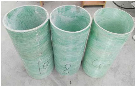
Three types of GFRP tubes with different diameter-thickness ratio
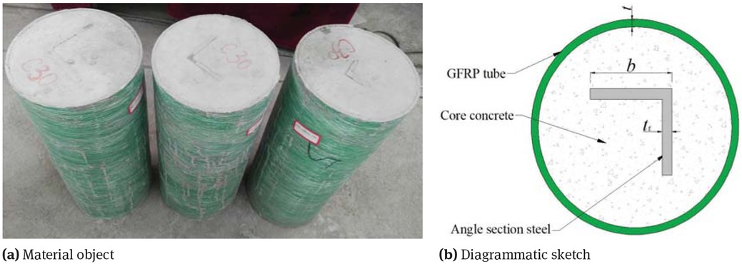
Sketch of cross section of nano-silica concrete-filled angle steel reinforced GFRP tubular column
Geometrical parameters for angle section steel
| Steel size | b (mm) | tf (mm) | As (mm2) |
|---|---|---|---|
| Small | 40 | 3.0 | 236 |
| Middle | 70 | 5.0 | 687 |
| Large | 90 | 6.0 | 1060 |
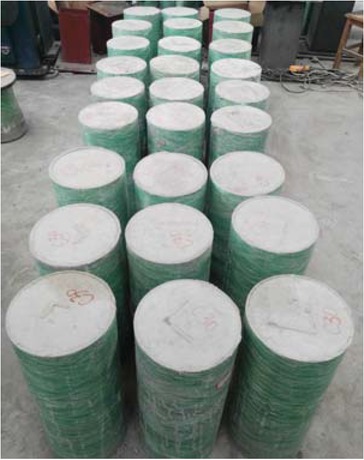
All composite columns before compression test
Test specimens were labeled according to the three parameters (GFRP tube’s diameter-to-thickness ratio, steel ratio and nano-silica concrete compressive strength). For example, the label ‘ζ 25-ψ0.034-C30’ is defined as the following specimen:
The first part ‘ζ 25’ denotes that the diameter-to-thickness ratio of GFRP tube is 25.
The second part of the label ‘ψ0.034’ denotes that steel ratio of the specimen is 0.034.
The last part of the label ‘C30’ indicates that the design nano-silica concrete compressive strength of specimens is 30MPa.
2.2 Material properties
The hot rolled Q235 angle section steel was used to make specimens. To obtain the properties of angle section steel, the study carried out three basic tensile coupon tests, and such tensile coupons were randomly cut from the steel plates. The tensile tests produced the following results: the average value of yield strength is 240.6MPa, the average value of ultimate tensile strength is 372.9MPa and the average value of elastic modulus for the angle section steel is 207.3GPa.
Hydrophilic-380 nano SiO2 were used to make the nano-silica concrete, the specific surface area of the nano SiO2 is 380 mm2/g and the particle size is 7-40nm. The crushed stone with the maximum size of 30mm and the natural medium sand were used as the coarse aggregate and the fine aggregate. The strength grade of the common Portland cement is 32.5 and the tap water is used for the nano-silica concrete. According to three types of conventional concrete in the design of concrete structures code, three kinds of modified nano-silica concrete with corresponding strength grade were prepared. Table 3 shows the mix proportion of nano-silica concrete. The measurement of the cubic compressive strength (fcu) is drawn from standard concrete cube tests (150mm×150×mm×150mm). The results of standard concrete cube tests are shown in Table 4, where fcu,m is average value of the standard cube compressive strength, fc,m is cylinder strength of concrete (fc,m = 0.8fcu,m). The Hydrophilic-380 nano SiO2 and the prepared nano-silica concrete are shown in Figure 4.
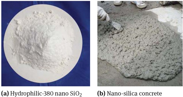
Nano-silica concrete preparation
Mix proportion of nano-silica concrete
| Concrete | Dosage of per cubic meter (kg) | |||
|---|---|---|---|---|
| strength (fc) | Nano SiO2 | Sand | Cement | Water |
| C20 | 13.5 | 690.0 | 350.0 | 185.0 |
| C30 | 13.5 | 600.0 | 450.0 | 183.0 |
| C40 | 13.5 | 525.0 | 520.0 | 178.0 |
Results of standard concrete cube tests
| Design strength | Standard cube compressive strength | Average value | Cylinder strength of concrete |
|---|---|---|---|
| (fc) | / MPa (fcu) | / MPa (fcu,m) | / MPa (fc,m) |
| 22.1 | |||
| C20 | 23.2 | 22.4 | 17.9 |
| 21.9 | |||
| 31.8 | |||
| C30 | 33.2 | 33.0 | 26.4 |
| 34.1 | |||
| 43.4 | |||
| C40 | 42.2 | 42.5 | 34.0 |
| 41.9 |
A two-axis filament winding machine was utilized in the manufacture of the GFRP tubes. The glass fiber’s angle is pegged at ±45◦, taking into account the hoop direction. The corresponding circumferential tensile strength of the GFRP is 430 MPa, and its Elastic module is 22 GPa.
2.3 Compressive tests on specimens
To have a better understanding and a comprehensive knowledge of the mechanical behaviors of the composite columns, strain gauges were used on four typical test specimens (specimen ζ 20-ψ0.034-C40, ζ40-ψ0.034-C40, ζ40-ψ0.034-C20 and ζ40-ψ0.008-C40) to obtain local strain distributions. The longitudinal and transverse strain gauges were positioned on two locations with an interval of 90◦ at the mid-height section of the GFRB tube. Overall, four strain gauges were utilized in every specimen. The arrangement of strain gauges is shown in Figure 5. ϵ1 and ϵ3 measure the longitudinal strain, ϵ2 and ϵ4 measure the transverse strain. Strain Measurement System DH3816 was used to get the strain of each gauge in the test.
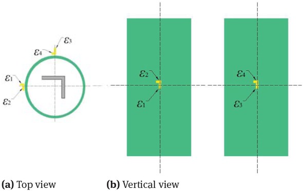
Arrangements of strain gauges
A universal testing machine with a capacity of 4500kN was used in the compression tests. To avoid the eccentric force, the top and bottom surfaces of specimens were polished off and parallel with the platform. The loading was controlled by force, and the loading rate was 2kN/s. The entire test system is shown in Figure 6.
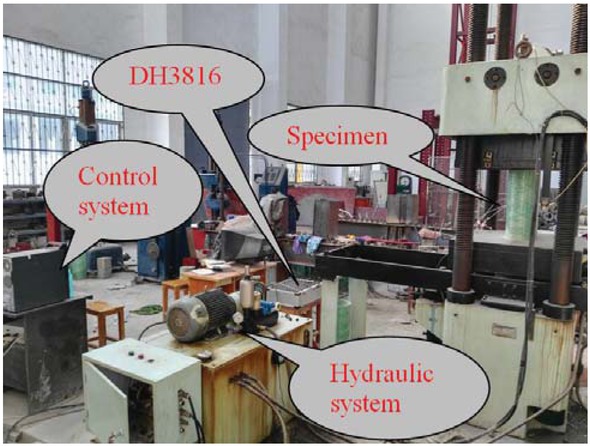
Loading system
3 Test results and discussion
3.1 Failure modes
The experimental phenomena of all test specimens were similar under axial load. In the earlier stage of loading, the fiber in the GFRP tube functioned gradually and made a slight sound. When the load achieved about sixty percent of the ultimate load, the surface of GFRP tube started to appear some striae albicantes. What’s more, the color of fibrous coat changed from ondine to uneven local white.
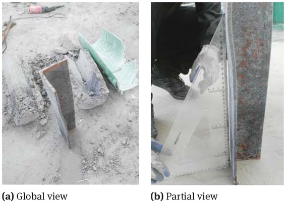
When the load achieved about ninety percent of the ultimate load, the sheared fiber bundles started to peel from fracture along the direction of fiber winding. When the load achieved the ultimate load, the GFRP tube cracked suddenly and the loud sound “peng” could be heard, thus making the test specimen destroyed. Several typical specimens after compression test were shown in Figure 7. After the compression test, the GFRP tube were cut open and removed, as shown in Figure 8. As reflected in Figure 8, crushed nano-silica concrete core could be observed at the place where the fiber bundle sheared. What’s more, there were many vertical cracks in the nano-silica concrete body. The core nano-silica concrete was also removed to observe the deformation of the angle steel after loading, as shown in Figure 9. Both overall buckling and local buckling could be observed.
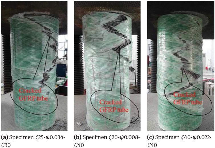
Failure mode of the columns
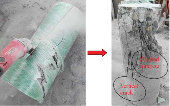
Core nano-silica concrete after the GFRP tube removed
Shape of angle section steel after the GFRP tube and nano-silica concrete removed
3.2 Load versus strain curves
Figure 10 shows a set of specimens’ typical load-strain curves. Strains of the four specimens under load are listed in Table 5. As shown in Table 5, ϵh is the average value of the two hoop strains of each specimen, given ϵh = (ϵ1 + ϵ3)/2. ϵa is the average value of the two axial strains of each specimen, given ϵa = (ϵ2 + ϵ4)/2. Based on the test data, the load-strain curves of the four specimens can be obtained, as shown in Figure 10. The maximum hoop strain in the linear stage is about 400×10−6~600×10−6, the maximum axial strain in the linear stage is about 1600×10−6~2400×10−6. It can be seen from Figure 10 that the slope of the P-ϵh curve is about four times as large as that of the corresponding P-ϵa curve (compare the P-ϵh curve and P-ϵa curve of the same specimen), indicate that the axial strain is about four times as large as that of the corresponding hoop strain under the same axial load in the first linear stage. The strain of specimen ζ 20-ψ0.034-C40 is larger than that of specimen ζ40-ψ0.034-C40 under the same load, infer that the strain of the specimen with smaller diameter-to-thickness ratio of GFRP tube develop slower with the increase of axial load. The slope of the load-strain curve of specimen ζ40-ψ0.034-C40 is larger than that of specimen ζ40-ψ0.034-C20 under the same load, indicate that the strain of the specimen with higher concrete compressive strength develop slower with the increase of axial load. Load-strain curve of specimen ζ40-ψ0.034-C40 and specimen ζ40-ψ0.008-C40 has no great difference, indicate that steel ratio has no great influence on the development of the strain with the increase of axial load.
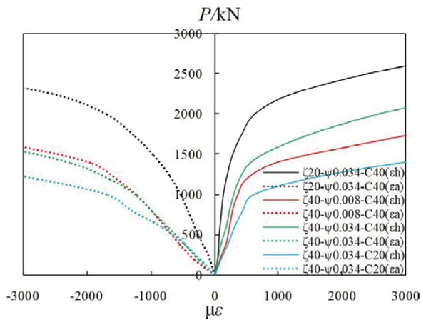
Load-strain curves of the specimens
Strains of the specimens
| Specimens | P (kN) | ϵ1 | ϵ2 | ϵ3 | ϵ4 | ϵh | ϵa |
|---|---|---|---|---|---|---|---|
| 0 | 2 | 0 | 1 | 0 | 2 | 0 | |
| 250 | 63 | −105 | 39 | −96 | 51 | −101 | |
| 500 | 77 | −273 | 69 | −242 | 73 | −258 | |
| 750 | 117 | −404 | 90 | −364 | 104 | −384 | |
| 1000 | 164 | −565 | 114 | −513 | 139 | −539 | |
| 1250 | 231 | −763 | 155 | −677 | 193 | −720 | |
| ζ 20-ψ0.034-C40 | 1500 | 358 | −1068 | 208 | −867 | 283 | −968 |
| 1750 | 580 | −1485 | 266 | −1059 | 423 | −1272 | |
| 2000 | 947 | −2111 | 314 | −1289 | 631 | −1700 | |
| 2250 | 1817 | −3377 | 586 | −1736 | 1202 | −2557 | |
| 2500 | 3548 | −6281 | 1276 | −2458 | 2412 | −4370 | |
| 2750 | 5625 | −9123 | 2321 | −3254 | 3973 | −6189 | |
| 3000 | 6350 | −10557 | 3896 | −5647 | 5123 | −8102 | |
| 0 | 8 | 1 | −2 | 0 | 3 | 1 | |
| 200 | 237 | −523 | −71 | −130 | 83 | −327 | |
| 400 | 327 | −896 | 27 | −250 | 177 | −573 | |
| 600 | 369 | −1159 | 90 | −402 | 230 | −781 | |
| 800 | 419 | −1336 | 147 | −654 | 283 | −995 | |
| ζ 40-ψ0.008-C40 | 1000 | 482 | −1553 | 229 | −895 | 356 | −1224 |
| 1200 | 573 | −1841 | 434 | −1230 | 504 | −1536 | |
| 1400 | 845 | −2433 | 1127 | −1485 | 986 | −1959 | |
| 1600 | 1381 | −3471 | 2810 | −2665 | 2096 | −3068 | |
| 1800 | 2036 | −4814 | 4828 | −4164 | 3432 | −4489 | |
| 0 | 0 | 0 | 0 | 0 | 0 | 0 | |
| 200 | 89 | −438 | 13 | −76 | 51 | −257 | |
| 400 | 159 | −784 | 32 | −191 | 96 | −488 | |
| 600 | 297 | −1183 | 58 | −296 | 178 | −740 | |
| 800 | 404 | −1516 | 73 | −446 | 239 | −981 | |
| 1000 | 493 | −1862 | 109 | −629 | 301 | −1246 | |
| ζ 40-ψ0.034-C40 | 1200 | 639 | −2419 | 155 | −880 | 397 | −1650 |
| 1400 | 907 | −3309 | 242 | −1255 | 575 | −2282 | |
| 1600 | 1451 | −4736 | 565 | −2155 | 1008 | −3446 | |
| 1800 | 2235 | −6552 | 1143 | −3674 | 1689 | −5113 | |
| 2000 | 3207 | −8655 | 1954 | −5638 | 2581 | −7147 | |
| 2200 | 4406 | −11414 | 2968 | −8254 | 3687 | −9834 | |
| 2400 | 5746 | −14635 | 4139 | −11243 | 4943 | −12939 | |
| 0 | 0 | 0 | 3 | 0 | 2 | 0 | |
| 200 | 102 | −231 | 112 | −251 | 107 | −173 | |
| 400 | 214 | −505 | 218 | −532 | 216 | −344 | |
| 600 | 305 | −845 | 316 | −913 | 311 | −582 | |
| 800 | 432 | −1299 | 445 | −1325 | 439 | −888 | |
| ζ 40-ψ0.034-C20 | 1000 | 589 | −1696 | 607 | −1736 | 598 | −1178 |
| 1200 | 1417 | −2783 | 1542 | −2817 | 1480 | −2080 | |
| 1400 | 2915 | −4376 | 3058 | −4423 | 2987 | −3646 | |
| 1600 | 4965 | −6650 | 5123 | −6698 | 5044 | −5948 | |
| 1800 | 6212 | −9214 | 7123 | −9314 | 6668 | −8613 | |
3.3 Axial load- displacement relationships
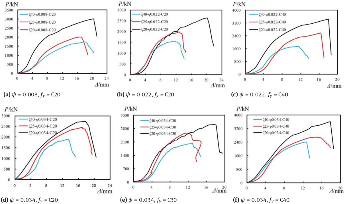
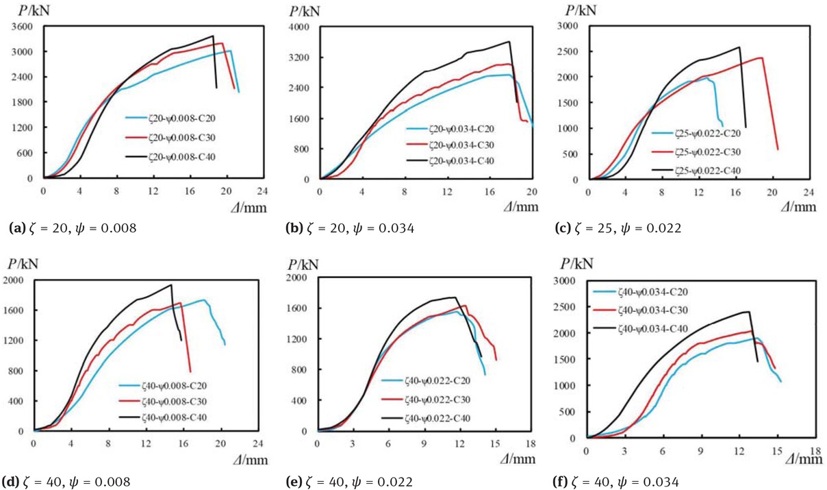
Figure 11, Figure 12 and Figure 13 show the axial load versus displacement curves for the typical specimens. The curves consist of the first initial stage, the second elastic stage, and the last elastic-plastic stage. The slope of the curves was very gentle during the initial stage. Since the core nano-silica concrete had not yet been pressed hard, the constraint effect of GFRP tube on the core nano-silica concrete had not yet fully developed. The curve entered the elastic stage as the constraint effect fully developed with the increase of load. In this stage, the axial displacement is almost proportional to the axial load and the stiffness of the stage is higher than the other two stages.
Typical load-displacement curves under different diameter-to-thickness ratio of GFRP tube
Typical load-displacement curves under different nano-silica concrete strength
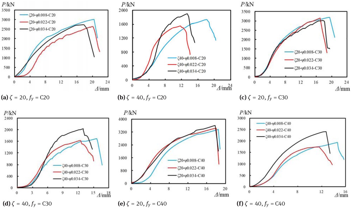
Typical load-displacement curves under different steel ratio
Compared with the elastic stage, the axial deformation of the specimen increased faster and the stiffness decreased in the elastic-plastic stage. The stiffness of the column declined with the increase of the load until the specimen was broken in this stage. Because the brittle failure of the GFRP tube when the load of the specimen achieves ultimate load, the curves bend suddenly downward.
As reflected in Figure 11, the specimen’s stiffness with different diameter-to-thickness ratio of GFRP tube has no great difference in the elastic stage. The stiffness of the specimens does not change with varieties of the diameter-to-thickness ratio of GFRP tube regularly. The ultimate load of the specimen increases with the decrease of diameter-to-thickness ratio of GFRP tube. Specimens with smaller diameter-to-thickness ratios of GFRP tube have a longer elastic-plastic stage. What’s more, the axial displacement corresponding to the ultimate load is also increase with the decrease of the diameter-to-thickness ratio of GFRP tube. Thicker GFRP tube supplies higher lateral confinement to core nano-silica concrete, so specimen with thicker GFRP tube has higher axial compression resistance. The effects of having a greater confining pressure across the crack face include delayed failure and higher shear capacity.
Figure 12 presents the effects of nano-silica concrete compressive strength on the specimens’ axial deformation behavior. From Figure 12, the ultimate load of the specimen increase with the increase of nano-silica concrete compressive strength. It can also be seen from Figure 12 that the displacement at the ultimate load of specimen with higher concrete compressive strength is smaller than that of those specimens with lower concrete compressive strength. This leads to the conclusion that increasing the nano-silica concrete compressive strength can increase the load bearing capacity of the composite column, but decrease the deformation capacity. Furthermore, the figure shows that in the elastic stage, curves of those specimens with higher nano-silica concrete compressive strength have a deeper slope, signifying a higher stiffness. What’s more, the stiffness of specimens with concrete strength C40 is larger than that of the specimens with concrete compressive strength C20 and C30 obviously in the elastic phase, but the stiffness of the specimens with concrete compressive strength C20 and C30 have no great difference.
Figure 13 presents how steel ratio affects the axial deformation behavior of the specimens. Based on the figure, the axial deformation behavior of the specimens does not change with varieties of the steel ratio regularly if the steel ratios range from 0.08 to 0.034.
3.4 Load bearing capacity
Within the period of loading process, the maximum load is defined as the ultimate load (Pu) of the specimens. The ultimate load of each specimen is listed in Table 6. What’s more, Figure 14 displays the ultimate load versus nano-silica concrete strength curves. It can be seen from Figure 14 that the ultimate load increases obviously with the increase of the nano-silica concrete compressive strength. In addition, it is found that the develop trend of these curves is the same. Generally, the ultimate load of the specimen increase linearly with the increase of nano-silica concrete compressive strength. The ultimate loads of the specimens with nano-silica concrete compressive strength of C30 increased 4.55% ~ 21.69% compared with that of the specimens with nano-silica concrete compressive strength of C20 (each of the two intercompared specimens are under the same diameter-to-thickness ratio of GFRP tube and steel ratio). The ultimate loads of the specimens with nano-silica concrete compressive strength of C40 increased 5.09% ~ 33.13% compared with that of the specimens with nano-silica concrete compressive strength of C30 (each of the two intercompared specimens are under the same diameter-to-thickness ratio of GFRP tube and steel ratio). The ultimate loads of the specimens with nano-silica concrete compressive strength of C40 increased 9.87% ~ 48.49% compared with that of the specimens with nano-silica concrete compressive strength of C20 (each of the two intercompared specimens are under the same diameter-to-thickness ratio of GFRP tube and steel ratio).
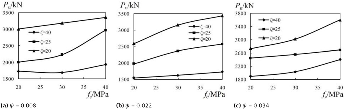
Ultimate load versus nano-silica concrete strength curves
Test results for all specimens
| Labels | Pu (kN) | Δ0.6 (mm) | Δu (mm) | DC | PuF (kN) | PuF/Pu |
|---|---|---|---|---|---|---|
| ζ 40-ψ0.008-C20 | 1728.4 | 8.3 | 18.1 | 2.2 | 1672.8 | 0.97 |
| ζ 40-ψ0.008-C30 | 1691.5 | 6.9 | 15.6 | 2.3 | 1929.5 | 1.14 |
| ζ 40-ψ0.008-C40 | 1931.2 | 6.4 | 14.7 | 2.3 | 2161.5 | 1.12 |
| ζ 40-ψ0.022-C20 | 1550.2 | 5.1 | 11.7 | 2.3 | 1747.0 | 1.13 |
| ζ 40-ψ0.022-C30 | 1627.8 | 5.5 | 12.4 | 2.3 | 1768.6 | 1.09 |
| ζ 40-ψ0.022-C40 | 1733.6 | 5.3 | 11.5 | 2.2 | 1863.8 | 1.08 |
| ζ 40-ψ0.034-C20 | 1896.8 | 6.5 | 13.4 | 2.1 | 1806.2 | 0.95 |
| ζ 40-ψ0.034-C30 | 2035.0 | 6.2 | 13.0 | 2.1 | 2049.5 | 1.01 |
| ζ 40-ψ0.034-C40 | 2404.2 | 5.5 | 12.7 | 2.3 | 2269.4 | 0.94 |
| ζ 25-ψ0.008-C20 | 1999.8 | 7.7 | 16.9 | 2.2 | 2179.6 | 1.09 |
| ζ 25-ψ0.008-C30 | 2230.6 | 5.1 | 10.9 | 2.1 | 2436.3 | 1.09 |
| ζ 25-ψ0.008-C40 | 2969.6 | 7.4 | 18.4 | 2.5 | 2668.3 | 0.90 |
| ζ 25-ψ0.022-C20 | 1979.0 | 5.9 | 12.8 | 2.2 | 2246.5 | 1.14 |
| ζ 25-ψ0.022-C30 | 2363.8 | 7.2 | 18.6 | 2.6 | 2495.8 | 1.06 |
| ζ 25-ψ0.022-C40 | 2575.0 | 7.4 | 16.3 | 2.2 | 2721.1 | 1.06 |
| ζ 25-ψ0.034-C20 | 2447.2 | 7.0 | 16.9 | 2.4 | 2299.6 | 0.94 |
| ζ 25-ψ0.034-C30 | 2558.6 | 5.9 | 11.6 | 2.0 | 2542.9 | 0.99 |
| ζ 25-ψ0.034-C40 | 2688.8 | 6.2 | 14.7 | 2.4 | 2762.8 | 1.03 |
| ζ 20-ψ0.008-C20 | 3008.2 | 6.7 | 20.4 | 3.0 | 2561.3 | 0.85 |
| ζ 20-ψ0.008-C30 | 3187.4 | 6.9 | 19.4 | 2.8 | 2754.3 | 0.86 |
| ζ 20-ψ0.008-C40 | 3364.0 | 7.7 | 18.5 | 2.4 | 2986.2 | 0.89 |
| ζ 20-ψ0.022-C20 | 2591.3 | 8.2 | 19.1 | 2.3 | 2559.8 | 0.99 |
| ζ 20-ψ0.022-C30 | 3153.4 | 7.4 | 17.0 | 2.3 | 2809.2 | 0.89 |
| ζ 20-ψ0.022-C40 | 3438.4 | 6.3 | 18.0 | 2.9 | 3034.5 | 0.88 |
| ζ 20-ψ0.034-C20 | 2730.0 | 7.2 | 17.7 | 2.5 | 2609.1 | 0.96 |
| ζ 20-ψ0.034-C30 | 3025.2 | 6.9 | 17.7 | 2.6 | 2852.5 | 0.94 |
| ζ 20-ψ0.034-C40 | 3598.6 | 7.1 | 17.8 | 2.5 | 3072.3 | 0.85 |
| Mean | 0.99 | |||||
| Max | 1.14 | |||||
| Min | 0.85 | |||||
| Standard deviation | 0.01 | |||||
Ultimate load versus diameter-to-thickness ratio of GFRP tube curves are shown in Figure 15. The diameter-thickness ratio of GFRP tube has a great influence on the ultimate load of the specimens. The ultimate load decreased obviously as the diameter-to-thickness ratio of GFRP tube increased. The slope of these curves decrease with the increase of the concrete compressive strength, infer that the decreasing rate of the ultimate load getting smaller with increase of the diameter-to-thickness ratio of GFRP tube. What’s more, the develop trend of these curves is generally the same, indicate that effect of the diameter-to-thickness ratio of GFRP tube on the ultimate load of the composite columns with different concrete compressive strength and steel ratio is similar. The ultimate loads of the specimens with diameter-to-thickness of GFRP tube of 25 decreased 10.36% ~ 33.52%compared with that of the specimens with diameter-to-thickness ratio of GFRP tube of 20 (each of the two intercompared specimens are under the same concrete compressive strength and steel ratio). The ultimate loads of the specimens with diameter-to-thickness ratio of GFRP
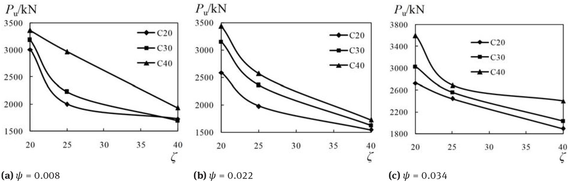
Ultimate load versus diameter-thickness ratio of GFRP tube curves
tube of 40 decreased 20.46% ~ 34.97%compared with that of the specimens with diameter-to-thickness ratio of GFRP tube of 25 (each of the two intercompared specimens are under the same concrete compressive strength and steel ratio). The ultimate loads of the specimens with diameter-thickness of GFRP tube of 40 decreased 30.52% ~ 49.58% compared with that of the specimens with diameter-to-thickness ratio of GFRP tube of 20 (each of the two inter-compared specimens are under the same concrete compressive strength and steel ratio). As shown in Figure 16, the ultimate loads of the specimens fluctuate with the steel ratios. So when the steel ratio of the specimens increase, the ultimate load of them may not increase as expected.
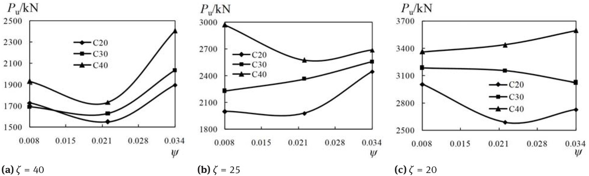
Ultimate load versus steel ratio curves
3.5 Confinement coefficient
The main function of GFRP tube is to provide confinement to the internal material. Thus, in order to assess the confinement effect of GFRP tube on angle section steel reinforced core nano-silica concrete, the confinement coefficient γ is defined as:
Where Pu represents the load-bearing capacity of the columns under axial load, As and Ac are the cross-sectional area of the angle section steel and the core nano-silica concrete, respectively. fy is the yield strength of the angle section steel, fc,m is the cylinder strength of nano-silica concrete, and fc,m = 0.8fcu,m. All the confinement coefficients of the specimens were list in Table 6, which span from 1.46 to 3.96.
Figure 17 shows the effect of diameter-to-thickness ratio of GFRP tube on the confinement coefficient. The develop trend of the γ-ζ curves are similar to the Pu-ζ curves. This infer that the effect of diameter-to-thickness ratio of GFRP tube on the confinement coefficient is similar to the effect of diameter-thickness ratio of GFRP tube on the ultimate load. The confinement coefficient decreases with the increase of diameter-to-thickness ratio of GFRP tube, and the larger the diameter-to-thickness ratio is, the slower the confinement coefficient declines. The thicker GFRP tube gives more confinement to core nano-silica concrete, thus making the load bearing capacity of the core nano-silica concrete under triaxial stress is several times more than that of the core nano-silica concrete under uniaxial stress.

Confinement coefficient versus diameter-thickness ratio of GFRP tube curves
As is shown in Figure 18, with the increase of nano-silica concrete strength grade, the confinement coefficient of the specimen decreased gradually. Although the load bearing capacity of the specimen with higher nano-silica concrete compressive strength is much larger than that of the specimen with lower nano-silica concrete compressive strength, the confinement effect of the GFRP tube on the core nano-silica concrete decreases as the nano-silica concrete compressive strength increased.
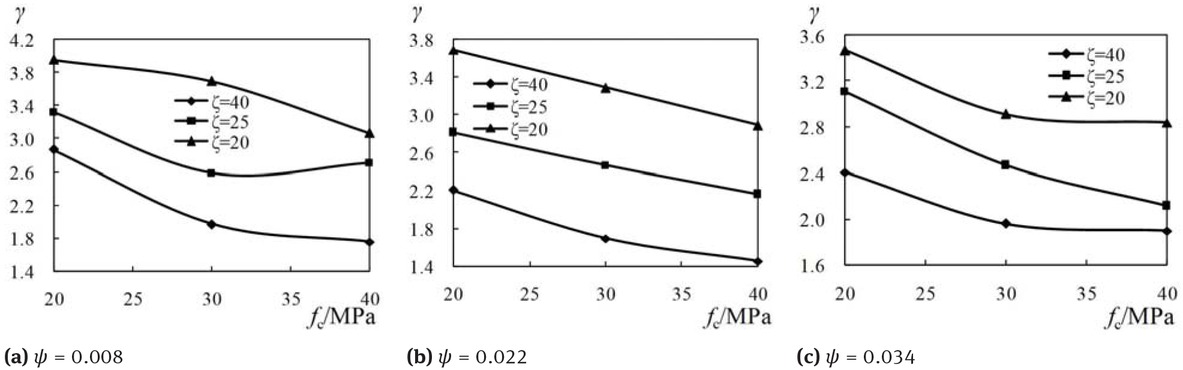
Confinement coefficient versus nano-silica concrete strength curves
Figure 19 shows the effect of steel ratio on the confinement coefficient. When ζ = 40 or ζ = 25, it can be seen from Figure 19(a, b) that the confinement coefficient decreased when the steel ratio changed from 0.008 to 0.022. Increasing the steel ratio from 0.022 to 0.034, the confinement coefficient does not change much. However, It can be seen from Figure 19(c), When ζ = 20, the confinement coefficient decreased with the increase of the steel ratio.
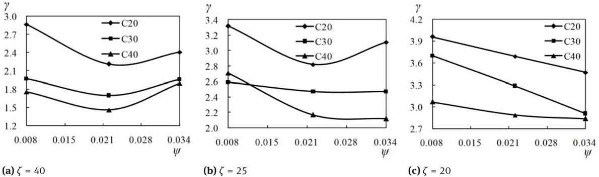
Confinement coefficient versus steel ratio curves
3.6 Ductility coefficient
The displacement at sixty percent of the ultimate load is defined as the yield displacement (Δ0.6). The displacement at the ultimate load is defined as the ultimate displacement (Δu). For the purpose of quantifying the ductility of the composite column, the present study made use of a ductility coefficient (DC), as following:
The results of calculated DC were shown in Table 6. These values ranged from 2.0 to 3.0, this indicates that, when the axial load reaches 0.6Pu, the displacement was less than half of the ultimate displacement. In this paper, 0.6Pu was proposed as the design load-bearing capacity of the column, and there were enough surpluses of the deformation and load bearing capacity of the column. The average value of ductility coefficient of the nine specimens with ζ = 40 is 2.2, the average value of ductility coefficient of the nine specimens with ζ = 25 is 2.3 and the average value of ductility coefficient of the nine specimens with ζ = 20 is 2.6. Infer that decrease the diameter-thickness ratio of GFRP tube can improve ductility of the composite column.
4 Design formulas for the load-bearing capacity
A corrected formula, according to the research of He et al. [35] on channel steel reinforced concrete-filled GFRP tubular short columns, has been proposed to calculate load-bearing capacity of nano-silica concrete-filled angle steel reinforced GFRP tubular columns under axial load based on the test results. The proposed formula can be expressed as follows.
Where Pu is the load-bearing capacity of nano-silica concrete-filled angle steel reinforced GFRP tubular columns under axial load, fcc is the conversion cross section strength of constrained steel reinforced nano-silica concrete in GFRP tube, and Ac is the cross-sectional area of nano-silica concrete. Using test results through regression analyses, the following corrected models of fcc are obtained:
Where f0 is the conversion strength of the unconstrained steel reinforced nano-silica concrete, described as:
σR is the ultimate confinement stress of GFRP tube to the steel reinforced core nano-silica concrete, given as:
Where fh is the ultimate hoop tensile strength of GFRP tube, t is thickness of GFRP tube, and D inner diameter of GFRP tube. The final formula can be expressed as:
To verify the accuracy of the proposed models, the calculated load-bearing capacity (PuF) were compared with the values obtained from test results (Pu). Table 6 shows the comparison. It can be observed from Table6 that the average ratio of PuF to Pu is 0.99, max value is 1.14, min value is 0.85, and standard deviation value is 0.01. The comparison results show a high accuracy of the proposed models in the load-bearing capacity prediction of the composite column.
5 Conclusions
This paper presents an experimental research on the nano-silica concrete-filled angle steel reinforced GFRP tubular columns. Based on the test results, the following major conclusions are concluded.
The failure mode of the composite column remains the same. All the test specimens failed due to the sudden rupture of the GFRP tube and the crushing of core nano-silica concrete.
Load bearing capacity of the composite column increases as the nano-silica concrete compressive strength increases. Higher concrete compressive strength can also lead to higher initial stiffness in the elastic stage. However, the composite column with higher concrete compressive strength shows lower deformation capacity. And the confinement effect of GFRP tube on lower strength concrete is better.
The initial stiffness of the composite column with different diameter-thickness ratio of GFRP tube has no great difference. As the diameter-thickness ratio of GFRP tube decreased, the confinement coefficient, load bearing capacity and deformation capacity of the composite column all increased.
Calculation formulas for the confinement coefficient and load-bearing capacity of the nano-silica concrete-filled angle steel reinforced GFRP tubular columns under axial load were recommended, and the predictions of the study coincided well with the experimental results.
Acknowledgement
This research work was supported by the National Natural Science Foundation of China (No. 51778066).
References
[1] Pawlowski R., Pawlowski B., Wita H., Silver nanoparticles in the thermal silver plating of aluminium busbar joints, Nanotechnol. Rev., 2018, 7(5), 365-372.10.1515/ntrev-2018-0032Search in Google Scholar
[2] Tseng K.H., Chou C.J., Liu T.C., Relationship between Ag nanoparticles and Ag ions prepared by arc discharge method, Nanotechnol. Rev., 2018, 7(1), 1-9.10.1515/ntrev-2017-0167Search in Google Scholar
[3] Karwowska E., Antibacterial potential of nanocomposite-based materials - a short review, Nanotechnol. Rev., 2017, 6(2), 243-254.10.1515/ntrev-2016-0046Search in Google Scholar
[4] Scott A., Vadalasetty K.P., Chwalibog A., Sawosz E., Copper nanoparticles as an alternative feed additive in poultry diet, a review, Nanotechnol. Rev., 2018, 7(1), 69-93.10.1515/ntrev-2017-0159Search in Google Scholar
[5] Shannahan J., The biocorona: a challenge for the biomedical application of nanoparticles, Nanotechnol. Rev., 2017, 6(4), 345-353.10.1515/ntrev-2016-0098Search in Google Scholar PubMed PubMed Central
[6] Zeidan M., Said A.M., Effect of colloidal nano-silica on alkalisilica mitigation, J. Sustainable Cem.-Based Mater., 2017, 6(2), 126-138.10.1080/21650373.2016.1191387Search in Google Scholar
[7] Kontoleontos F., Tsakiridis P.E., Marinos A., Kaloidas V., Katsioti M., Influence of colloidal nanosilica on ultrafine cement hydration: Physicochemical and microstructural characterization, Constr. Build. Mater., 2012, 35(35), 347-360.10.1016/j.conbuildmat.2012.04.022Search in Google Scholar
[8] Zhang M.H., Islam J., Peethamparan S., Use of nano-silica to increase early strength and reduce setting time of concretes with high volumes of slag, Cem. Concr. Compos., 2012, 34(5), 650-662.10.1016/j.cemconcomp.2012.02.005Search in Google Scholar
[9] Gupta M., Kumar M., Effect of nano silica and coir fiber on compressive strength and abrasion resistance of concrete, Constr. Build. Mater., 2019, 226, 44-50.10.1016/j.conbuildmat.2019.07.232Search in Google Scholar
[10] Lam L., Teng J.G., Stress–strain model for FRP-confined concrete under cyclic axial compression, Eng. Struct., 2009, 31, 308-321.10.1016/j.engstruct.2008.08.014Search in Google Scholar
[11] Teng J.G., Hu Y.M., Yu T., Stress–strain model for concrete in FRP-confined steel tubular columns, Eng. Struct., 2013, 49, 156-167.10.1016/j.engstruct.2012.11.001Search in Google Scholar
[12] Yu T., Hu Y.M., Teng J.G., FRP-confined circular concrete-filled steel tubular columns under cyclic axial compression, J. Constr. Steel Res., 2014, 94, 33-48.10.1016/j.jcsr.2013.11.003Search in Google Scholar
[13] Zhang D.J., Wang Y.F., Ma Y.S., Compressive behaviour of FRP-confined square concrete columns after creep, Eng. Struct., 2010, 32, 1957-1963.10.1016/j.engstruct.2010.02.023Search in Google Scholar
[14] Han L.H., Tao Z., Liao F.Y., Xu Y., Tests on cyclic performance of FRP–concrete–steel double-skin tubular columns, Thin-Walled Struct., 2010, 48, 430-439.10.1016/j.tws.2010.01.007Search in Google Scholar
[15] Hu B.,Wang J.G., Li G.Q., Numerical simulation and strength models of FRP-wrapped reinforced concrete columns under eccentric loading, Constr. Build. Mater., 2011, 25, 2751-2763.10.1016/j.conbuildmat.2010.12.036Search in Google Scholar
[16] Tidarut J., Zhang D.W., Tamon U., Prediction of the post-peak behavior of reinforced concrete columns with and without FRP-jacketing, Eng. Struct., 2013, 56, 1511-1526.10.1016/j.engstruct.2013.05.049Search in Google Scholar
[17] Feng P., Cheng S., Bai Y., Ye L.P., Mechanical behavior of concrete-filled square steel tube with FRP-confined concrete core subjected to axial compression, Compos. Struct., 2015, 123, 312-324.10.1016/j.compstruct.2014.12.053Search in Google Scholar
[18] Siddiqui N.A., Alsayed S.H., Al-Salloum Y.A., Iqbal R.A., Abbas H., Experimental investigation of slender circular RC columns strengthened with FRP composites, Constr. Build. Mater., 2014, 69, 323-334.10.1016/j.conbuildmat.2014.07.053Search in Google Scholar
[19] Tao Z., Teng J.G., Han L.H., Lam L., Experimental behaviour of FRP-confined slender RC columns under eccentric loading, Adv. Polym. Compos. Struct. Appl. Constr., Proc. Int. Conf., 2004, 203-212.10.1533/9781845690649.2.203Search in Google Scholar
[20] Pan J.L., Xu T., Hu Z.J., Experimental investigation of load carrying capacity of the slender reinforced concrete column wrapped with FRP, Constr. Build. Mater., 2007, 21, 1991-1996.10.1016/j.conbuildmat.2006.05.050Search in Google Scholar
[21] Tao Z., Han L.H., Behavior of fire-exposed concrete-filled steel tubular beam columns repaired with CFRP wraps, Thin-Walled Struct., 2007, 43, 445-452.10.1016/j.tws.2006.11.004Search in Google Scholar
[22] Teng J.G., Xiao Q.G., Yu T., Lam L., Three-dimensional finite element analysis of reinforced concrete columns with FRP and/or steel confinement, Eng. Struct., 2015, 97, 15-28.10.1016/j.engstruct.2015.03.030Search in Google Scholar
[23] Piscesa B., Attard M.M., Samani A.K., Three-dimensional finite element analysis of circular reinforced concrete column with FRP using plasticity model, Procedia Eng., 2017, 171, 847-856.10.1016/j.proeng.2017.01.377Search in Google Scholar
[24] Mazzucco G., Salomoni V.A., Majorana C.E., Pellegrino C., Ceccato C., Numerical investigation of concrete columns with external FRP jackets subjected to axial loads, Constr. Build. Mater., 2016, 111, 590-599.10.1016/j.conbuildmat.2016.02.050Search in Google Scholar
[25] Wang J., Feng P., Hao T.Y., Yue Q.R., Axial compressive behavior of seawater coral aggregate concrete-filled FRP tubes, Constr. Build. Mater., 2017, 147, 272-285.10.1016/j.conbuildmat.2017.04.169Search in Google Scholar
[26] Li Y.L., Zhao X.L., Singh R.K.R., Al-Saadi S., Experimental study on seawater and sea sand concrete filled GFRP and stainless steel tubular stub columns, Thin-Walled Struct., 2016, 106, 390-406.10.1016/j.tws.2016.05.014Search in Google Scholar
[27] Wu Y.F., Jiang C., Effect of load eccentricity on the stress–strain relationship of FRP-confined concrete columns, Compos. Struct., 2013, 98, 228-241.10.1016/j.compstruct.2012.11.023Search in Google Scholar
[28] Hadi M.N.S., Comparative study of eccentrically loaded FRP wrapped columns, Compos. Struct., 2006, 74, 127-135.10.1016/j.compstruct.2005.03.013Search in Google Scholar
[29] Csuka B., Kollár L.P., Analysis of FRP confined columns under eccentric loading, Compos. Struct., 2012, 94, 1106-1116.10.1016/j.compstruct.2011.10.012Search in Google Scholar
[30] Hassan W.M., Hodhod O.A., Hilal M.S., Bahnasaway H.H., Behavior of eccentrically loaded high strength concrete columns jacketed with FRP laminates, Constr. Build. Mater., 2017, 138, 508-527.10.1016/j.conbuildmat.2017.02.016Search in Google Scholar
[31] Huang L., Yin P., Yan L.b., Kasal B., Behavior of hybrid GFRP– perforated-steel tube-encased concrete column under uniaxial compression, Compos. Struct., 2016, 142, 313-324.10.1016/j.compstruct.2016.02.016Search in Google Scholar
[32] Wang L., Liu W.Q., Hui D., Compression strength of hollow sandwich columns with GFRP skins and a paulownia wood core, Composites, Part B, 2014, 60, 495-506.10.1016/j.compositesb.2014.01.013Search in Google Scholar
[33] Zhu C.Y., Zhao Y.H., Gao S., Li X.F., Mechanical behavior of concrete filled glass fiber reinforced polymer-steel tube under cyclic loading, J. Zhejiang Univ-Sc. A, 2013, 14, 778-788.10.1631/jzus.A1300206Search in Google Scholar
[34] Wang L.G., Han H.F., Liu H.P., Behavior of reinforced concrete-filled GFRP tubes under eccentric compression loading, Mater. Struct., 2016, 49, 2819-2827.10.1617/s11527-015-0688-1Search in Google Scholar
[35] He K., Chen Y., Experimental evaluation of built-in channel steel concrete-filled GFRP tubular stub columns under axial compression, Compos. Struct., 2019, 219, 51-68.10.1016/j.compstruct.2019.03.057Search in Google Scholar
© 2019 K. He et al., published by De Gruyter
This work is licensed under the Creative Commons Attribution 4.0 Public License.
Articles in the same Issue
- Research Articles
- Investigation of rare earth upconversion fluorescent nanoparticles in biomedical field
- Carbon Nanotubes Coated Paper as Current Collectors for Secondary Li-ion Batteries
- Insight into the working wavelength of hotspot effects generated by popular nanostructures
- Novel Lead-free biocompatible piezoelectric Hydroxyapatite (HA) – BCZT (Ba0.85Ca0.15Zr0.1Ti0.9O3) nanocrystal composites for bone regeneration
- Effect of defects on the motion of carbon nanotube thermal actuator
- Dynamic mechanical behavior of nano-ZnO reinforced dental composite
- Fabrication of Ag Np-coated wetlace nonwoven fabric based on amino-terminated hyperbranched polymer
- Fractal analysis of pore structures in graphene oxide-carbon nanotube based cementitious pastes under different ultrasonication
- Effect of PVA fiber on durability of cementitious composite containing nano-SiO2
- Cr effects on the electrical contact properties of the Al2O3-Cu/15W composites
- Experimental evaluation of self-expandable metallic tracheobronchial stents
- Experimental study on the existence of nano-scale pores and the evolution of organic matter in organic-rich shale
- Mechanical characterizations of braided composite stents made of helical polyethylene terephthalate strips and NiTi wires
- Mechanical properties of boron nitride sheet with randomly distributed vacancy defects
- Fabrication, mechanical properties and failure mechanism of random and aligned nanofiber membrane with different parameters
- Micro- structure and rheological properties of graphene oxide rubber asphalt
- First-principles calculations of mechanical and thermodynamic properties of tungsten-based alloy
- Adsorption performance of hydrophobic/hydrophilic silica aerogel for low concentration organic pollutant in aqueous solution
- Preparation of spherical aminopropyl-functionalized MCM-41 and its application in removal of Pb(II) ion from aqueous solution
- Electrical conductivity anisotropy of copper matrix composites reinforced with SiC whiskers
- Miniature on-fiber extrinsic Fabry-Perot interferometric vibration sensors based on micro-cantilever beam
- Electric-field assisted growth and mechanical bactericidal performance of ZnO nanoarrays with gradient morphologies
- Flexural behavior and mechanical model of aluminum alloy mortise-and-tenon T-joints for electric vehicle
- Synthesis of nano zirconium oxide and its application in dentistry
- Surface modification of nano-sized carbon black for reinforcement of rubber
- Temperature-dependent negative Poisson’s ratio of monolayer graphene: Prediction from molecular dynamics simulations
- Finite element nonlinear transient modelling of carbon nanotubes reinforced fiber/polymer composite spherical shells with a cutout
- Preparation of low-permittivity K2O–B2O3–SiO2–Al2O3 composites without the addition of glass
- Large amplitude vibration of doubly curved FG-GRC laminated panels in thermal environments
- Enhanced flexural properties of aramid fiber/epoxy composites by graphene oxide
- Correlation between electrochemical performance degradation and catalyst structural parameters on polymer electrolyte membrane fuel cell
- Materials characterization of advanced fillers for composites engineering applications
- Humic acid assisted stabilization of dispersed single-walled carbon nanotubes in cementitious composites
- Test on axial compression performance of nano-silica concrete-filled angle steel reinforced GFRP tubular column
- Multi-scale modeling of the lamellar unit of arterial media
- The multiscale enhancement of mechanical properties of 3D MWK composites via poly(oxypropylene) diamines and GO nanoparticles
- Mechanical properties of circular nano-silica concrete filled stainless steel tube stub columns after being exposed to freezing and thawing
- Arc erosion behavior of TiB2/Cu composites with single-scale and dual-scale TiB2 particles
- Yb3+-containing chitosan hydrogels induce B-16 melanoma cell anoikis via a Fak-dependent pathway
- Template-free synthesis of Se-nanorods-rGO nanocomposite for application in supercapacitors
- Effect of graphene oxide on chloride penetration resistance of recycled concrete
- Bending resistance of PVA fiber reinforced cementitious composites containing nano-SiO2
- Review Articles
- Recent development of Supercapacitor Electrode Based on Carbon Materials
- Mechanical contribution of vascular smooth muscle cells in the tunica media of artery
- Applications of polymer-based nanoparticles in vaccine field
- Toxicity of metallic nanoparticles in the central nervous system
- Parameter control and concentration analysis of graphene colloids prepared by electric spark discharge method
- A critique on multi-jet electrospinning: State of the art and future outlook
- Electrospun cellulose acetate nanofibers and Au@AgNPs for antimicrobial activity - A mini review
- Recent progress in supercapacitors based on the advanced carbon electrodes
- Recent progress in shape memory polymer composites: methods, properties, applications and prospects
- In situ capabilities of Small Angle X-ray Scattering
- Review of nano-phase effects in high strength and conductivity copper alloys
- Progress and challenges in p-type oxide-based thin film transistors
- Advanced materials for flexible solar cell applications
- Phenylboronic acid-decorated polymeric nanomaterials for advanced bio-application
- The effect of nano-SiO2 on concrete properties: a review
- A brief review for fluorinated carbon: synthesis, properties and applications
- A review on the mechanical properties for thin film and block structure characterised by using nanoscratch test
- Cotton fibres functionalized with plasmonic nanoparticles to promote the destruction of harmful molecules: an overview