Miniature on-fiber extrinsic Fabry-Perot interferometric vibration sensors based on micro-cantilever beam
-
 ,
,

Abstract
An on-fiber extrinsic Fabry–Perot interferometric (EFPI) vibration sensor based on micro-cantilever beam is proposed and experimentally demonstrated. The micro-cantilever beam, with a cantilever length of 80μm and a cantilever thickness of 5μm, is created perpendicular to the fiber axis by using the femtosecond laser micro-machining technique. The on-fiber vibration sensor has same diameter with that of the single mode fiber. An acceleration sensitivity of 11.1 mV/g@300 Hz in the range of 0.5-5g is demonstrated experimentally. This on-fiber and micro-cantilever beam design allows for the sensor to be smaller size and higher temperature resistance.
1 Introduction
Vibration sensors have found wide applications in many areas such as in structural health monitoring [1], inertial navigation [2], earthquake monitoring [3] and even biomedicine [4]. Some of these applications, like endoscopic photoacoustic imaging [5] and turbine engines [6], require vibration sensors with small size, high sensitivity, biocompatible structure and high temperature resistance. However, most of commercially available vibration sensors (capacitive [7] or piezoelectric [8] based vibration transducers) suffer from oversize, electromagnetic interference and high temperature softening, which make them difficult for vibration measurements in such a harsh environment. In this case, optical fiber vibration sensors offer a potential solution as they possess many advantages over the conventional electrical vibration sensors such as being passive, small size, immunity to electromagnetic interference and amiability to high temperature conditions [9, 10].
Various types of optical fiber vibration sensors have been demonstrated. Early intensity-based optical fiber vibration sensors employ low cost and not very sophisticated instrumentation [11]. The main disadvantages of these vibration sensors are their low precision and stability. Fiber Bragg grating (FBG)-based vibration sensors are considered to have good sensitivity and unique multiplexing capability [10, 12, 13]. However, their sensor dimensions and the instability under high temperature have limited their applications. Fabry–Pérot interferometer (FPI)-based vibration sensors have played a dominant role due to their capacity for miniature size and high stability [14, 15, 16, 17, 18, 19]. These vibration sensors typically utilize a sensor head that carries an extrinsic Fabry–Pérot interferometric (EFPI) structure and a cantilever beam or support beam. In most cases, the dimension of the sensor head is larger than the optical fiber diameter and the applications of bonding materials (polymeric adhesives) may yield low tensile-strength structures. Consequently, the vibration range and long-term stability of these sensors are limited. By using the all-fiber sensor design, it is possible to reduce the vibration sensor diameter down to the Ø 125μm range [16, 17, 19]. Moreover, sensors with all-fiber structure proved to be robust and temperature and otherwise environmentally stable. The main obstacle is to operate on the fiber to fabricate a desired sensing structure. Chemical etching method has simple manufacturing steps and low costs [16]. However, due to the limited precision of the etching process, the sensor dimension is typically a few hundred micrometers. Two strategies have been followed to overcome the problem. The first is to employ focused ion beam (FIB) processing technique. With the combination of FIB technology and hydrofluoric acid etching, the cantilever structure has achieved a dozen micrometers diameter and high sensitivity to applied vibrations [17]. Two associated drawbacks of the FIB processing technique however are the costly equipment and the time it takes to machine the cantilever structure. The second and more appropriate approach towards an all-fiber solution is to use a femtosecond laser (FSL). While the FSL micromachining technique is not as accurate as the FIB processing technique, it shows higher efficiency and lower costs [19].
In this paper, we present an on-fiber EFPI vibration sensor with a micro-cantilever beam fabricated by a femtosecond laser. The micro-cantilever beam is created perpendicular to the fiber axis, which makes the cantilever length less than the diameter of single mode fiber. All the processing steps are straightforward and easy to operate.
2 Sensor design and fabrication
2.1 Design of the sensor structure
The designed vibration sensor consists of a standard lead-in single mode fiber (SMF), a hollow core fiber (HCF) and a micro-machined silica coreless fiber (CF), as shown in Figure 1. The end face of the SMF and the back surface of the CF form a Fabry–Perot (FP) cavity. The CF is processed into a micro-cantilever beam integrating with an inertial mass for vibration detecting. Under applied vibration acting on the sensor, the micro-cantilever beam deflects due to inertia and the inertial mass from the beam oscillates along the axial direction, resulting in a change in the cavity length correspondingly. Thus, the vibration can be detected by using the quadrature operating-point demodulation.

Schematic of the proposed on-fiber EFPI vibration sensor
2.2 Fabrication procedure of the sensor
Sensor fabrication consists of a sequence of steps which are shown in Figure 2. After a SMF (SMF-28e, Corning) and a HCF were cleaned and polished, the first splice between the SMF and the HCF was achieved by use of a commercial fiber splicer. The inner and outer diameter of the HCF is 93μm and 130μm respectively [Figure 2(a)]. Then the HCF was cleaved to a specified length (∼ 150μm) using a fiber cleaver under the assistance of an optical microscope [Figure 2(b)]. Next, the second splice was performed by splicing this sample to a coreless silica fiber (CF)
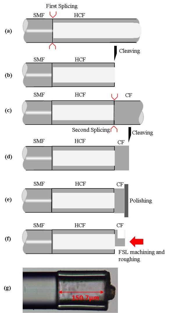
Fabrication procedure for the vibration sensor (a)–(f) and an optical microscope picture of a fabricated sensor (g)
[Figure 2(c)]. This was followed by cutting the CF ~50μm away from the spliced location [Figure 2(d)]. Afterwards, the CF was further polished to the needed length (30μm) to form a thin diaphragm [Figure 2(e)]. Finally, the SMF-HCF-CF sandwich structure was fixed on a hexapod six-axis stage and machined into a desired micro-cantilever beam structure by using the FSL [Figure 2(f)]. Figure 2(g) is an optical microscope picture of the side view of a typical vibration sensor fabricated by this method.
The micromachining procedures of the micro-cantilever beam structure was schematically described in Figure 3. The FSL (5 W, Spectra-Physics) with a central wavelength of 800 nm, a repetition rate of 1 kHz, a pulse width of 35 fs, and a pulse energy of 40 μJ was focused onto the outside surface of the CF (i.e., the diaphragm) by employing an objective lens (MPlan FL N, Olympus). Then a part of the CF was ablated to form a preliminary cantilever structure [Figure 3(a) - Figure 3(c)]. This structure had a length of about 80μm and a width of 45μm. Since the whole ablation region of the CF had to be cleaved until the hole of the HCF exposed, the preliminary thickness of the cantilever was equal to the thickness of diaphragm(30μm). Next, the preliminary cantilever was further trimmed in order to obtain a vibration -sensitive micro-cantilever beam structure. This was performed by thinning the upper part of the cantilever to an optimal dimension [Figure 3(d)], which determined the vibration sensitivity of the sensor. While the selection of a thinner cantilever would be feasible, the thinner cantilever might be frail and easy to crack. In this paper, the thickness of the cantilever was determined to be 5μm. After the updated micro-cantilever was machined, the undressed section can serve as the inertial mass. In Figure 3(e), the inertial mass was roughened to suppress unwanted back-reflections from its outer surface. Figure 3(f) shows the cross section of the machined micro-cantilever beam used in the experiment.

Micromachining procedures for micro-cantilever beam structure (a)–(e) and an optical microscope picture of the end face of a fabricated sensor (f)
During CF polishing [Figure 2(e)], the precise control over the CF thickness is achieved by connecting the sample to a homemade white-light interferometric (WLI) interrogator system (0.2 nm resolution and 1 Hz measurement frequency). The white-light interference spectrum was continuously obtained by the interrogator and the thickness of the CF can be calculated in real time. Figure 4 shows the interference spectrum of the representative sample whose CF thickness has been polished down to 30μm. The black line, which was obtained before the FSL micromachining, was the contribution of three reflectors, one from the end face of the SMF and the other two from both inner and outer surface of the CF. The three-beam interference is viewed as the superposition of two-beam interferences which can be interrogated (calculating the CF thickness) by using the FFT-based WLI and peak to peak method, as described in detail in our previous publication [20, 21, 22]. The red dashed curve was obtained after the inertial mass roughening [Figure 3(e)]. Note that the reflection from the outer surface of inertial mass has been suppressed and the two-beam interference with a fringe contrast of 5dB is formed.
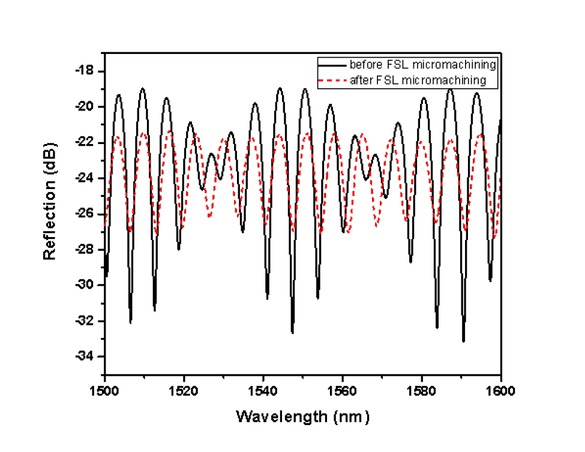
Interference spectrums before and after the FSL micromachining
3 Experiments and evaluations
3.1 Experimental setup
To obtain the vibration signal of the sensor, the quadrature operating-point demodulation technique is adopted by detecting the variation of operating point wavelength. When the incident light from the SMF is reflected at two fiber/air interfaces, a sinusoidal interference signal from the EFPI is formed. Typically, the operating point is chosen in the linear region of the sinusoidal interference signal to achieve a linear response with high sensitivity. In case of applied vibration, the variation in the operating point wavelength due to a change of the air cavity length provides the desired intensity variation of output voltages. This intensity variation is proportional to the applied vibration and can be used for vibration or acceleration detecting. The variation in the operating point wavelength can be described as: Δλl = λl · ΔL/L, where λl is the operating point wavelength, ΔL is the change of the air cavity length and L is the air cavity length [23].
The experimental setup for vibration tests is schematically shown in Figure 5. A distributed feedback (DFB) laser was used as the light source,whose center wavelength was 1550.02 nm. Light from the laser was launched into the vibration sensor through a coupler and the reflected light was detected by a photodetector (PD), followed by an amplifier circuit (Amp.). A data acquisition card (DAC) with a sampling frequency of 15 kHz was employed to sample the signal. The vibration sensor was fixed on a shaker (JSK-5T, Jiangsu Lianneng, China) where the cantilever beam was perpendicular to the vibration direction. A function generator and a power amplifier were connected to the shaker for signal generating and driving. When the shaker was excited and oscillated along the fiber axial direction, the applied vibration signal was sampled and processed. During oscillating, a piezoelectric vibration sensor (YD84T, Amphenol)was placed where the fiber sensor was to be tested for calibration purpose facilitated by a vibration meter (VT-63, Shanghai Wujiu, China).
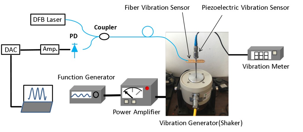
Experimental setup for vibration sensor evaluation
3.2 Time response and frequency response of the sensor
Figure 6 demonstrates the time response and related frequency response of the vibration sensor when an external oscillation with a frequency of 300 Hz and an acceleration of 2.5 g is applied to the shaker. The frequency spectrum of the sensor [Figure 6(b)] is given by the fast Fourier transform (FFT). It is seen that the FFT spectra has a signal-to-noise ratio (SNR) of 33 dB and the measured frequency is in agreement with the applied frequency. This coincidence can also be demonstrated from the vibrational spectrum of sensor [Figure 6(a)]whose amplitude would be used for acceleration measurements.

The demodulated vibration signals (a) and its FFT spectra (b) under the applied vibration frequency of 300 Hz and the acceleration of 2.5 g.
3.3 Acceleration response of the vibration sensor
Figure 7 shows the acceleration response of the vibration sensor versus the external oscillation. The frequency was adjusted to 300 Hz and the applied acceleration was determined by the vibration meter. Since the tip displacement of a cantilever-mass architecture is proportional to the acceleration, the amplitude of the vibrational spectrum can be considered as the result of the acceleration response. The applied acceleration began at 0.5g (almost 9.8 m/s2) and increased incrementally to 5 g in steps of 0.5 g. Each measurement was repeated five times and the mean value was recorded. As expected, the response amplitude shows good linearity with the applied acceleration, with a correlation coefficient (R) of 0.99078. The response sensitivity of sensor is estimated to be 11.1mV/g by calculating the slope of the linear fitting curve.
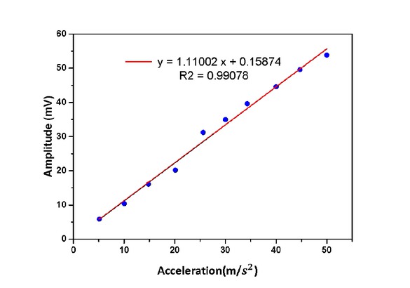
The acceleration response of the vibration sensor.
The temperature dependence of the vibration sensor was further investigated. The homemade WLI interrogator system was used to obtain the cavity length of the EFPI in different temperatures. The temperature dependence, which is attributed to the thermal expansion effect of the HCF, can be expressed as ΔL = L0 · α · ΔT, where αis the coefficient of thermal expansion of silica (0.55 × 10⁻⁶/∘C), L0 is the initial cavity length (150μm), ΔL and ΔT are the change of the EFPI cavity length and applied temperature respectively. Thus, the predicted temperature sensitivity of the sensor is calculated to be ΔL/ΔT = 0.083nm/∘C. Figure 8 shows experimental results of the cavity length as a function of applied temperature. Note that the measured EFPI cavity length has a good linear correlation to the applied temperature and the temperature sensitivity is obtained to be 0.0848 nm/∘C, which is in reasonable agreement with the predicted value of 0.083nm/∘C. In addition, the obtained temperature sensitivity indicate that fluctuations of ∼ 800∘C (the temperature measurement range) would induce a cavity length error of ΔL ≈ 67.84nm, resulting in a variation in the operating point wavelength of Δλl ≈ 0.7nm (λl ≈ 1550nm). Such a shift is very low compared to the FSR of the interference spectrum in Figure 4 and the temperature compensation would not be necessary.

The relationship between the cavity length and the applied temperature.
4 Conclusion
In conclusion, an on-fiber vibration sensor with a dimension as small as the standard fiber diameter (125μm) has been proposed and experimentally demonstrated. The vibration sensor is composed of a standard lead-in SMF, a HCF and a micro-machined CF, which has a micro-cantilever beam structure. The micro-cantilever beam is created perpendicular to the fiber axis, which makes the cantilever length (80μm) less than the standard fiber diameter. The end face of the SMF and the back surface of the micro-cantilever beam form an EFPI cavity. A representative sensor with an acceleration sensitivity of 11.1mV/gwas fabricated and tested. This on-fiber and cross-axial micro-cantilever beam designs render the sensor smaller size and higher temperature resistance.
Acknowledgement
This work was supported in part by the National Key R&D Program of China under Grant 2018YFB1107200, the National Natural Science Foundation of China (NSFC) under Grants 61775020 and 61575021.
Conflict of Interest
Conflict of Interests: The authors declare no competing financial interests regarding the publication of this paper.
References
[1] Strasberg M., Feit D., Vibration damping of large structures induced by attached small resonant structures, J. Acoust. Soc. Amer., 1996, 99, 335-344.10.1121/1.414545Suche in Google Scholar
[2] Tan C.W., Park S., Design of accelerometer-based inertial navigation systems, Ieee T. Instrum. Meas., 2005, 54, 2520-2530.10.1109/TIM.2005.858129Suche in Google Scholar
[3] Bertolini A., DeSalvo R., Fidecaro F., Francesconi M., Marka S., Sannibale V., Simonetti D., Takamori A., Tariq H., Mechanical design of a single-axis monolithic accelerometer for advanced seismic attenuation systems, Nucl. Instrum. Meth. A., 2006, 556, 616-623.10.1016/j.nima.2005.10.117Suche in Google Scholar
[4] Ashkenazi S., Hou Y., Buma T., O’Donnell M., Optoacoustic imaging using thin polymer etalon, Appl. Phys. Lett., 2005, 86.10.1063/1.1896085Suche in Google Scholar
[5] Zhang E.Z., Beard P.C., A miniature all-optical photoacoustic imaging probe, Photons Plus Ultrasound: Imaging And Sensing, 2011, 2011, 7899.10.1117/12.874883Suche in Google Scholar
[6] Maynard K., Trethewey M., Gill R., Resor B., Gas turbine blade and disk crack detection using torsional vibration monitoring: A feasibility study, Cond. Monitor. Diagn. Eng. Manag., 2001, 985-992.10.1016/B978-008044036-1/50116-5Suche in Google Scholar
[7] Kulah H., Chae J., Naiari K., Noise analysis and characterization of a sigma-delta capacitive silicon microaccelerometer, Boston Transducers’03: Digest of Technical Papers, 2003, 1,2, 95-98.10.1109/SENSOR.2003.1215261Suche in Google Scholar
[8] Tadigadapa S., Mateti K., Piezoelectric MEMS sensors: state-of-the-art and perspectives, Meas. Sci. Technol., 2009, 20(9), 092001.10.1088/0957-0233/20/9/092001Suche in Google Scholar
[9] Lee B., Review of the present status of optical fiber sensors, Opt. Fiber Technol., 2003, 9, 57-79.10.1016/S1068-5200(02)00527-8Suche in Google Scholar
[10] Tsuda H., Fiber Bragg grating vibration-sensing system, insensitive to Bragg wavelength and employing fiber ring laser, Opt. Lett., 2010, 35, 2349-2351.10.1364/OL.35.002349Suche in Google Scholar PubMed
[11] Kalenik J., Pajak, A cantilever optical-fiber accelerometer, Sensor Actuat. a-Phys., 1998, 68, 350-355.10.1016/S0924-4247(98)00066-1Suche in Google Scholar
[12] Basumallick N., Chatterjee I., Biswas P., Dasgupta K., Bandy-opadhyay S., Fiber Bragg grating accelerometer with enhanced sensitivity, Sensor Actuat. a-Phys., 2012, 173, 108-115.10.1016/j.sna.2011.10.026Suche in Google Scholar
[13] Guo T., Ivanov A., Chen C.K., Albert J., Temperature-independent tilted fiber grating vibration sensor based on cladding-core re-coupling, Opt. Lett., 2008, 33, 1004-1006.10.1364/OL.33.001004Suche in Google Scholar
[14] Ke T., Zhu T., Rao Y.J., Deng M., Accelerometer Based on All-Fiber Fabry-Perot Interferometer Formed by Hollow-Core Photonic Crystal Fiber, Microw. Opt. Techn. Let., 2010, 52, 2531-2535.10.1002/mop.25529Suche in Google Scholar
[15] Jia P.G., Wang D.H., Yuan G., Jiang X.Y., An Active Temperature Compensated Fiber-Optic Fabry-Perot Accelerometer System for Simultaneous Measurement of Vibration and Temperature, IEEE Sens. J., 2013, 13, 2334-2340.10.1109/JSEN.2013.2251879Suche in Google Scholar
[16] Zhang Q., Zhu T., Hou Y.S., Chiang K.S., All-fiber vibration sensor based on a Fabry-Perot interferometer and a microstructure beam, J. Opt. Soc. Am. B., 2013, 30, 1211-1215.10.1364/JOSAB.30.001211Suche in Google Scholar
[17] Andre R.M., Pevec S., Becker M., Dellith J., Rothhardt M., Marques M.B., Donlagic D., Bartelt H., Frazao O., Focused ion beam post-processing of optical fiber Fabry-Perot cavities for sensing applications, Opt. Express, 2014, 22, 13102-13108 .10.1364/OE.22.013102Suche in Google Scholar PubMed
[18] Li J., Wang G.Y., Sun J.N., Maier R.R.J., Macpherson W.N., Hand D.P., Dong F.Z., Micro-Machined Optical Fiber Side-Cantilevers for Acceleration Measurement, Ieee Photonic Tech. L., 2017, 29, 1836-1839.10.1109/LPT.2017.2753279Suche in Google Scholar
[19] Zhang L.C., Jiang Y., Jia J.S., Wang P., Wang S.M., Jiang L., Fiber-optic micro vibration sensors fabricated by a femtosecond laser, Opt. Laser Eng., 2018, 110, 207-210.10.1016/j.optlaseng.2018.06.003Suche in Google Scholar
[20] Jiang Y., Fourier transform white-light interferometry for the measurement of fiber-optic extrinsic Fabry-Perot interferometric sensors, IEEE Photonic Tech. L., 2008, 20, 75-77.10.1109/LPT.2007.912567Suche in Google Scholar
[21] Jiang Y., High-resolution interrogation technique for fiber optic extrinsic Fabry-Perot interferometric sensors by the peak-to-peak method, Appl. Optics, 2008, 47, 925-932 .10.1364/AO.47.000925Suche in Google Scholar
[22] Gao H.C., Jiang Y., Cui Y., Zhang L. C., Jia J.S., Hu J., Dual-Cavity Fabry-Perot Interferometric Sensors for the Simultaneous Measurement of High Temperature and High Pressure, IEEE Sens. J., 2018, 18, 10028-10033.10.1109/JSEN.2018.2875435Suche in Google Scholar
[23] Bremer K., Lewis E., Leen G., Moss B., Lochmann S., Mueller I.A.R., Feedback Stabilized Interrogation Technique for EFPI/FBG Hybrid Fiber-Optic Pressure and Temperature Sensors, IEEE Sens. J., 2012, 12, 133-138.10.1109/JSEN.2011.2140104Suche in Google Scholar
© 2019 W. Ma et al., published by De Gruyter
This work is licensed under the Creative Commons Attribution 4.0 Public License.
Artikel in diesem Heft
- Research Articles
- Investigation of rare earth upconversion fluorescent nanoparticles in biomedical field
- Carbon Nanotubes Coated Paper as Current Collectors for Secondary Li-ion Batteries
- Insight into the working wavelength of hotspot effects generated by popular nanostructures
- Novel Lead-free biocompatible piezoelectric Hydroxyapatite (HA) – BCZT (Ba0.85Ca0.15Zr0.1Ti0.9O3) nanocrystal composites for bone regeneration
- Effect of defects on the motion of carbon nanotube thermal actuator
- Dynamic mechanical behavior of nano-ZnO reinforced dental composite
- Fabrication of Ag Np-coated wetlace nonwoven fabric based on amino-terminated hyperbranched polymer
- Fractal analysis of pore structures in graphene oxide-carbon nanotube based cementitious pastes under different ultrasonication
- Effect of PVA fiber on durability of cementitious composite containing nano-SiO2
- Cr effects on the electrical contact properties of the Al2O3-Cu/15W composites
- Experimental evaluation of self-expandable metallic tracheobronchial stents
- Experimental study on the existence of nano-scale pores and the evolution of organic matter in organic-rich shale
- Mechanical characterizations of braided composite stents made of helical polyethylene terephthalate strips and NiTi wires
- Mechanical properties of boron nitride sheet with randomly distributed vacancy defects
- Fabrication, mechanical properties and failure mechanism of random and aligned nanofiber membrane with different parameters
- Micro- structure and rheological properties of graphene oxide rubber asphalt
- First-principles calculations of mechanical and thermodynamic properties of tungsten-based alloy
- Adsorption performance of hydrophobic/hydrophilic silica aerogel for low concentration organic pollutant in aqueous solution
- Preparation of spherical aminopropyl-functionalized MCM-41 and its application in removal of Pb(II) ion from aqueous solution
- Electrical conductivity anisotropy of copper matrix composites reinforced with SiC whiskers
- Miniature on-fiber extrinsic Fabry-Perot interferometric vibration sensors based on micro-cantilever beam
- Electric-field assisted growth and mechanical bactericidal performance of ZnO nanoarrays with gradient morphologies
- Flexural behavior and mechanical model of aluminum alloy mortise-and-tenon T-joints for electric vehicle
- Synthesis of nano zirconium oxide and its application in dentistry
- Surface modification of nano-sized carbon black for reinforcement of rubber
- Temperature-dependent negative Poisson’s ratio of monolayer graphene: Prediction from molecular dynamics simulations
- Finite element nonlinear transient modelling of carbon nanotubes reinforced fiber/polymer composite spherical shells with a cutout
- Preparation of low-permittivity K2O–B2O3–SiO2–Al2O3 composites without the addition of glass
- Large amplitude vibration of doubly curved FG-GRC laminated panels in thermal environments
- Enhanced flexural properties of aramid fiber/epoxy composites by graphene oxide
- Correlation between electrochemical performance degradation and catalyst structural parameters on polymer electrolyte membrane fuel cell
- Materials characterization of advanced fillers for composites engineering applications
- Humic acid assisted stabilization of dispersed single-walled carbon nanotubes in cementitious composites
- Test on axial compression performance of nano-silica concrete-filled angle steel reinforced GFRP tubular column
- Multi-scale modeling of the lamellar unit of arterial media
- The multiscale enhancement of mechanical properties of 3D MWK composites via poly(oxypropylene) diamines and GO nanoparticles
- Mechanical properties of circular nano-silica concrete filled stainless steel tube stub columns after being exposed to freezing and thawing
- Arc erosion behavior of TiB2/Cu composites with single-scale and dual-scale TiB2 particles
- Yb3+-containing chitosan hydrogels induce B-16 melanoma cell anoikis via a Fak-dependent pathway
- Template-free synthesis of Se-nanorods-rGO nanocomposite for application in supercapacitors
- Effect of graphene oxide on chloride penetration resistance of recycled concrete
- Bending resistance of PVA fiber reinforced cementitious composites containing nano-SiO2
- Review Articles
- Recent development of Supercapacitor Electrode Based on Carbon Materials
- Mechanical contribution of vascular smooth muscle cells in the tunica media of artery
- Applications of polymer-based nanoparticles in vaccine field
- Toxicity of metallic nanoparticles in the central nervous system
- Parameter control and concentration analysis of graphene colloids prepared by electric spark discharge method
- A critique on multi-jet electrospinning: State of the art and future outlook
- Electrospun cellulose acetate nanofibers and Au@AgNPs for antimicrobial activity - A mini review
- Recent progress in supercapacitors based on the advanced carbon electrodes
- Recent progress in shape memory polymer composites: methods, properties, applications and prospects
- In situ capabilities of Small Angle X-ray Scattering
- Review of nano-phase effects in high strength and conductivity copper alloys
- Progress and challenges in p-type oxide-based thin film transistors
- Advanced materials for flexible solar cell applications
- Phenylboronic acid-decorated polymeric nanomaterials for advanced bio-application
- The effect of nano-SiO2 on concrete properties: a review
- A brief review for fluorinated carbon: synthesis, properties and applications
- A review on the mechanical properties for thin film and block structure characterised by using nanoscratch test
- Cotton fibres functionalized with plasmonic nanoparticles to promote the destruction of harmful molecules: an overview