Fabrication, mechanical properties and failure mechanism of random and aligned nanofiber membrane with different parameters
-
Su-dan Liu
 ,
Ying Yang
,
Ying Yang

Abstract
Polyacrylonitrile (PAN) nanofiber membranes with different concentrations, rotary speeds and four kinds of aligned with fiber orientation of 0∘, 0∘/90∘, 0∘/90∘/+45∘ and 0∘/90∘/+45∘/−45∘ were prepared via electrospinning technique. The nanofiber membranes were morphologically characterized and mechanically tested. The results showed that nanofibers have uniform structure without any beads when the concentration increased 12wt%. The tensile strength and modulus of PAN nanofiber membranes increase with increasing the concentration. The orientation of nanofibers increases significantly with increasing rotary speed and fabricated nanofibers membrane has best orientation and tensile properties at 2500rpm. Moreover, the tensile properties can be affected greatly by the fiber structure and these decrease significantly with increasing the fiber orientation angle. The results also show that the nanofiber membranes exhibit obvious ductile fracture characteristics. Moreover, shear characteristics become more evident with increasing the concentration, and the failure mode changes from shear feature to flush fracture with increasing the rotary speed. In addition, the failure patterns vary with fiber structure and the main damage is in the form of interlayer delaminating, interface debonding, fibers tearing and breakage of the nanofibers.
1 Introduction
The diameters in the micrometer or nanometer range of fibers may be great candidates for various applications owning to their high surface to volume ratio and their potential for mechanical properties [1]. Electrospinning is a simple and inexpensive method to produce nanoscale fibers compared with other methods [2]. The diameter, homogeneity, orientation and mechanical properties of nanofibers are affected by many factors including solution concentrations, process conditions, etc. During the several decades, a large number of researches have been conducted on various aspects of electrospinning [3, 4, 5, 6, 7, 8, 9, 10, 11, 12, 13, 14]. In generally, fibers are often collected as randomly oriented structures in the stationary target with aluminum foil. Furthermore, to improve the mechanical properties and expand the applications of nanofibers, researchers need to provide a mechanism to obtain aligned fibers. Research in the past few years, aligned nanofibers has been fabricated using a scanning tip, a rotating drum and a parallel electrode, and so on [15, 16].
PAN has been widely used in electrospinning because of its excellent performance [17, 18]. Electrospinning of PAN nanofiber membranes with nafion to enhanced mechanical and adsorption properties has been study [19]. Mechanical properties of the nanofiber membranes were successful reinforcement of nafion into the structure of PAN during study. Another one studies chemical approach using ethylenediamine (EDA) acting as a linker between graphene nanoplatelets and PAN for improved mechanical performance [20]. The Young’s modulus for PAN@Gr@EDA was higher than PAN and PAN– Gr nanofiber membranes. Such increase in the mechanical performances could be due to the reinforcing effect of Gr(EDA–Gr) as well as reduced diameter of nanofibers PAN@Gr@EDA. One work concentrate on the preparation of aligned and heat treated PAN nanofibers using an unconventional method. The tensile test of nanofiber was utilized to analyze chemical structure, crystallinity and mechanical behavior of nanofibers with treatment temperature [21]. The results indicated that nanofibers treated at the highest temperature possess the largest amount of crystallinity and strength. Aligned and molecularly oriented PAN nanofibers were prepared using a rotating take up reel of high speed [22]. The method was optimized for improvement of orientation and productivity of nanofibers. PAN nanofibers were prepared with 14wt% solution of PAN in DMF on a rotating drum with various linear speeds from 22.5 m/min to 67.7 m/min. The effective of rotary speed on the degree of alignment and mechanical properties of collected nanofibers was investigated. The experimental results showed that a maximum orientation and mechanical properties was determined for nanofibers collected at a take up velocity of 59.5 m/min [23]. Besides, aligned PAN nanofibers collected via the gap between the two grounded wires of aluminum foil. The results showed that has an obvious improvement of mechanical properties in the modulus of the fabricated nanofibers with an increase in the orientation factor from 0 to 0.12 7 [24]. More recently, oriented nanofibers fabricated by adjusting the rotating speed using a rotating drum as a receiver has been studied widely.
However, the fabrication, mechanical characterization and failure mechanism for PAN nanofiber membranes with different parameters have not been studied yet. In this paper, PAN nanofiber membranes with different concentrations, rotary speeds and fiber structures are fabricated successfully. Tensile stress vs. strain curves, peak stress, stiffness, and failure strain at different conditions have been compared and discussed. The damage and fracture morphology of materials are observed and failure mechanism is demonstrated. Good understanding the mechanical properties and failure of nanofiber membranes under various conditions would be useful to expand the application of the material.
2 Experimental section
2.1 Materials
The polyacrylonitrile (PAN, average Mw = 150000) powder was from Sigma-Aldrich Ltd., America. The N,N-dimethylformamide (DMF) was purchased from Shanghai Aladdin Bio-Chem Technology Co., Ltd, China. PAN/DMF solutions were prepared by stirring at room temperature for 24 h in order to obtain homogenous solution. All of the PAN films were dried for 30 h at 50∘C.
2.2 Preparation of PAN nanofibers
2.2.1 Preparation of different concentrations PAN nanofibers
The electrospinning apparatus consists of a high voltage power supply, a syringe pump, a stainless steel needle (internal diameter = 0.7mm) and a rotating collector for controlling linear speed (Figure 1A). In this study, different concentrations PAN/DMF solutions were prepared including 8wt%, 10wt%, 12wt%, 14wt% for electrospinning. A static roller with aluminum foil placed below served as a grounded counter electrode. The voltage between the syringe needle and the receiver could be controlled by the high voltage power supply. All kinds of homogenous PAN/DMF solutions transferred to a 10ml plastic syringe respectively. The mass flows were maintained at 1.0 mL/h and applied voltages between the syringe needle and collectorwere set at 18 kV with a tip-to-collector distance of 15 cm. All experiments were performed at room temperature conditions. Figure 2 shows SEM images of different PAN nanofiber membranes.
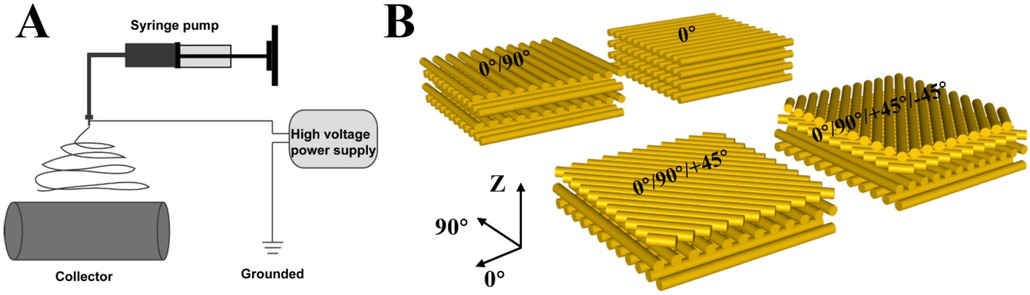
Schematic of electrospinning and four structures of PAN nanofibers: A) Schematic of electrospinning setup for collecting aligned PAN nanofibers; B) Schematic of 0∘, 0∘/90∘, 0∘/90∘/+45∘ and 0∘/90∘/+45∘/−45∘ nanofiber membranes.

Preparation and mechanical test of PAN nanofiber membrane: A) Fabricated aligned PAN nanofiber membrane; B) Tensile experiment procedure.
2.2.2 Preparation of aligned PAN nanofibers
The aligned PAN nanofibers were prepared by 12wt% PAN /DMF solution on a rotating drum with speeds from 1000 rpm to 2500rpm in the case of the same other conditions. Figure 3 shows SEM images PAN nanofibers membranes at four kinds of speed.
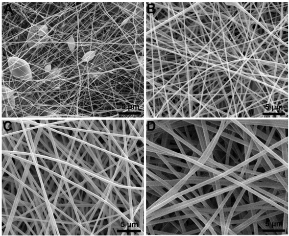
SEM images of nanofiber membranes with different concentrations; A) 8wt%; B) 10wt%; C) 12wt%; D) 14wt%.
2.2.3 Preparation of aligned PAN nanofibers of four structures
Based on the results of materials with different concentrations and rotary speeds, four kinds of fiber structures for PAN nanofibers were prepared including 0∘, 0∘/90∘, 0∘/90∘/+45∘ and 0∘/90∘/+45∘/−45∘ (Figure 1B) were prepared by 12wt% PAN/DMF solution on a rotating drum with speeds from 2500rpm in the case of the same other conditions.
2.3 Morphology characterization and tensile properties experiment
The morphology and size of all nanofiber membraneswere characterized by field emission scanning electron microscope (SEM, Quanta 250 FEG, Czech). Tensile tests of the nanofibers were performed using a material testing machine (HZ-1007E; Heng Zhun, Shanghai, People’s Republic of China). The tensile specimens were prepared by fixing the nanofiber on a stretching fixture, which the gage length L was 15 mm and the crosshead speed was 5 mm/min shown in Figure 2B. All tests were conducted in a laboratory environment at room temperature (at 20 ± 3∘C).
3 Results and discussions
3.1 Morphological analysis
3.1.1 Morphological characterization with different concentrations
The uniformity and diameter of PAN nanofiber were adjusted by concentrations of PAN/DMF solutions. Figure 3 shows SEM images of PAN nanofibers at different concentrations. It can be found that the nanofibers have uniform structure without any bead when the concentration of PAN/DMF solution increased 12wt%. The results indicated that increasing concentration lead to an increase in fiber uniformity and higher regular morphology with a decrease of droplets and beaded fibers. This phenomenon is mainly due to the surface tension decreases with the increase of solution viscosity [10]. Besides, the diameter of 8 wt%, 10 wt%, 12 wt% and 14 wt% is about 137±62, 225±61, 370±55, and 520±73 nm, respectively. It can be found that the diameters of PAN nanofibers increase approximately with the solution concentration increases. This is probably attributed to the greater stretching resistance of the solution with increasing solute content [21].
3.1.2 Morphological characterization with different rotary speeds
Electrospinning technique was utilized to prepare aligned PAN nanofibers by using a rotating drum collector that the rotary speed of collector could affect orientation of nanofibers. Figure 4 shows SEM images of PAN nanofiber membranes with concentration 12 wt% at different rotary speeds including 1000 rpm, 1500 rpm, 2000 rpm, 2500 rpm. It can be found that increasing rotary speeds lead to an increase in orientation of nanofibers, and the material exhibits the best 0∘ fiber orientation at rotational speed of 2500rpm. Figure 5A shows that the diameters of fabricated PAN nanofibers with different rotary speeds are 424±28, 208±41, 350±52, and 279±32nm respectively. Figure 5B shows the percentage of angle between nanofibers orientation and 0∘ direction. It is shown that the percentage of angle 10-0∘ of 1000 rpm, 1500 rpm, 2000 rpm, 2500 rpm is about 35%, 52%, 57%, and 73%, respectively, which further indicates that the orientation of nanofibers increases significantly with increasing rotary speed.

SEM images of aligned PAN nanofiber membranes (12wt%) at different rotary speeds: A) 1000rpm; B) 1500rpm; C) 2000rpm; D) 2500rpm.
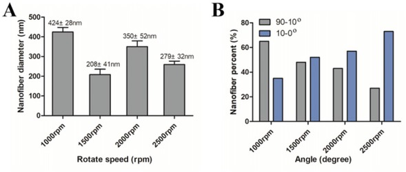
Fiber diameters and angular percentage of PAN nanofiber membranes (12wt%) at different rotary speeds: A) Diameters; B) Percentage of angle 10-0∘ and 90-10∘ with 0∘ direction.
3.1.3 Morphological characterization with different structures
Figure 6 shows SEM images of fabricated four kinds of aligned nanofiber membranes with fiber structure of 0∘, 0∘/90∘, 0∘/90∘/+45∘ and 0∘/90∘/+45∘/−45∘. It can be found that the nanofiber membrane has uniform and different fiber orientation structure. From Figure 6A, it can be found that the nanofiber membrane has good 0∘ fiber orientation structure; From Figure 6B, the material has a good fiber orientation of 0∘ and 90∘, and is formed by overlapping; From Figure 6C, the nanofiber membrane stacked together and oriented along 0∘, 90∘ and +45∘ directions; From Figure 6D, the material is oriented in four directions of 0∘, 90∘, +45∘, −45∘, and exhibits the characteristics of transverse isotropy.
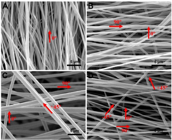
SEM images of PAN nanofiber membranes with different structures; A) 0∘ B) 0∘/90∘ C) 0∘/90∘/+45∘ D) 0∘/90∘/+45∘/−45∘.
3.2 Mechanical properties
3.2.1 Mechanical properties with different concentrations
Figure 7 shows stress-strain curves of PAN nanofiber membranes with different concentrations. It can be found that four curves show non-linear feature and the curves go up gradually with the increase of the concentration in the preliminary stage. The slope and rigidity of membranes increase with the increase of the concentration form the stress-strain curves because the fiber content and loaded capacity increase gently with the increase of the concentration. Besides, slope of stress-strain curve of 8wt% concentration is less than other three kinds of membranes. This is because the bearing capacity of 8wt% concentration membrane is affected significantly by lots of beads formed in the nanofibers.

Tensile stress-strain curves with different concentrations
From Table 1, the average tensile strengths of 8wt%, 10wt%, 12wt% and 14wt% are about 1.63±0.13MPa, 4.72±0.87MPa, 6.32±1.46MPa, 6.88±1.59MPa, respectively and the modulus are 0.069, 0.221, 0.233 and 0.298GPa. Compared with the results at 8wt%, the strength at 10wt%, 12wt% and 14wt% increased by 189.57%, 287.73% and 322.09%, respectively, and the modulus increased by 220.28%, 237.68% and 331.88%. The reason is the homogeneous and diameters of the fibers are important factors affecting the tensile properties and modulus of PAN nanofiber membranes. As the PAN concentration increases, the more homogeneous and larger diameters for fibers are obtained in the nanofiber membranes, in turn boost the tensile properties.
Mechanical properties of PAN nanofiber membranes with different parameters.
| Membranes | Parameters | Tensile strength (MPa) | Tensile Modulus (GPa) |
|---|---|---|---|
| 8 | 1.63±0.13 | 0.069 | |
| Random membranes with different | 10 | 4.72±0.87 | 0.221 |
| concentrations (wt%) | 12 | 6.32±1.46 | 0.233 |
| 14 | 6.88±1.59 | 0.298 | |
| 1000 | 25.56±3.19 | 0.401 | |
| Aligned membranes with different | 1500 | 28.78±2.99 | 0.522 |
| rotational speed (rpm) | 2000 | 30.75±3.86 | 0.988 |
| 2500 | 36.50±4.11 | 1.146 | |
| 0∘ | 36.50±4.11 | 1.146 | |
| Aligned membranes with different | 0∘/90∘ | 23.44±2.29 | 0.856 |
| directions | 0∘/90∘/+45∘ | 13.83±1.66 | 0.273 |
| 0∘/90∘/+45∘/−45 | ∘ 11.21±1.41 | 0.201 | |
3.2.2 Mechanical properties with different rotary speeds
Figure 8 shows stress-strain curves of PAN nanofiber membranes with different rotational speeds. It can be observed that the curves almost linearly increase and then the nonlinear feature near the peak, but with different slopes. When the curves have attained the peak stress, the load of all curves drops gradually, showing the plastic fracture feature. It is mainly because the 0∘ fibers in the shear plane dislocate and are torn under tensile and shear stress cou pling which causes gradual damage to the material. It can also be found that the slope and rigidity of membranes rise gradually with the increase of rotational speed. This is attributed to the improvement orientation and increased content of the fibers along the loading direction.
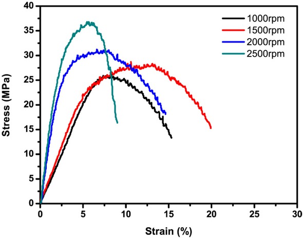
Tensile stress-strain curves with different rotary speeds
From Table 1, comparing the properties at the 1000rpm, with that elevated 1500rpm, 2000rpm and 2500rpm, the corresponding strength are 25.56±3.19, 28.78±2.99, 30.75±3.86 and 36.50±4.11MPa, and increased by 12.60%, 20.31%, 42.80%. Meanwhile, the modulus at 1000rpm, 1500rpm, 2000rpm and 2500rpm are 0.401, 0.522, 0.988 and 1.146GPa and increase 30.17%, 146.38%, 185.78%. It can be found that the strength and modulus increase significantly with increasing the rotary speeds. The reason is that the main load-carrying fibers increase in the direction of tension with the increase of rotary speed.
Therefore, the rotary speed is also an important factor affecting the tensile properties of PAN nanofiber membranes, and the performance can be improved significantly by increasing rotary speed.
3.2.3 Mechanical properties with different structures
Figure 9 shows stress-strain curves of 0∘, 0∘/90∘, 0∘/90∘/+45∘ and 0∘/90∘/+45∘/−45∘ PAN nanofiber membranes. For 0∘ and 0∘/90∘ fiber structures, the curve shows obvious linear elastic feature and exhibits brittle characteristics. This is due to the fact that there is no crimp for the fibers inside the material, and 0∘ fibers along loading direction act as the main load-bearing object which can bear load up to fracture. However, the curves for 0∘/90∘/+45∘ and 0∘/90∘/+45∘/−45∘ fiber structures show significant nonlinear transition and exhibit an obvious plastic platform which attributes to different failure mechanisms, the interfaces between the +45∘ and −45∘ fibers are the main load-bearing objects, the degradation of the matrix between the fibers increases gradually which exhibits progressive loss of stiffness. At the same time, it can be found that the curves go down gradually with the increase of the fiber orientation angle. The peak stress and the slope of the curves decreases gradually, moreover, the materials showed an extended strain response with increased fiber orientation.

Tensile stress-strain curves with different fiber structures
Table 1 shows the comparison of the tensile properties for four fiber structures. It can be found that for the 0∘ fiber structure, the tensile strength and modulus are the highest, followed by the 0∘/90∘ structure, then the 0∘/90∘/+45∘structure, and finally the 0∘/90∘/+45∘/−45∘. Tensile strength for 0∘, 0∘/90∘, 0∘/90∘/+45∘ and 0∘/90∘/+45∘/−45∘ fiber structure are 36.50±4.11, 23.44±2.29, 13.83±1.66 and 11.21±1.41MPa respectively and the modulus are 1.146, 0.856, 0.273 and 0.201GPa. Compared with the 0∘ structure, the strength decreased by 35.78%, 62.11% and 69.29%, respectively, and the modulus decreased by 25.31%, 76.18% and 82.46%. The reason is that the fibers with no crimp are the main load-bearing objects for nanofibers membrane and the number of fibers along the loading direction determines the properties of the material. However, with increasing the fiber orientation angle, the number and the effective carrying–loading capacity of fibers decreases significantly. Therefore, the fiber architecture is an important factor affecting the tensile properties of aligned nanofibers membranes which increase significantly with decreasing fiber orientation angle along the loading direction.
3.3 Fracture morphology and failure mechanism
3.3.1 Fracture morphology and failure mechanism with different concentrations
Figure 10 showed the fracture morphology of nanofiber membranes with different concentrations. From Figure 10A, at 8wt%, it can be seen that the fracture surface is L-shaped, which is affected by lots of beads of different sizes in nanofibers. Beads of different sizes cause different defects in nanofibers, and the membrane breaks at a larger defect formed L-shaped fracture under the tensile and shear stress. At 10wt%, zigzag fracture was shown in Figure 10B. Because beads and defects gradually become decrease and uniform in 10wt% nanofiber membrane, the fracture was caused at uniform beads and defects under tensile normal stress, and the nanofibers are pulled out and broken at different levels. From Figure 10C and 10D, the fracture morphology of nanofiber membranes with concentration of 12wt% and 14wt% are ductile fracture with V-shaped under the tensile and shear stress coupling due to the fact that the directions of each fiber in the membrane are different and randomly distributed. So, the main failure for non-woven nanofibers structure is shear fracture feature. The nanofibers that are parallel to loading direction are fractured under tensile normal stress, and that the nanofibers which are not parallel to the loading direction are fractured under tensile and shear stress.
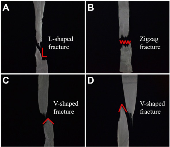
Fracture morphology of PAN nanofiber membranes with different concentrations: A) 8wt%; B) 10wt%; C) 12wt%; D) 14wt%.
3.3.2 Fracture morphology and failure mechanism with different rotary speeds
Figure 11 shows the fracture morphology of nanofiber membranes obtained at different rotary speeds. From Figure 11A, 11B and 11C, the fracture morphology of nanofiber membranes with rotary speeds 1000rpm, 1500rpm and 2000rpm are shear fracture with V-shaped. It is because each fiber in the membrane is also randomly distributed and the stress state of each fiber is different. The nanofibers that are parallel to loading direction are fractured under tensile normal stress, and that the nanofibers which are not parallel to the loading direction are fractured under tensile and shear stress, and the energy travels along the easiest path causing shear fracture. However, from Figure 11D, at 2500rpm, it can be found that the fracture becomes flush. This is mainly because the fabricated nanofibers have better orientation in 0∘ direction. The 0∘ nanofibers act as the main load-bearing object and the main failure mode is the nanofibers fracture along 0∘ direction under tensile normal stress. These fracture features also prove that the orientation of nanofibers increases significantly with increasing rotary speed and fabricated nanofibers membrane has best orientation at 2500rpm.
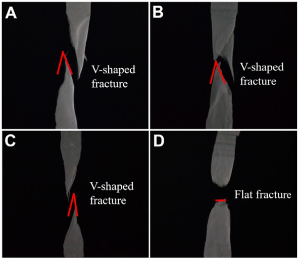
Fracture morphology of PAN nanofiber members with different rotary speeds: A) 1000rpm; B) 1500rpm; C) 2000rpm; D)2500rpm.
3.3.3 Fracture morphology and failure mechanism with different structures
Figure 12 shows the fracture morphology of nanofiber membranes possess different fiber structure with 0∘, 0∘/90∘, 0∘/90∘/+45∘ and 0∘/90∘/+45∘/−45∘. From Figure 12A, for 0∘ structure, it can be seen that the fracture is flush, the 0∘ nanofibers become loose, and there is obvious pull out under tensile normal stress, because the 0∘ nanofibers act as the load-bearing object. From Figure 7B, for 0∘/90∘ structure, the fracture for nanofibers are also flush due to the tensile normal stress, which proved that the 0∘ nanofibers still act as the main load-bearing, which is similar to the 0∘ structure. Due to the introduction of 90∘ nanofibers layer, the interlayer between the 0∘ and 90∘ nanofibers layer are bearing the coupling of tensile and shear stress which lead to the delaminating. For the 90∘ fiber layer, the nanofibers hardly bear loading and are broken, firstly the interface is damaged under the tensile stress, then the fibers are torn from the cracked matrix. From Figure 7C, for 0∘/90∘/+45∘ structure, the nanofibers appear clustering, zigzag delaminating and shear fracture can be observed. It is due to the discontinuity of stress state for different nanofiber layers and the fibers breakage is not simultaneous. On the other hand, the nanofibers in different layers have different failure mechanism. The main failure mode is the nanofibers torn along 90∘ and +45∘ direction, 0∘ nanofibers tensile fracture, as well as the fibers shear breakage. From Figure 7D, for 0∘/90∘/+45∘/−45∘ structure, the material is delaminated from the surface and the fracture are along +45∘ and −45∘ direction. The nanofibers in 0∘ layers are broken under tensile normal stress. The nanofibers in 90∘ layers are torn along fiber interface. While for nanofibers in +45∘/−45∘ layers, the main failure mode is that the +45∘/−45∘ nanofibers are torn along +45∘/−45∘ fiber interface. The main damage is in the form of interlayer delaminating, interface debonding, fibers tearing and breakage of the nanofibers.
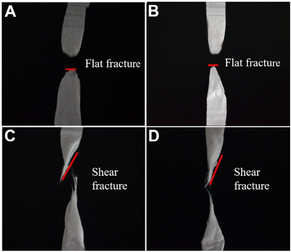
Fracture morphology of PAN nanofiber members with different structures: A) 0∘ B) 0∘/90∘ C) 0∘/90∘/+45∘ D) 0∘/90∘/+45∘/−45∘.
4 Conclusions
PAN nanofiber membranes with different concentrations, rotary speeds and four kinds of aligned with fiber orientation of 0∘, 0∘/90∘, 0∘/90∘/+45∘ and 0∘/90∘/+45∘/−45∘ were prepared. The effect of different parameters on the morphology, mechanical properties as well as failure was analyzed. The results showed that the homogeneity and tensile properties increase gradually with the increase of concentration. The orientation of nanofibers increases significantly with increasing rotary speed and fabricated nanofibers membrane has the best orientation and tensile properties at 2500rpm. Moreover, tensile stress-strain curves show significant nonlinear transition and exhibit plastic feature. In addition, the tensile properties can be affected greatly by the fiber structure and these decrease significantly with increasing the fiber orientation angle.
The fracture morphology indicated that the nanofiber membranes exhibit obvious ductile fracture characteristics. Moreover, the damage and failure patterns vary with the concentration, rotary speed and fiber structure. The main failure for non-woven nanofibers structure with different concentrations is shear fracture and that shear characteristics become more evident with increasing the concentration. With increasing the rotary speed, the failure mode changes from shear feature to flush fracture under tensile normal stress attributed to better 0∘ fiber orientation. In addition, for 0∘ fiber structure, the main failure is that the nanofibers fracture along 0∘ direction under tensile normal stress. For 0∘/90∘ structure, the failure behaves as 0∘ nanofibers are pulled out and broken while the 90∘ nanofibers are torn along the interface. For 0∘/90∘/+45∘ structure, the failure pattern is the tearing of fibers along 90∘/+45∘ fiber interface, 0∘ fibers tensile fracture as well as the fiber shear breakage. For 0∘/90∘/+45∘/−45∘ structure, the shear dominated the failure and the main damage is in the form of interlayer delaminating, interface debonding, fibers tearing and breakage of the nanofibers.
Acknowledgement
The authors acknowledge the financial supports from Excellent Young Scientist Foundation of NSFC (No.11522216); National Natural Science Foundation of China (No.11872087), Beijing Municipal Natural Science Foundation (No.2182033); Aeronautical Science Foundation of China (No.2016ZF51054). The 111 Project (No.B14009); Project of the science and Technology Commission of Military Commission (No.17-163-12-ZT-004-002-01); Foundation of Shock and Vibration of Engineering Materials and Structures Key Laboratory of Sichuan Province (No.18kfgk01). Fundamental Research Funds for the Central Universities (No.YWF-19-BJ-J-55).
References
[1] Wang S.X., Yap C.C., He J.T. et al., Electrospinning: a facile technique for fabricating functional nanofibers for environmental applications, Nanotechnology Reviews, 2016, 5, 51-73.10.1515/ntrev-2015-0065Search in Google Scholar
[2] Lin Z., Woodroof M.D., Ji L. et al., Effect of platinumsalt concentration on the electrospinning of polyacrylonitrile/platinum acetylacet- onate solution, J. Appl. Polymer Sci., 2010, 116, 895-901.10.1002/app.31616Search in Google Scholar
[3] Fan L., Ma Q., Tian J. et al., Conjugate electrospinning-fabricated nanofiber yarns simultaneously endowed with bifunctionality of magnetism and enhanced fluorescence, J. Mater. Sci., 2017, 3, 2290-2302.10.1007/s10853-017-1661-xSearch in Google Scholar
[4] Shojaie S., Rostamian M., Samadi A. et al., Electrospun electroactive nanofibers of gelatin, ligoaniline/Poly (vinyl alcohol) templates for architecting of cardiac tissue with on-demand drug release, Polymers Adv. Technol., 2019, 30, 1473-1483.10.1002/pat.4579Search in Google Scholar
[5] Frenot A., Chronakis I.S., Polymer nanofibers assembled by electrospinning, Curr. Opin. Colloid Interf. Sci., 2004, 864-875.10.1016/S1359-0294(03)00004-9Search in Google Scholar
[6] Chinnappan A., Baskar C., Baskar S. et al., An overview of electrospun nanofibers and their application in energy storage, sensors and wearable/flexible electronics, J. Mater. Chem. C., 2017, 5, 12657-12673.10.1039/C7TC03058DSearch in Google Scholar
[7] Senthil T., Anandhan S., Electrospinning of non-woven poly(styrene-co-acrylonitrile) nanofibrous webs for corro- sive chemical filtration: Process evaluation and optimization by Taguchi and multiple regression analyses, J. Electrostatics, 2015, 73, 43-55.10.1016/j.elstat.2014.10.002Search in Google Scholar
[8] Mckee M.G., Hunley M.T., Layman J.M. et al., Solution Rheological Behavior and Electrospinning of Cationic Polyelectrolytes, Macromolec„ 2006, 39, 575-583.10.1021/ma051786uSearch in Google Scholar
[9] Eda G., Liu J., Shivkumar S., Solvent effects on jet evolution during electrospinning of semi-dilute polystyrene solutions, Europ, Polymer J., 2007, 43, 1154-1167.10.1016/j.eurpolymj.2007.01.003Search in Google Scholar
[10] Veleirinho B., Rei M.F., Lopesdasilva J.A., Solvent and concentration effects on the properties of electrospun poly(ethylene terephthalate) nanofiber mats, J. Polym. Sci. Part B Polym. Phys., 2010, 46, 460-471.10.1002/polb.21380Search in Google Scholar
[11] Gee S., Johnson B., Smith A.L., Optimizing electrospinning parameters for piezoelectric PVDF nanofiber membranes, J. Membr. Sci., 2018, S0376738818304101.10.1016/j.memsci.2018.06.050Search in Google Scholar
[12] Lević S., Obradović N., Pavlović V. et al., Thermal, morphological, and mechanical properties of ethyl vanillin immobilized in polyvinyl alcohol by electrospinning process, J. Therm. Analys. Calorim., 2014, 118, 661-668.10.1007/s10973-014-4060-4Search in Google Scholar
[13] Okuzaki H., Thermo-Responsive Nanofiber Mats Fabricated by Electrospinning, Soft Actuators: Springer Japan, 2014.10.1007/978-4-431-54767-9_4Search in Google Scholar
[14] Matlock-Colangelo L., Coon B., Pitner C.L. et al., Functionalized electrospun poly(vinyl alcohol) nanofibers for on-chip concentration of E. colicells, Analytic. Bioanalytic. Chem., 2016, 408, 1327-1334.10.1007/s00216-015-9112-5Search in Google Scholar PubMed
[15] Hajiani F., Jeddi A.A.A, Gharehaghaji A.A., An investigation on the effects of twist on geometry of the electrospinning triangle and polyamide 66 nanofiber yarn strength, Fibers & Polym., 2012, 13, 244-252.10.1007/s12221-012-0244-3Search in Google Scholar
[16] Ramakrishna S., Fujihara K., Teo Wee-E., et al., An Introduction to Electrospinning and Nanofibers (Paperback), J. Eng. Fibers & Fabrics, 2008, 3, 396.Search in Google Scholar
[17] Sadrjahani M., Ravandi S.A.H., Microstructure of Heat-treated PAN Nanofibers, Fibers & Polym., 2013, 14, 1276-1282.10.1007/s12221-013-1276-zSearch in Google Scholar
[18] Qin X.H., Wan Y.Q., He J.H. et al., Effect of LiCl on electrospinning of PAN polymer solution: theoretical analysis and experimental verification, Polymer, 2004, 45, 6409-6413.10.1016/j.polymer.2004.06.031Search in Google Scholar
[19] Sharma D.K., Shen J., Li F.T., Reinforcement of Nafion into polyacrylonitrile (PAN) to fabricate them into nanofiber mats by electrospinning: characterization of enhanced mechanical and adsorption properties, RSC Advances, 2014, 4, 39110-39117.10.1039/C4RA05103CSearch in Google Scholar
[20] Li Z.Y., Zabihi O., Wang J.F. et al., Hydrophilic PAN based carbon nanofibers with improved graphitic structure and enhanced mechanical performance using ethylenediamine functionalized grapheme, RSC Adv., 2017, 7, 2621-2628.10.1039/C6RA24719ASearch in Google Scholar
[21] Hoon K.S., Gil M.B., Cheol L.S., Properties of Polyacrylonitrile/Single Wall Carbon Nanotube Composite Films Prepared in Nitric Acid, Fibers & Polym., 2005, 6, 108-112.10.1007/BF02875600Search in Google Scholar
[22] Fennessey S.F., Farris R.J., Fabrication of aligned and molecularly oriented electrospun polyacrylonitrile nanofibers and the mechanical behavior of their twisted yarns, Polymer, 2004, 45, 4217-4225.10.1016/j.polymer.2004.04.001Search in Google Scholar
[23] Sadrjahani M., Hoseini S.A., Mottaghitalab V. et al., Development and Characterization of Highly Oriented PAN Nanofiber, Brazil. J. Chem. Eng., 2010, 27, 583-589.10.1590/S0104-66322010000400010Search in Google Scholar
[24] Gu S.Y., Ren J.,Wu Q.L., Preparation and structures of electrospun PAN nanofibers as a precursor of carbon nanofibers, Synthetic Metals, 2005, 155, 157-161.10.1016/j.synthmet.2005.07.340Search in Google Scholar
© 2019 Su-dan Liu et al., published by De Gruyter
This work is licensed under the Creative Commons Attribution 4.0 Public License.
Articles in the same Issue
- Research Articles
- Investigation of rare earth upconversion fluorescent nanoparticles in biomedical field
- Carbon Nanotubes Coated Paper as Current Collectors for Secondary Li-ion Batteries
- Insight into the working wavelength of hotspot effects generated by popular nanostructures
- Novel Lead-free biocompatible piezoelectric Hydroxyapatite (HA) – BCZT (Ba0.85Ca0.15Zr0.1Ti0.9O3) nanocrystal composites for bone regeneration
- Effect of defects on the motion of carbon nanotube thermal actuator
- Dynamic mechanical behavior of nano-ZnO reinforced dental composite
- Fabrication of Ag Np-coated wetlace nonwoven fabric based on amino-terminated hyperbranched polymer
- Fractal analysis of pore structures in graphene oxide-carbon nanotube based cementitious pastes under different ultrasonication
- Effect of PVA fiber on durability of cementitious composite containing nano-SiO2
- Cr effects on the electrical contact properties of the Al2O3-Cu/15W composites
- Experimental evaluation of self-expandable metallic tracheobronchial stents
- Experimental study on the existence of nano-scale pores and the evolution of organic matter in organic-rich shale
- Mechanical characterizations of braided composite stents made of helical polyethylene terephthalate strips and NiTi wires
- Mechanical properties of boron nitride sheet with randomly distributed vacancy defects
- Fabrication, mechanical properties and failure mechanism of random and aligned nanofiber membrane with different parameters
- Micro- structure and rheological properties of graphene oxide rubber asphalt
- First-principles calculations of mechanical and thermodynamic properties of tungsten-based alloy
- Adsorption performance of hydrophobic/hydrophilic silica aerogel for low concentration organic pollutant in aqueous solution
- Preparation of spherical aminopropyl-functionalized MCM-41 and its application in removal of Pb(II) ion from aqueous solution
- Electrical conductivity anisotropy of copper matrix composites reinforced with SiC whiskers
- Miniature on-fiber extrinsic Fabry-Perot interferometric vibration sensors based on micro-cantilever beam
- Electric-field assisted growth and mechanical bactericidal performance of ZnO nanoarrays with gradient morphologies
- Flexural behavior and mechanical model of aluminum alloy mortise-and-tenon T-joints for electric vehicle
- Synthesis of nano zirconium oxide and its application in dentistry
- Surface modification of nano-sized carbon black for reinforcement of rubber
- Temperature-dependent negative Poisson’s ratio of monolayer graphene: Prediction from molecular dynamics simulations
- Finite element nonlinear transient modelling of carbon nanotubes reinforced fiber/polymer composite spherical shells with a cutout
- Preparation of low-permittivity K2O–B2O3–SiO2–Al2O3 composites without the addition of glass
- Large amplitude vibration of doubly curved FG-GRC laminated panels in thermal environments
- Enhanced flexural properties of aramid fiber/epoxy composites by graphene oxide
- Correlation between electrochemical performance degradation and catalyst structural parameters on polymer electrolyte membrane fuel cell
- Materials characterization of advanced fillers for composites engineering applications
- Humic acid assisted stabilization of dispersed single-walled carbon nanotubes in cementitious composites
- Test on axial compression performance of nano-silica concrete-filled angle steel reinforced GFRP tubular column
- Multi-scale modeling of the lamellar unit of arterial media
- The multiscale enhancement of mechanical properties of 3D MWK composites via poly(oxypropylene) diamines and GO nanoparticles
- Mechanical properties of circular nano-silica concrete filled stainless steel tube stub columns after being exposed to freezing and thawing
- Arc erosion behavior of TiB2/Cu composites with single-scale and dual-scale TiB2 particles
- Yb3+-containing chitosan hydrogels induce B-16 melanoma cell anoikis via a Fak-dependent pathway
- Template-free synthesis of Se-nanorods-rGO nanocomposite for application in supercapacitors
- Effect of graphene oxide on chloride penetration resistance of recycled concrete
- Bending resistance of PVA fiber reinforced cementitious composites containing nano-SiO2
- Review Articles
- Recent development of Supercapacitor Electrode Based on Carbon Materials
- Mechanical contribution of vascular smooth muscle cells in the tunica media of artery
- Applications of polymer-based nanoparticles in vaccine field
- Toxicity of metallic nanoparticles in the central nervous system
- Parameter control and concentration analysis of graphene colloids prepared by electric spark discharge method
- A critique on multi-jet electrospinning: State of the art and future outlook
- Electrospun cellulose acetate nanofibers and Au@AgNPs for antimicrobial activity - A mini review
- Recent progress in supercapacitors based on the advanced carbon electrodes
- Recent progress in shape memory polymer composites: methods, properties, applications and prospects
- In situ capabilities of Small Angle X-ray Scattering
- Review of nano-phase effects in high strength and conductivity copper alloys
- Progress and challenges in p-type oxide-based thin film transistors
- Advanced materials for flexible solar cell applications
- Phenylboronic acid-decorated polymeric nanomaterials for advanced bio-application
- The effect of nano-SiO2 on concrete properties: a review
- A brief review for fluorinated carbon: synthesis, properties and applications
- A review on the mechanical properties for thin film and block structure characterised by using nanoscratch test
- Cotton fibres functionalized with plasmonic nanoparticles to promote the destruction of harmful molecules: an overview