Computer technology of the thermal stress state and fatigue life analysis of turbine engine exhaust support frames
-
A. A. Ryabov


Abstract
An advanced computer technology of the thermal stress state and fatigue life analysis of turbine engine exhaust support frames based on the use of licensed engineering analysis software, as well as some specialized home codes are presented in the paper. The developed technology allows perform simulations for the full model of the structure, not only for the typical fragments models, and increase an accuracy of calculations and significantly reduce a design time.
1 Introduction
ESF (exhaust support frame) are one of the critical and most loaded part of the gas-turbine engines. During operation, these units are exposed by a complex combination of thermal stress due to the high-temperature flow of the fuel combustion products and mechanical loads. Interaction with high-temperature flow leads to uneven heating of the structure, which causes temperature stresses acting in conjunction with stresses from mechanical loads. The ESF structure must be deformed elastically and meet the specified requirements for the fatigue life. Due to the complex geometry and the high cost of manufacturing experimental studies of ESF strength under normal operating conditions are very difficult and much expensive. Therefore, the numerical studies of thermal state, strength and fatigue life are an integral part of a design process and certification of the ESF construction [1]. At the stage of the ESF design considerable attention should be paid also to reduction of its metal content (weight optimization). In the process of construction optimization a number of design versions are examined, which requires large labor expenses for the development of corresponding grids and conducting of numerical calculations. This stimulates progress of numerical methods and computer technologies able to essentially increase an accuracy of numerical modeling of thermal and stress states of gas-turbine units and to reduce design time [2, 3, 4, 5, 6, 7, 8, 9, 10, 11].
A description of computer technology of the thermal stress state analysis of turbine engine ESF is presented in [4]. A main feature of the technology is a simulation of the thermal state for certain typical fragments of the ESF, and then on a basis of the obtained results automatically formed a full temperature field. This approach to the solution of a problem was applied mainly due to the functional limitations of the software in terms of radiant heat transfer. In this paper, an improved technology is presented with an ability to perform calculations on the full model of a structure. This technology is based on the combined use of the following software:
STAR-CCM+ – to create of FVM, FEM and calculation of thermal and stress states by the finite element and finite volume methods [5];
ABAQUS / ANSYS – to calculate of the thermal stress state by the finite element method.
It is important to note that, if it’s necessary to optimize individual zones of the structure or a comparative analysis of the thermal stress for several variants, it is effective to use only STAR-CCM+ in accordance with the calculation algorithm shown schematically in Figure 1. Given the high efficiency of grid generation in STAR-CCM+, the proposed approach can significantly reduce the overall time to conduct the calculated optimization [3].
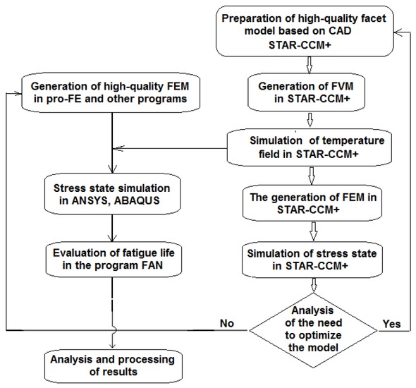
A block diagram of the calculation process using the presented technology
Below is a description of the main stages of the presented computer technology.
2 Generation of Discrete Models
The development of computational models is a responsible and one of the most important stages of the numerical simulation. An accuracy of the solution depends on the quality of the constructed models, so in the presented technology is paid special attention to this stage of work.
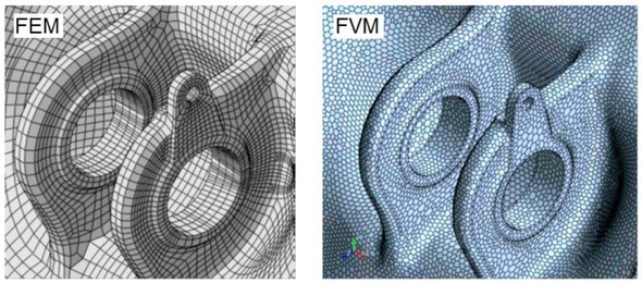
Automatic FVM and FEM generation is performed in parallel mode in STAR-CCM+ (Siemens PLM Software). The time required for automatic generation of mixed-type FE-grids and FV-grids in STAR- CCM+ is about two orders of magnitude lower than for the development of a higher-quality FE- grids consisting of 100% hexahedrons in other software packages [3, 4, 5].
To build a high-quality FE-grids preprocessor pro-FE is used. The use of pro-FE makes it possible to effectively generate the grids, especially in areas with complex geometric features, and to ensure a good quality due to the possibilities of parametric rearrangement and efficient smoothing algorithms. To reduce the time of grid generation, automate the execution of repetitive blocks of commands, as well as the effective formation of BC on large-dimensional grids, the "adaptation" of pro-FE capabilities is performed to the construction of complex models through the development of special "panels", macros and programs [8]. Fig. 1 shows a block diagram of the FEM generation algorithm based on these software tools.
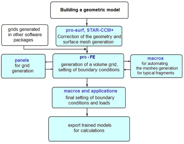
General block diagram of the algorithm for generation of FEM
The optimal density of the FE-grids is revealed on a basis of the convergence research of the different grids, prepared by the path of successive automatic thickening in local areas with a change of element sizes (Figure 3). Numerical attempts show that an optimal FEM should be at least ~1.6 million isoparametric elements, and the FVM for thermal state analysis - at least ~ 4÷5 millions cells (Figure 4).
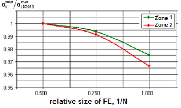
The curves of results convergence by refining mesh
Fragments of Discrete Models
The computer model includes ESF, as well as the adjacent additional elements, which allows:
to avoid the need to form additional BC in the model at the places of parts connection;
to improve the accuracy of stress state calculation due to accurate simulation of conditions of fixing and taking into account the compliance of additional elements;
to improve the accuracy of the thermal state simulation by taking into account the radiant heat exchange with the surrounding parts.
Special macros and programs are used to efficiently form boundary conditions and loads on high-dimensional computational models [4, 8].
3 Thermal Analysis
Typically, the simulation of a thermal state of ESF is carried out for the most "heavy" stationary thermal modes of an engine and for the conditions of unsteady loading on the flight cycle. STAR-CCM+ allows to simulate the thermal state of the ESF taking into account the radiant heat transfer on the whole model, if there are enough computational resources. For example, to perform unsteady calculations on FVM~ 10 million polyhedral cells at an acceptable time, 70-80 IBM cluster cores with the following parameters of counting nodes are required: 3 GHz, 64 GB.
The boundary conditions of convective heat transfer with the external environment are formed in the form of:
Model surface distributions over a set of regions with their boundaries and dimensions;
Tables and text files with heat transfer coefficients and ambient temperatures for regions.
The formation of boundary conditions is performed automatically by special macros.
The results of calculations for stationary modes are presented in a form of temperature distribution and temperature change curves for a height of an inner surface of typical racks. For unsteady modes the temperature fields in the given time sections of a flight cycle and the graphs of temperature versus time in the control points or individual fragments of the structure are determined (Figure 5).
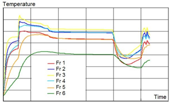
The graphs of temperature versus time in the individual fragments of the structure
The temperature distribution is automatically interpolated to all FEM nodes in STAR-CCM+ and written to the special format files for transfer to ABAQUS / ANSYS.
The acceptability of this technology has been confirmed experimentally.
4 Thermal Stress Analysis
The analysis of the ESF fatigue life under conditions of unsteady loading on the flight cycle determines a detailed study of the stress state kinetics in their most stressed zones. Such calculations can be performed in ABAQUS or ANSYS, which have all the necessary functionality [3, 4]. For example, in some cases, the calculations are carried out taking into account the nonlinearity of the material in accordance with any theory of plasticity [13, 14]. A plasticity model with isotropic hardening of the material is used often and dependence of material properties via temperature is also taken into account.
Different methods of solving of algebraic equations systems are used for calculations on different computing platforms. The choice of the solution method is determined, first of all, by the dimensionality of the computational model and the RAM [4]. Running tasks on the solution is performed by macros.
Simulation of thermal stress state of the structure is performed in the given time points of the flight cycle to determine the most stressed areas, getting the dependences of stresses and strains via time to analyze safety factors of the structure. In addition, the values of radial and axial displacements averaged values of radial forces are determined in control points and cross sections on the flanges. Special macros are used to automate the results processing [4].
The results are presented as a distribution of equivalent stresses, total and plastic deformations, as well as tables with the values of the components of equivalent stress and total strain tensors in the critical zones for the selected time sections. The changes in the values of the components of the total strain and stress tensors, the main deformations in the critical zones are analyzed (Figure 6).
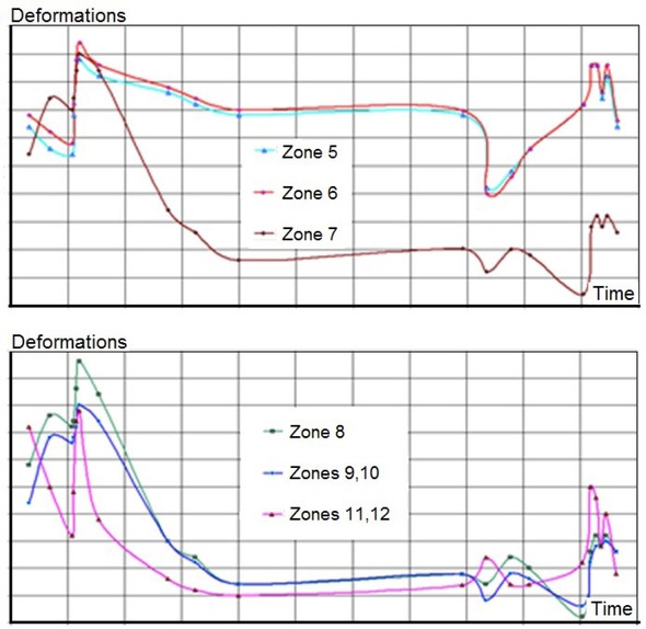
The dependence of the intensity of total deformations in the critical zones of one of the EF on the flight cycle
As previously noted, if it is necessary to perform calculations for several design options, calculations are performed in STAR-CCM+. For efficient application of STAR-CCM+ it seems to be reasonable to use two-stage technique for every design option. At the first stage, stress-strain analysis is performed on the base of a coarse mesh of relatively low dimensionality (approximately 2 million cells) in order to define the most stressed areas. At the second stage, series of local mesh refinements is performed in these areas (the refined mesh includes about 8 million cells) up to the series convergence (Figure 7). In this case, the iterative solution of the system of equations can be accelerated in several times, using as an initial approximation the solution obtained on the "coarse" grid.
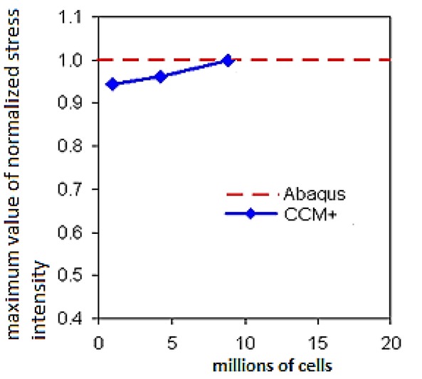
The convergence of the calculation results in STAR-CCM+ during the local mesh refinements
5 Fatigue Life Calculation
When the engine is operated in critical areas of the ESF fatigue damage will accumulate. Reaching of the critical damage values leads to the emergence of macro-cracks, as the limit state at the first stage of fatigue failure.
In the simplest case, the calculation of the fatigue life of the ESF is performed using only the low-cycle fatigue curves, obtained at different temperatures and types of stress state. In this case, it is impossible to take into account the quasi-static damage of the material in the most loaded areas. In general, the cyclic deformation diagrams and long-term strength curves with the corresponding loading regime should be known [15, 16, 17].
To perform a more accurate calculation of fatigue life, the shape of the deformation cycle in the critical zones must be taken into account. For this purpose, a mode of material loading in the most stressed zones, obtained as a result of calculations, is schematized. After schematization, the amplitudes of deformations in the cycle are distinguished, which have the main influence on the accumulation of fatigue damage. As a result of schematization, we obtain data on the repeatability of the amplitudes of the full deformations of different levels in the cycle, as well as the accumulated number of sub-cycles. Schematization of the cycle is carried out by the method of "full cycles" [20, 21]. A calculation of fatigue life material in critical zones is based on the corrected hypothesis of linear summation of fatigue damage, which has the strength condition in form [18, 19]:
where Ni* - the number of cycles of repetition of the amplitude σai for the entire service life;
Ni - the number of cycles on the fatigue curve, corresponding to the amplitude σai;
mijk – number of different levels of stress amplitudes (sub-cycles).
σ−1d – the fatigue limit of the material of the part.
The summands corresponding to the amplitudes of conditionally elastic stresses σai < σ−1d should not be included in the sum, since for them the fatigue life Ni is equal to infinity1.
Instead of the fatigue limit of the sample material σ−1, the fatigue limit of the part σ1d defined is considered.
In engineering practice, the following formula is widely used to determine the coefficient KD:
where Kdσ - scale factor; KF - factor affecting the quality of surface treatment; Kσ - stress concentration factor:
It is obvious that
where λ – the number of flight cycles that the material is able to withstand in the area under consideration until the formation of macroscopic cracks. Then the strength condition can be represented as
Thus, the solution of the problem of determining the EF fatigue life is reduced to the calculation of a number of flight cycles to the formation of macroscopic cracks for each of most loaded zones.
The automate and improve an accuracy of calculations, the described calculation algorithm is implemented in the program FAN. The block diagram of the calculation algorithm is shown in Figure 8. The program provides the user with an ability to select property values for many of the most common materials from database or to set values manually.
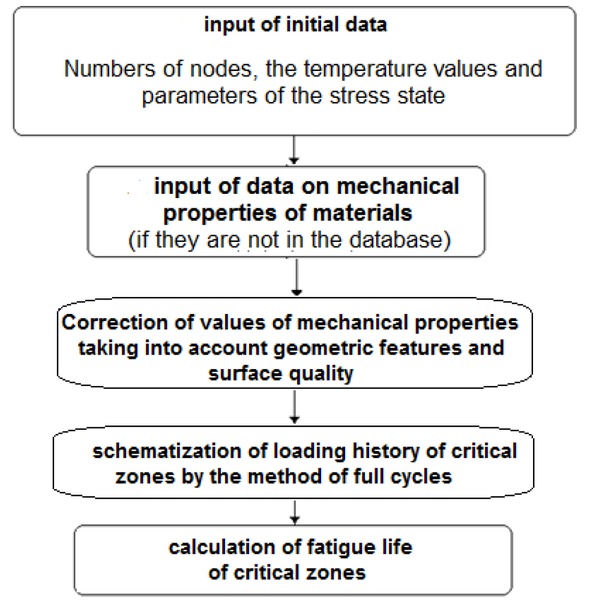
The block diagram of the calculation algorithm
After the program operation, a table is displayed, in which the specified numbers of the nodes of the computational model, the values of the corresponding temperature and the results of calculations are specified – the durability value for the critical zones in flight cycles.
Fatigue analysis and fatigue damage models (and failure criteria) could also be implemented in simple fiber-based finite element platforms (see e.g. [22]). This would speed up the process and make approaches such as those applicable to large-scale oriented analysis.
It should be noted that the total number of cycles before the failure of the ESF under cyclic thermal loading is defined as the sum of the number of cycles at the stage of fatigue crack nucleation calculated using the above approaches, and the number of cycles at the stage of crack propagation to critical dimensions determined by the Paris-Makhutov equation. In accordance with the described technology, the durability of the ESF is determined only by the moment of formation of macroscopic cracks within the most stressed zones.
6 Conclusions
A new technology is developed for simulating the thermal stress state and fatigue life analysis of ESF based on the use of modern licensed software and allows carry out calculations for all complex structures, improve the accuracy of the calculations and significantly reduce the effort in designing and optimizing. Targets to define accuracy calculations could be identified with experimentaltesting, if or when results are available.
Numerical attempts carried out on the basis of the developed technology show that the optimal finite element model for stress state analysis should be at least ~1.6 million elements, and the finite volume model for thermal state analysis - at least ~ 4 - 5 million cells.
The developed technology was used to calculate the thermal stress state and fatigue life of the ESF for new engines and is currently used in similar calculations for other complex components of engines.
References
[1] Mashinostroenie. Encyclopedia. T.4-21. Aviation engines. B.3 (2010) V.A. Skibin (in Russian.).Suche in Google Scholar
[2] Muravchenko F.M. Actual problems of dynamic strength and reliability of aviation engines // Vibration in Engineering and Technologies. – 2004. -#6. – S.2-4. (in Russian).Suche in Google Scholar
[3] Ryabov A.A., Rechkin V.N., Gelezov S.A., Shmotin Yu.N., Veselov A.V., Mueller A.. Analysis of Efficiency of computing Technology for Modelling Thermal-Stress State of GTE Exhaust Support Frame // Electronic Journal «Trudy MAI» http://www.mai.ru/science/trudy/ 2010, Nr.41. (in Russian).Suche in Google Scholar
[4] Rechkin V.N. Development and Application of Computing Technology of Numerical Investigations of Stress, Stability and Low Cyclic Fatigue of Complicated Elements of Aviation Engines.: Dissertation ...of candidate of Technical Science: 05.07.05 / Rechkin Vadim Nicolaevich; [MAI].- Sarov, 2012.- 167 s.: il. RGB OD, 61 12-5/3931. (in Russian.).Suche in Google Scholar
[5] Ryabov A.A., Rechkin V.N., Kudryavtsev A.Yu., Shmotin Yu.N., Bondyugin M.V.. Comparative Analysis of Efficiency of Computing Technology for Modelling of Thermal State of GTE Exhaust Support Frame // Scientific and Practical Conference «Aviation Engines of XXI Century ». 2015. Moscow. Abstracts. (in Russian.).Suche in Google Scholar
[6] Ryabov A.A., Romanov V.I., Rechkin V.N., Shmotin Yu.N., Veselov A.V. Application of Modern Computing Technology for Investigation of Stress, Stability and Fatigue of GTE Exhaust Support Frame // 8th International Conference «Aviation and Cosmonautics - 2009». Proceedings. – M.: MAI-Print, 2009. (in Russian).Suche in Google Scholar
[7] Ferguson S. Flow, Thermal, Stress. Simulation in STAR-CD v4 // Dynamics. – 2007. – #27. – P.4-5.Suche in Google Scholar
[8] Robb D. Eliminating heat stress failures in industrial turbines // Dynamics. – 2009. – issue 3.01. – P.45-48.Suche in Google Scholar
[9] Michaylov A.L., Osadhiy N.V. Methodological Aspects Mathematical FEM Modelling of Volume Stress State of GTE Exhaust Support Frames // Reports of III-th Russian Conference «Methods and Software of Stress Analysis Calculations. M.: FGUP NIKIET, 2005. – S.43-51. (in Russian).Suche in Google Scholar
[10] Karimbaev K.D., Servetnik A.N. Low-Cycle Fatigue Calculation of Gas Turbine Engine Disks under Flight Cycle Conditions // Problems of Strength. - 2009. - Nr.1.- P.129-133.10.1007/s11223-009-9105-8Suche in Google Scholar
[11] Velikanova N.P., Kiselev A.S. Determination of Static Strength of Turbine Blades of Aviation GTE and Comparison of Different Methods of Calculations // Izv. vuzov. Aviacionnaya tehnika. – 2009. - Nr.3. – S.36-39. (in Russian).Suche in Google Scholar
[12] Ryabov A.A., Rechkin V.N. Computing Technology of Effective Generation Numerical Models for Complex Units of Aviation Engines // Scientific and practical conference «Innovations in Aviation and Cosmonautics - 2012». Moscow. Abstracts. - M.: «Print-salon».(in Russian).Suche in Google Scholar
[13] Kachanov L.M. Background of Theory of Plasticity. - M.: Nauka, 1969. – 420p. (in Russian).Suche in Google Scholar
[14] Filin A.P. Applied Solids Mechanics. T.1. - M.: Nauka, 1975. – 832s. (in Russian).Suche in Google Scholar
[15] Gusenkov A.P., Kotov P.I. Long and Short Life of Non-isothermal Fatigue of Structural Elements. – M.: Mashinostroenie, 1988. – 264p. (in Russian).Suche in Google Scholar
[16] Gusenkov A.P., Kotov P.I. Short Life Fatigue under Non-isothermal Loading / A.P. Gusenkov, P.I. Kotov. - M.: Mashinostroenie, 1983. - 242 p. (in Russian).Suche in Google Scholar
[17] Rebyakov Yu.N., Gohfeld D.S., Sadakov O.S. Cyclic Hardening due to Deformation Pre-History and Estimation of Durability // Reports of Symposium. “Short Life Fatigue”.- Kishinev, 1991. (in Russian).Suche in Google Scholar
[18] Strigalo V.A. Cyclic Strength and Creep of Metals under Short Cyclic Loading with Low and High Temperatures.– K.: «Nauk. dumka», 1978. – 238s. (in Russian).Suche in Google Scholar
[19] Kogaev V.P., Mahutov N.A., Gusenkov A.P. Stress and Fatigue Analysis Calculations of Details of Machines and Constructions – M.: Mashinostroenie, 1985. – 224p (in Russian).Suche in Google Scholar
[20] Poroshin V.B. Influence of Form of Deformation Cycle onto Damage Collection Process under Different Types of Short Time Cyclic Loading with Pauses // Strength Problems.- 1988.- N 1. - S.38-43. (in Russ.).Suche in Google Scholar
[21] Bagmutov V.P., Savkin A.N. Resource Estimation of Machine Details under Block Loading // Problems of Machinu-building and Reliability of Machines.- 2007. - Nr.2. – S. 116-122. (in Russian).10.3103/S1052618807020185Suche in Google Scholar
[22] Vela R.J.M, Brunesi E., Nascimbene R. Floor spectra estimates for an industrial special concentrically braced frame structure. Journal of Pressure Vessel Technology 2019; 141(1),010909.10.1115/1.4041285Suche in Google Scholar
© 2019 A. A. Ryabov et al., published by De Gruyter
This work is licensed under the Creative Commons Attribution 4.0 International License.
Artikel in diesem Heft
- Regular Article
- Exploring conditions and usefulness of UAVs in the BRAIN Massive Inspections Protocol
- A hybrid approach for solving multi-mode resource-constrained project scheduling problem in construction
- Identification of geodetic risk factors occurring at the construction project preparation stage
- Multicriteria comparative analysis of pillars strengthening of the historic building
- Methods of habitat reports’ evaluation
- Effect of material and technological factors on the properties of cement-lime mortars and mortars with plasticizing admixture
- Management of Innovation Ecosystems Based on Six Sigma Business Scorecard
- On a Stochastic Regularization Technique for Ill-Conditioned Linear Systems
- Dynamic safety system for collaboration of operators and industrial robots
- Assessment of Decentralized Electricity Production from Hybrid Renewable Energy Sources for Sustainable Energy Development in Nigeria
- Seasonal evaluation of surface water quality at the Tamanduá stream watershed (Aparecida de Goiânia, Goiás, Brazil) using the Water Quality Index
- EFQM model implementation in a Portuguese Higher Education Institution
- Assessment of direct and indirect effects of building developments on the environment
- Accelerated Aging of WPCs Based on Polypropylene and Plywood Production Residues
- Analysis of the Cost of a Building’s Life Cycle in a Probabilistic Approach
- Implementation of Web Services for Data Integration to Improve Performance in The Processing Loan Approval
- Rehabilitation of buildings as an alternative to sustainability in Brazilian constructions
- Synthesis Conditions for LPV Controller with Input Covariance Constraints
- Procurement management in construction: study of Czech municipalities
- Contractor’s bid pricing strategy: a model with correlation among competitors’ prices
- Control of construction projects using the Earned Value Method - case study
- Model supporting decisions on renovation and modernization of public utility buildings
- Cements with calcareous fly ash as component of low clinker eco-self compacting concrete
- Failure Analysis of Super Hard End Mill HSS-Co
- Simulation model for resource-constrained construction project
- Getting efficient choices in buildings by using Genetic Algorithms: Assessment & validation
- Analysis of renewable energy use in single-family housing
- Modeling of the harmonization method for executing a multi-unit construction project
- Effect of foam glass granules fillers modification of lime-sand products on their microstructure
- Volume Optimization of Solid Waste Landfill Using Voronoi Diagram Geometry
- Analysis of occupational accidents in the construction industry with regards to selected time parameters
- Bill of quantities and quantity survey of construction works of renovated buildings - case study
- Cooperation of the PTFE sealing ring with the steel ball of the valve subjected to durability test
- Analytical model assessing the effect of increased traffic flow intensities on the road administration, maintenance and lifetime
- Quartz bentonite sandmix in sand-lime products
- The Issue of a Transport Mode Choice from the Perspective of Enterprise Logistics
- Analysis of workplace injuries in Slovakian state forestry enterprises
- Research into Customer Preferences of Potential Buyers of Simple Wood-based Houses for the Purpose of Using the Target Costing
- Proposal of the Inventory Management Automatic Identification System in the Manufacturing Enterprise Applying the Multi-criteria Analysis Methods
- Hyperboloid offset surface in the architecture and construction industry
- Analysis of the preparatory phase of a construction investment in the area covered by revitalization
- The selection of sealing technologies of the subsoil and hydrotechnical structures and quality assurance
- Impact of high temperature drying process on beech wood containing tension wood
- Prediction of Strength of Remixed Concrete by Application of Orthogonal Decomposition, Neural Analysis and Regression Analysis
- Modelling a production process using a Sankey diagram and Computerized Relative Allocation of Facilities Technique (CRAFT)
- The feasibility of using a low-cost depth camera for 3D scanning in mass customization
- Urban Water Infrastructure Asset Management Plan: Case Study
- Evaluation the effect of lime on the plastic and hardened properties of cement mortar and quantified using Vipulanandan model
- Uplift and Settlement Prediction Model of Marine Clay Soil e Integrated with Polyurethane Foam
- IoT Applications in Wind Energy Conversion Systems
- A new method for graph stream summarization based on both the structure and concepts
- “Zhores” — Petaflops supercomputer for data-driven modeling, machine learning and artificial intelligence installed in Skolkovo Institute of Science and Technology
- Economic Disposal Quantity of Leftovers kept in storage: a Monte Carlo simulation method
- Computer technology of the thermal stress state and fatigue life analysis of turbine engine exhaust support frames
- Statistical model used to assessment the sulphate resistance of mortars with fly ashes
- Application of organization goal-oriented requirement engineering (OGORE) methods in erp-based company business processes
- Influence of Sand Size on Mechanical Properties of Fiber Reinforced Polymer Concrete
- Architecture For Automation System Metrics Collection, Visualization and Data Engineering – HAMK Sheet Metal Center Building Automation Case Study
- Optimization of shape memory alloy braces for concentrically braced steel braced frames
- Topical Issue Modern Manufacturing Technologies
- Feasibility Study of Microneedle Fabrication from a thin Nitinol Wire Using a CW Single-Mode Fiber Laser
- Topical Issue: Progress in area of the flow machines and devices
- Analysis of the influence of a stator type modification on the performance of a pump with a hole impeller
- Investigations of drilled and multi-piped impellers cavitation performance
- The novel solution of ball valve with replaceable orifice. Numerical and field tests
- The flow deteriorations in course of the partial load operation of the middle specific speed Francis turbine
- Numerical analysis of temperature distribution in a brush seal with thermo-regulating bimetal elements
- A new solution of the semi-metallic gasket increasing tightness level
- Design and analysis of the flange-bolted joint with respect to required tightness and strength
- Special Issue: Actual trends in logistics and industrial engineering
- Intelligent programming of robotic flange production by means of CAM programming
- Static testing evaluation of pipe conveyor belt for different tensioning forces
- Design of clamping structure for material flow monitor of pipe conveyors
- Risk Minimisation in Integrated Supply Chains
- Use of simulation model for measurement of MilkRun system performance
- A simulation model for the need for intra-plant transport operation planning by AGV
- Operative production planning utilising quantitative forecasting and Monte Carlo simulations
- Monitoring bulk material pressure on bottom of storage using DEM
- Calibration of Transducers and of a Coil Compression Spring Constant on the Testing Equipment Simulating the Process of a Pallet Positioning in a Rack Cell
- Design of evaluation tool used to improve the production process
- Planning of Optimal Capacity for the Middle-Sized Storage Using a Mathematical Model
- Experimental assessment of the static stiffness of machine parts and structures by changing the magnitude of the hysteresis as a function of loading
- The evaluation of the production of the shaped part using the workshop programming method on the two-spindle multi-axis CTX alpha 500 lathe
- Numerical Modeling of p-v-T Rheological Equation Coefficients for Polypropylene with Variable Chalk Content
- Current options in the life cycle assessment of additive manufacturing products
- Ideal mathematical model of shock compression and shock expansion
- Use of simulation by modelling of conveyor belt contact forces