Uplift and Settlement Prediction Model of Marine Clay Soil e Integrated with Polyurethane Foam
-
D.C. Lat
 ,
I.B.M. Jais
,
I.B.M. Jais

Abstract
Polyurethane (PU) foam is a lightweight material that can be used efficiently as a ground improvement method in solving excessive and differential settlement of soil foundation mainly for infrastructures such as road, highway and parking spaces. The ground improvement method is done by excavation and removal of soft soil at shallow depth and replacement with lightweight PU foam slab. This study is done to simulate the model of marine clay soil integrated with polyurethane foam using finite element method (FEM) PLAXIS 2D for prediction of settlement behavior and uplift effect due to polyurethane foam mitigation method. Model of soft clay foundation stabilized with PU foam slab with variation in thickness and overburden loads were analyzed. Results from FEM exhibited the same trend as the results of the analytical method whereby PU foam has successfully reduced the amount of settlement significantly. With the increase in PU foam thickness, the settlement is reduced, nonetheless the uplift pressure starts to increase beyond the line of effective thickness. PU foam design chart has been produced for practical application in order to adopt the effective thickness of PU foam within tolerable settlement value and uplift pressure with respect to different overburden loads for ground improvement works.
1 Introduction
Excessive post construction and differential settlement frequently cause catastrophic failure to the soil foundation of civil infrastructures, therefore immediate rectification works of the soil foundation are needed. The delay in rectification works might turn the minor defect into serious defect that may endanger the safety of the people and increase the remedial cost. Most of the conventional remedial measures available apply additional load to the existing soil which increases consolidation settlement. Alternative remedial measure is using lightweight PU foam which is produced by exothermic reactions between alcohols with two or more reactive hydroxyl (–OH) groups per molecule (diols, triols, polyols) and isocyanates that have more than one reactive isocyanate group (–NCO) per molecule (diisocyanates, polyisocyanates) [1,2].
Both chemicals are mixed in a rectangular-shaped foamwork. Reaction occurs between both chemicals, then expands and hardens in a few minutes to produce a PU foam slab. The soft soil is excavated at shallow depth and replaced with the PU foam slab. Due to its lightweight properties, the excessive settlement problem can be overcome by this remedial measure as the overburden stress due to soft soil is reduced and the hydrostatic uplift assists the PU foam slab to float in order to provide stable foundation for infrastructure. However, the thickness of the foam is an important consideration [3]. Major concern for lightweight materials as a ground improvement application is the buoyancy of the materials [4]. The upward buoyant force may cause excessive uplift of the infrastructure which might jeopardize the stability of the infrastructure hence cause structural failure. However, the upward buoyant force that causes the excessive uplift can be avoided by controlling the thickness of the foam based on the existing overburden pressure.
Expanded Polystyrene (EPS) on the other hand is a lightweight cellular plastic material consisting of small hollow spherical balls. Densities of EPS is lower than the densities of PU whereby the higher the density of both EPS and PU, the more expensive the foam will be. About 98% of EPS material is air which makes EPS very light,
thus gives it a great buoyancy. EPS has been used to keep many products afloat for decades. Due to lightweight of both materials, it is very suitable to combat ground settlement problem [13]. Several reports have appeared in the literature on the susceptibility of PU to fungal attack [14, 15, 16, 17, 18]. These studies revealed that polyether PU is moderately resistant to fungal and microbial. Polyurethane is better defined as a thermal-set plastic, which means this product would not melt at temperatures below 1000 degrees. EPS on the other hand will soften at 180 degrees and would melt at 240 degrees, therefore it is a combustible material. Polyurethane provides excellent adhesive compare to EPS [19]. Other than that, PU can be injected through a small hole and fill the void underneath the slab without major excavation and disruption to the existing infrastructure.
There were a few failure cases of embankment founded on lightweight geofoam reported by Frydelund [5] due to buoyancy. Unpredicted rainfall and the rise of flood level in Oslo, Norway in 1987 caused first lightweight geofoam namely Expanded Polystyrene (EPS) fill built in 1972 floated off due to the initial design prediction made in 1972 was 0.85 m lower than the flood level occurred in 1987. Another incident occurred in Thailand whereby the unexpected water level washed away the road fill with lightweight geofoam. The study by Stephen [4] revealed that the geofoam was potentially vulnerable to uplift movement during periods of flooding due to an inadequate weight of the earth fill above the geofoam. The low amount of compacted earth fill provided low resistance against uplift due to buoyancy. Buoyancy turned out to be the primary controlling factor in determining the most cost-effective redesign alternative and corresponding factor of safety against uplift [6]. The use of waste materials as a lightweight fill such as foamglass, sawdust and bark residue, foamed concrete, lightweight clay aggregate and shredded tyres has been discussed by Frydelund and Aaboer [7]. Variety of techniques have been reported to reduce the embankment deformation and prevent potential stability failure. These methods including improving the fill properties using lightweight fill, excavation and replacement, pile embankment and geosynthetic reinforcement [8,9]. Study by Stuedlein and Negussey [10] is on the application of lightweight materials using EPS geofoam on bridge supported on piles whereby the approach fills experienced settlements ranging from 20 cm to 30 cm annually, requiring constant grade maintenance. Ghani [11] has carried out a study on the use of polyurethane for road flood damage control. Mohamed Jais [12] has undertaken the case study on road maintenance experience using polyurethane (PU) foam injection system. The materials have successfully reduced the settlement of soil and expedited the construction works on soft subsoil.
The soft soil properties of high compressibility and low permeability introduce large embankment settlement over the time as excess pore pressure dissipates and embankment loading is applied [20, 21, 22]. For predicting the behaviour of embankment on soft ground, one of the key points is to simulate the consolidation process. The consolidation rate is mainly influenced by the foundation soil permeability. The permeability of soft ground varies during the loading and consolidation process and significant changes occur before and after the soil yields [23]. Available numerical methods for calculating an embankment settlement are the layer-wise summation method (LSM), empirical formulation method, finite element method (FEM) etc. Of these methods, FEM is the most powerful numerical tool for solving complicated 2D or 3D consolidation settlement problems. It can handle arbitrary boundary conditions, different loading schemes and it considers the coupling effects of loading and soil consolidation [24]. This study is done to investigate the relationship between the uplift and settlement of soil with variation of overburden load and thickness of PU foam by finite element method.
2 Research Methodology
The existing site condition model consists of 5 m thick of soft clay, followed by 8 m thick of stiff clay and subsequently hard layer. The stabilized soil consists of a layer of PU foam that varies in thickness from 0.25 m to 2 m, followed by soft clay, stiff clay and hard layer as shown in Fig. 1. The significant uplift pressure occurs underneath the PU foam. The worst condition of the site is modelled whereby the groundwater table is at the surface as the soil is considered as fully saturated and the fill which is normally constructed below the slab has decreased the strength as it is mixed with soft clay.
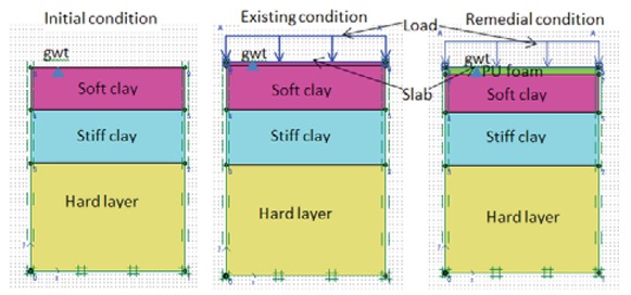
Stages of construction; initial, existing and remedial condition.
2.1 Finite Element Method PLAXIS 2D
The basic equations of consolidation as used in PLAXIS [25] are based on Biot’s theory [26]. The formulations are based on small strain theory. Darcy’s law for fluid flow and elastic behaviour of soil skeleton are also assumed as in Eq. (1) and Eq. (2). The specific discharge, q is calculated based on the coefficient of permeability, k and the gradient of the ground water head. The head is defined as in Eq. (3).
where y is the vertical position, p is the stress in the pore fluid (negative for pressure) and γw is the unit weight of fluid. According to Terzaghi’s principles, total stresses are divided into effective stresses and pore pressures as in Eq. (4).
where:
σ = (σxx+ σyy+ σzz+ σxy+σyz+σzx)T and
m = (1 1 1 0 0 0)T
mis a vector containing unity for normal stress and 0 term for shear stress component. Steady state solution at the end of consolidation is denoted as psteady as in Eq. (5).
Pinput is the pore pressure generated during input data based on ground water flow calculation. The constitutive equation denoting effective stress and strain relationship is as in Eq. (6).
M = material stiffness matrix, σ and ϵ are the stress and strain increment respectively.
2.2 Material Properties
The physical and engineering properties of marine clay soil were obtained from laboratory tests that were carried out on a few samples of marine clay soil taken from Selangor area as tabulated in Table 1. Standard test method BS 1377:1990 was referred. The effective shear strength parameters for different types of soil were obtained from Consolidated Undrained tests whilst the compressibility parameters of soft clay were obtained from Oedometer test. The properties of PU foam have been adopted from a previous study [27] as shown in Table 1. The slab in this model is used to spread the applied load evenly to the underlying soil. The properties of slab with the thickness of 75 mm are shown in Table 2. The minimum thickness of slab was adopted in order to distribute the overburden load evenly to the underlying soil. The analyses were carried out on different thickness of PU foam which are 0.25 m, 0.5 m, 1m, 1.5m and 2m, respectively. The PU foam thickness was adopted as to facilitate the excavation and replacement at shallow depth of soil. The limitation of PU thickness is up to 2 m considering the difficulties and stability of excavation works on soft soil. The overburden load imposed on the existing and improved soil was analysed ranging from 0 kPa, 5 kPa, 10 kPa and 15 kPa, respectively. The load was chosen as the focus of this study was to facilitate the adequate overburden load in order to resist excessive uplift with maximum PU foam thickness of 2 m. As the load larger, the uplift effect is not significant. The slab with the weight of 1.8 kN/m/m was also considered as an additional load imposed on the existing and improved soil.
Properties of soil and PU
| Soft clay | Stiff clay | Hard layer | PU | ||
|---|---|---|---|---|---|
| Type | Undrained | Drained | Drained | Nonporous | |
| Model | Soft Soil Creep | Mohr Coulomb | Mohr Coulomb | Linear Elastic | |
| γunsat | [kN/m3] | 14 | 16 | 18 | 3 |
| γsat | [kN/m3] | 15 | 18 | 20 | - |
| kx | [m/day] | 1.45E10−4 | 0.001 | 0.010 | - |
| ky | [m/day] | 1.45E10−4 | 0.001 | 0.010 | - |
| Eref | [kN/m2] | - | 25000 | 50000 | 30000 |
| ν | [-] | 0.5 | 0.3 | 0.3 | 0.3 |
| cref | [kN/m2] | 3 | 4 | 5 | - |
| φ | [◦] | 22 | 28 | 30 | - |
| λ* | 0.093 | ||||
| κ* | 0.041 | ||||
| μ* | 0.0046 |
Properties of slab.
| Identification | EA | EI | w | v | Mp | Np |
|---|---|---|---|---|---|---|
| [kN/m] | [kNm2/m] | [kN/m/m] | [-] | [kNm/m] | [kN/m] | |
| Slab | 3.75E6 | 1758 | 1.8 | 0.20 | 0 | 1E15 |
There are 3 stages of construction considered in the analysis namely initial, existing and remedial conditions as shown in Fig. 1. For both existing and remedial condition, the duration for consolidation analysis was carried out for 1 year each in order to determine the behaviour of both conditions in term of settlement and uplift in undrained condition. The undrained condition was considered for soft clay soil to monitor the excessive pore water pressure behaviour when being loaded with overburden. The initial condition represented the condition of site before any construction was carried out. The second stage represented the condition of site after construction of structure completed and accommodated. At this stage, excessive settlement occurred due to poor condition of soil foundation which affects the stability of existing infrastructure. Therefore, immediate remedial work is required to avoid further deterioration of the structural stability due to excessive and differential settlement. To model the remedial works condition, the third stage is adopted. For remedial works, the soft soil at shallow depth is excavated and removed, then replaced with PU foam slab.
3 Results and Discussions
3.1 Effect of pore water pressure (pwp)
Active pore water pressure (pwp), Ua is the total of hydrostatic pwp, Uh and excess pwp, Ue. Fig. 2 and Fig. 3 show pwp diagram from PLAXIS output for displacement, active and excess pwp for 1 m thickness of PU with 2 different overburden conditions those are overburden from slab only and 5 kPa overburden load and slab whilst Table 3 is the tabulation of results for 1 m thickness of PU with variation in overburden pressures as an example.
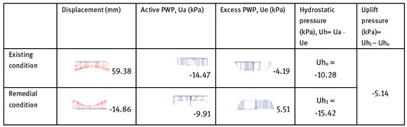
PLAXIS results for displacement, active and excess PWP for 1 m thickness of PU with load from slab only.
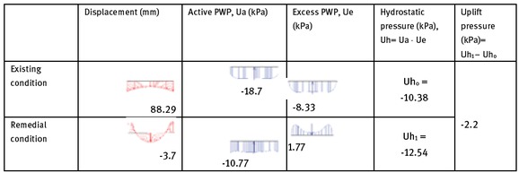
PLAXIS results for displacement, active and excess PWP for 1 m thickness of PU with load of 5 kPa and slab.
Results for displacement, active and excess pwp for 1 m thickness of PU with variation in loads.
| Load (kPa) | Existing condition | Remedial condition | |||||||
|---|---|---|---|---|---|---|---|---|---|
| Displacement | Active PWP | Excess PWP | Hydrostatic PWP | Displacement | Active PWP | Excess PWP | Hydrostatic PWP | Uplift force | |
| (mm) | (kPa) | (kPa) | (kPa) | (kPa) | (mm) | (kPa) | (kPa) | (kpa) | |
| 0 | 58.9 | -13.9 | -2.8 | -10.9 | -21.9 | -10.9 | 7.2 | -17.4 | -7.12 |
| Slab Slab | 59.4 | -14.5 | -4.19 | -10.3 | -14.9 | -9.91 | 5.5 | -15.4 | -5.14 |
| and | 88.3 | -18.7 | -8.33 | -10.4 | -3.67 | -10.8 | 1.8 | -12.5 | -2.2 |
| 5 kPa | |||||||||
| Slab | |||||||||
| and | 118 | -21.2 | -11.4 | -9.8 | 11.6 | -15.1 | -4.3 | -10.8 | 1.03 |
| 10 kPa | |||||||||
For existing condition, an increase in overburden loads cause increase in excess pwp. The excess pwp will be dissipated out over the time and return to hydrostatic pwp. Whereas for remedial condition, lesser overburden causes an excess pwp to act upward direction and turn to downward direction (-ve signed) with the increase in overburden loads. On the other hand, the hydrostatic pwp for existing and remedial condition is the differences between active and excess pwp measured underneath PU foam. As the PU foam is constructed to replace the soft soil, the pwp being pushed downward and accumulated underneath the non-porous PU foam as the density of PU is lesser than water provided the condition is undrained. Due to the upward displacement of excess pwp, the hydrostatic pwp underneath PU increases. For both existing and remedial condition, the excess pwp eventually will return to hydrostatic pwp, however, there are differences between both conditions whereby for existing condition, the excess pwp will return to hydrostatic pwp after water has dissipated out over the time and caused downward displacement (settlement), whereas for a remedial condition with PU, lesser overburden causes excess pwp to act upward that cause upward displacement and the pwp will return to existing hydrostatic pwp when the overburden load is adequate to resist uplift. Uplift pressure may be defined as the pressure exerted in upward direction by the groundwater underneath structure (slab/pavement). It is the differences in hydrostatic pressure between existing and remedial conditions. The excess of hydrostatic pwp during remedial works that accumulated underneath PU cause uplift pressure whereby the PU foam being pushed up by the increment of hydrostatic pwp. This scenario is elaborated as a graphical plot as shown in Fig. 4 indicating the increase in hydrostatic pressure for remedial condition in comparison to hydrostatic pressure for existing condition results in the increase of uplift pressure.
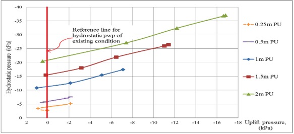
Linear relationship between hydrostatic pwp and uplift pressure.
Based on Fig. 4, at 0 uplift pressures, the hydrostatic pwp for existing condition (Uho) is represented. As no uplift pressure is occurred, the hydrostatic pwp of remedial condition similar to hydrostatic pwp of existing condition. At this moment, the overburden load is adequate to resist uplift. The linear relationship between hydrostatic pwp of existing, remedial conditions and uplift pressure as Eq. (7) is adopted from the graph in Fig. 4. From the equation, the differences in hydrostatic pwp between existing condition (Uho) and PU remedial condition (Uh1) cause uplift and upward displacement.
Fup = Uplift pressure (kPa)
Uho = Hydrostatic pressure of existing condition (kPa)
Uh1 = Hydrostatic pressure of PU remedial works (kPa)
Fig. 5 shows the effect of hydrostatic pwp to the occurrence of uplift and settlement with variation in PU foam thickness. For existing condition, the settlement increases with the increase of overburden load. The difference in hydrostatic pwp for existing condition is due to the indication of hydrostatic pressure at the depth of PU foam thickness as a comparison purpose between existing and remedial condition. Hydrostatic pwp for existing condition is constant with the increase of overburden load whereas for remedial conditions, the hydrostatic pwp decreases with the increase of overburden loads.
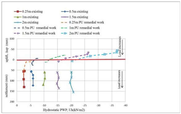
The effect of hydrostatic pore water pressure to the upward displacement (uplift) and settlement of existing and remedial works condition.
For existing condition, the hydrostatic pressure remain whilst excess pore pressure increase with the increase of overburden and return to hydrostatic pressure after dissipation of water. Whereas for remedial condition, the load reduces as the soft soil is replaced by PU foam, thus the hydrostatic pressure able to go upward that results in the increase in hydrostatic pressure. However, due to the lesser density of PU compared to water, the increase in hydrostatic pressure cause uplift pressure as the water is pushed to be underneath the PU foam as the foam was constructed underneath infrastructure. In order to reduce uplift pressure, more overburden load is required. The excess pwp due to overburden load was ceased when the load is sufficient to resist uplift, thus the pwp return to hydrostatic condition as indicated by horizontal line of graph in Figs. 5 and 6.
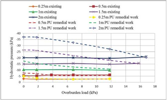
Hydrostatic pore water pressure and overburden load relationship with variation of PU foam thickness
3.2 Settlement and uplift behaviour
From finite element analysis, the existing condition experiences significant consolidation settlement ranging from 60 mm to 150 mm for 1-year duration and increases with the increase of overburden pressure as shown in Fig. 7. Immediate rectification work is required to prevent further excessive settlement and differential settlement that will jeopardise the stability of existing structure. Remedial works with PU has successfully reduced settlement significantly as shown in Fig. 7. However, the thickness of PU foam and overburden pressure are the important aspects to be considered as it affects the pattern of settlement and uplift. The soft clay in this study is in undrained condition and has low permeability, hence it takes long time to dissipate out the water. The buoyancy of PU foam will produce uplift pressure that causes upward displacement of the soil. The minimum overburden pressure to resist uplift pressure with variation of PU foam thickness was determined in this study. Excessive uplift pressure results in the differential settlement and excessive movement of structure hence lead to instability of structure such as structural crack and collapse.
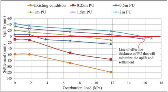
Design chart of settlement and upward displacement (uplift) with variation of PU thickness and overburden load.
From Figure 7, existing condition shows settlement increase with the increase of overburden pressure. The overburden load is considered as the load from infrastructure. At zero overburden load, the load from soil above the location of settlement being measured cause settlement as shown in Fig. 7. For remedial works condition with PU thickness of 0.25 m, the settlement obviously decreases compared to existing condition. With remedial works of 0.5mPU thickness, uplift occurred when overburden pressure is less than 2.5 kPa, nonetheless, beyond 2.5 kPa until 12 kPa of overburden pressure, the settlement is within the tolerable value. 1 m thickness of PU introduced uplift whenever overburden pressure less than 8 kPa, and the maximum pressure of 14 kPa is required to ensure the tolerable settlement value is achieved. For 1 m and 2 m thickness of PU, larger overburden pressure is required to resist the uplift of the foam. Thus, as the thickness of PU foam increases, the minimum overburden load to resist uplift increases as shown in Fig. 8. The displacement diagram from finite element analysis indicating upward and downward displacement of soil with variation of PU thickness and overburden loads of 0, 5 kPa and 10 kPa for existing and remedial works conditions are shown in Fig. 9. It can be concluded from the diagram, with the increase in thickness of PU foam, higher overburden load is required to resist uplift.
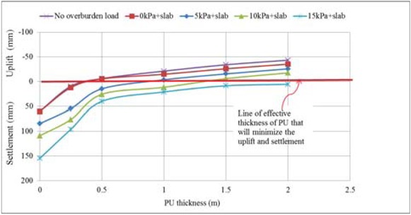
Design chart of settlement and upward displacement (uplift) with variation of overburden and PU foam thickness
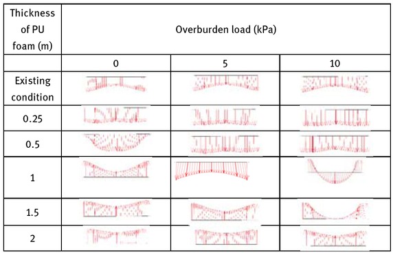
Upward and downward displacement of soil with variation in PU foam thickness and overburden load of 0, 5 kPa and 10 kpa for existing and remedial conditions
On top of that, PU foam design chart is produced as shown in Fig. 8 indicating the exponential relationship of settlement and uplift with variation of PU foam thickness and overburden pressure. The effective thickness of PU foam can be determined from this chart by considering the tolerable settlement required in the design. However, beyond the effective thickness of PU foam, the increase in PU foam thickness results in the increase of uplift pressure, therefore, minimum overburden is adopted to resist uplift. The occurrence of uplift is due to the downward pressure imposed to the subsoil lesser than the up ward pressure from pore water. The thickness of PU foam is an important consideration as the increase in PU thickness being pushed down within the saturated soil causes the increase in the volume of water to be displaced by PU foam. The weight of displaced water is equal to the buoyant force whereby the Archimedes’ principle is valid. The increase in weight of displaced water results in the increase in buoyant force. Thus, downward pressure from overburden is increased to counter the increase in buoyant force that is acting upward.
Comparison of uplift pressure from finite element method analysis is in a good agreement with analytical method. The analytical method was carried out by manual calculation of upward and downward pressure based on Archimedes’ principle on buoyancy as represented by Figs. 10 and 11. A slight difference at certain analysis point probably due to the effect of soil skeleton exists in saturated soil whereas the analytical method is considering water saturated condition. For analytical method, the uplift pressure is measured by considering the differences between upward and downward pressure acting on the stabilised soil. The downward pressure exerted by the load from overburden and slab whilst the upward pressure exerted by pore pressure accumulated underneath the PU foam which is equal to the weight of displaced water by the PU foam, ρwgV or simplified to γwh per metre square area. According to Archimedes’ principle, the weight of displaced water is equal to the upward buoyant force. If the upward buoyant force exceeds the total downward force, the soil will experience uplift.
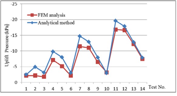
Verification of finite element analysis results on uplift pressure
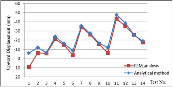
Verification of finite element analysis results on upward displacement
Archimedes’ principle is valid with the findings of this study whereby it indicates that the upward buoyant force that is exerted on a body immersed in a fluid, whether fully or partially submerged, is equal to the weight of the fluid that the body displaces and it acts in the upward direction at the centre of mass of the displaced fluid. Archimedes’ principle is a law of physics fundamental to fluid mechanics formulated by Archimedes of Syracuse [28].
4 Conclusions
The settlement of soil reduces significantly with PU foam mitigation method as the PU foam is a lightweight material. However, buoyancy of lightweight materials is a major concern to cause uplift pressure that affects the stability of structure. The minimum overburden pressure required to resist the uplift pressure increases with the increase of PU foam thickness. From finite element method, uplift pressure is measured by assessing the differences in hydrostatic pressure for existing condition and remedial condition as the pore water pressure after remedial work is increased underneath PU foam.
For existing condition, the increase of overburden load cause the increase in excess pore pressure and over the time it returns to hydrostatic pressure. Whereas for remedial condition, the load reduces as the soft soil is replaced by PU foam, thus the hydrostatic pressure able to go upward that results in the increase in hydrostatic pressure. However, as the density of PU as non-porous material is lesser than density of water, the existing water level is pushed to be underneath the PU foam. Therefore, the increase in hydrostatic pressure causes uplift pressure. The results of finite element analysis exhibited the same trend with analytical method carried out for the same model. The chart of effective PU foam thickness produced in this study would be able to assist practising engineer to adopt the effective thickness of PU foam in order to minimise the settlement into tolerable value and simultaneously resist uplift. Subsequently, the use of effective thickness will be able to reduce the cost of remedial measures.
Nomenclatures
- γ
Unit weight
- k
Coefficient of permeability
- E
Young,’s Modulus
- c
Cohesion
- ρ
Density
Greek Symbols
- λ*
Slope of normal consolidation line
- κ*
Slope of over-consolidation (swelling) line)
- μ*
Slope of critical state line
- φ
Soil friction angle
Abbreviations
- PU
Polyurethane
- pwp
Pore water pressure
- v
Poisson’s ratio
- EA
Axial stiffness
- EI
Flexural rigidity
- w
Weight
- Mp
Maximum bending moment
- Np
Maximum axial force
Acknowledgement
Special thanks to UiTM research fund for the publication financial support.
References
[1] Badri K., Biobased Polyurethane from Palm Kernel Oil Based Polyol. Licensee InTech., 2012.Search in Google Scholar
[2] www.essentialchemicalindustry.org/polymers/polyurethane.html assessed on 20/8/2018.Search in Google Scholar
[3] Daigavane, P.B.; and Jain, K., Improved foundation system on Marine Clay using geofoam, International Journal of Modern Trends in Engineering and Research (IJMTER), Volume 02, Issue 02, 2015.Search in Google Scholar
[4] Stephen, S., Pressure Reduction on Wide Culverts with EPS Geofoam Backfill. Dissertations, Syracuse University - ALL. 548. http://surface.syr.edu/etd/548 2016.Search in Google Scholar
[5] Frydelund, T.E.; and Aaboer, R., Lighweight filling materials for road construction, EPS Geofoam 3rd International Conference, Salt Lake City, 2002Search in Google Scholar
[6] Riad, H.L., Ricci, A.L., Osborn, P.W., D’Angelo, D.A., and Horvath, J.S., Design of lightweight fills for road embankments on Boston’s Central Artery/Tunnel Project. International Conference on Case Histories in Geotechnical Engineering. http://scholarsmine.mst.edu/icchge/5icchge/session08/5,2004Search in Google Scholar
[7] Frydelund, T.E.; and Aaboer, R., Use of waste materials as for lightweight fills, International Workshop on Lightweight Geomaterial. Tokyo, Japan. 2002.Search in Google Scholar
[8] Han J. and Gabr M.A., Numerical analysis of geosyntheticreinforced and pile-supported earth platforms over soft soil, J. Geotech. Geoenviron. Eng., Vol. 128 (1): 44-53, 2002.10.1061/(ASCE)1090-0241(2002)128:1(44)Search in Google Scholar
[9] Ariyarathne P., Liyanapathirana D.S. and Leo C.J., Comparison of different two-dimensional idealizations for a geosyntheticreinforced pile-supported embankment. Int. J. Geomech., Vol. 13 (6): 754-768, 2013.10.1061/(ASCE)GM.1943-5622.0000266Search in Google Scholar
[10] Stuedlein A.W. and Negussey D., Use of EPS Geofoam for support of a bridge. Sound Geotechnical Reasearch to Practice: honoring RobertD.Holtz, Geotechnical Speacial Publication No. 230, ASCE, Reston, VA., pp. 344-345, 2013, http://ascelibrary.org/doi/pdfplus/10.1061/9780784412770.02210.1061/9780784412770.022Search in Google Scholar
[11] Ghani A.N.A, Radzi S. M., Ismail M.S.N, Hamid A.H.A., A study on the use of polyurethane for road flood damage control, International Journal of GEOMATE. 12(32):82-87. April 2017. DOI: 10.21660/2017.32.661610.21660/2017.32.6616Search in Google Scholar
[12] Mohamed Jais, I. B. (2017). Rapid remediation using polyurethane foam / resin grout in Malaysia. Geotechnical Reseach, 4(GR2), 107–117. https://doi.org/10.1680/jgere.17.00003 Paper10.1680/jgere.17.00003Search in Google Scholar
[13] http://www.technifoam.com/foam-materials/expandedpolystyrene-eps/ assessed on 15/1/2018Search in Google Scholar
[14] Howard G.T., Polyurethane Biodegradation. Environmental Science and Engineering, DOI: 10.1007/978-3-642-23789-8_14. Springer-Verlag Berlin Heidelberg, 2012.10.1007/978-3-642-23789-8_14Search in Google Scholar
[15] Singh D., Chen N., Martin C.L, and Routbort J.L., Pagilla and Demirtas M.U., Reddy K. and Gangathulasi J., Del Cul G.D., Simmons C.M., and Icenhour A.S., Study on Degradation of a Commercial Rigid Polyurethane Foam Used for Filling of Process Gas Equipment (PGE) and Pipes and Corrosion Behavior of Pipes at K-25/K-27. Argonne National laboratory, Nuclear Engineering Division, 2006.10.2172/895663Search in Google Scholar
[16] Huntsman. A Guide to Thermoplastic Polyurethanes (TPU), www.huntsman.com assessed on 1/1/2017Search in Google Scholar
[17] Kaplan A.M. and Darby R.T., Fungal susceptibility of polyurethanes, Appl Microbiol 16:900–905, 1968.10.1128/am.16.6.900-905.1968Search in Google Scholar PubMed PubMed Central
[18] Kaplan A.M., Darby R.T., Greenberger M. and Rodgers M.R., Microbial deterioration of polyurethane systems, Dev Ind Microbiol 82:362–371, 1968.Search in Google Scholar
[19] http://www.iowacoolers.com/structural_insulated_panels/poly_eps_insulation.html Assessed on 15/1/2018Search in Google Scholar
[20] Biot, M.A., General theory of three-dimensional consolidation, Journal of Applied Physics, 12, 155–164, 1941.10.1063/1.1712886Search in Google Scholar
[21] Bowles, J.E., Foundation Analysis and Design, New York: McGraw-Hill, 2010.Search in Google Scholar
[22] Borges, J.L., Three-dimensional analysis of embankments on soft soils incorporating vertical drains by finite element method, Computers and Geotechnics, 31 (8), 665–676, 2004.10.1016/j.compgeo.2004.11.001Search in Google Scholar
[23] Tavenas, F., Some aspects of clay behaviour and their consequences on modeling techniques. American Society for Testing and Materials, Special Technical Publication 1981, No. 740, pp. 667-677, 1981.10.1520/STP28781SSearch in Google Scholar
[24] Qian, J.H.; and Yin, Z.Z., Geotechnical principles and calculation. Chinese Water Conservancy Hydroelectric lems, The Engineer, 1996.Search in Google Scholar
[25] Brinkgreve, R.B.J., Plaxis 2D Version 8, Material Models Manual. Delft University of Technology & PLAXIS b.v., The Netherlands, 2002.Search in Google Scholar
[26] Biot, M.A., General solutions of the equations of elasticity and consolidation for porous material. Journal of Applied Mechanics, 23, 2, 1956.10.1115/1.4011213Search in Google Scholar
[27] Lat, D.C.; Jais, I.B.M.; Mohamed, K.T.; and Razali, R., Performance comparison between polyurethane injection pile and slab system against lighweight concrete as a ground improvement using finite element analysis, Journal of Applied Science Research, ISSN 1819-544x, 2015 special,11(20), pages 11-16, 2015.Search in Google Scholar
[28] Heath, T.L., The works of Archimedes, Edited in Modern Notation with Introductory Chapters, United Kingdom: Cambridge University, 1897.Search in Google Scholar
© 2019 D.C. Lat et al., published by De Gruyter
This work is licensed under the Creative Commons Attribution 4.0 International License.
Articles in the same Issue
- Regular Article
- Exploring conditions and usefulness of UAVs in the BRAIN Massive Inspections Protocol
- A hybrid approach for solving multi-mode resource-constrained project scheduling problem in construction
- Identification of geodetic risk factors occurring at the construction project preparation stage
- Multicriteria comparative analysis of pillars strengthening of the historic building
- Methods of habitat reports’ evaluation
- Effect of material and technological factors on the properties of cement-lime mortars and mortars with plasticizing admixture
- Management of Innovation Ecosystems Based on Six Sigma Business Scorecard
- On a Stochastic Regularization Technique for Ill-Conditioned Linear Systems
- Dynamic safety system for collaboration of operators and industrial robots
- Assessment of Decentralized Electricity Production from Hybrid Renewable Energy Sources for Sustainable Energy Development in Nigeria
- Seasonal evaluation of surface water quality at the Tamanduá stream watershed (Aparecida de Goiânia, Goiás, Brazil) using the Water Quality Index
- EFQM model implementation in a Portuguese Higher Education Institution
- Assessment of direct and indirect effects of building developments on the environment
- Accelerated Aging of WPCs Based on Polypropylene and Plywood Production Residues
- Analysis of the Cost of a Building’s Life Cycle in a Probabilistic Approach
- Implementation of Web Services for Data Integration to Improve Performance in The Processing Loan Approval
- Rehabilitation of buildings as an alternative to sustainability in Brazilian constructions
- Synthesis Conditions for LPV Controller with Input Covariance Constraints
- Procurement management in construction: study of Czech municipalities
- Contractor’s bid pricing strategy: a model with correlation among competitors’ prices
- Control of construction projects using the Earned Value Method - case study
- Model supporting decisions on renovation and modernization of public utility buildings
- Cements with calcareous fly ash as component of low clinker eco-self compacting concrete
- Failure Analysis of Super Hard End Mill HSS-Co
- Simulation model for resource-constrained construction project
- Getting efficient choices in buildings by using Genetic Algorithms: Assessment & validation
- Analysis of renewable energy use in single-family housing
- Modeling of the harmonization method for executing a multi-unit construction project
- Effect of foam glass granules fillers modification of lime-sand products on their microstructure
- Volume Optimization of Solid Waste Landfill Using Voronoi Diagram Geometry
- Analysis of occupational accidents in the construction industry with regards to selected time parameters
- Bill of quantities and quantity survey of construction works of renovated buildings - case study
- Cooperation of the PTFE sealing ring with the steel ball of the valve subjected to durability test
- Analytical model assessing the effect of increased traffic flow intensities on the road administration, maintenance and lifetime
- Quartz bentonite sandmix in sand-lime products
- The Issue of a Transport Mode Choice from the Perspective of Enterprise Logistics
- Analysis of workplace injuries in Slovakian state forestry enterprises
- Research into Customer Preferences of Potential Buyers of Simple Wood-based Houses for the Purpose of Using the Target Costing
- Proposal of the Inventory Management Automatic Identification System in the Manufacturing Enterprise Applying the Multi-criteria Analysis Methods
- Hyperboloid offset surface in the architecture and construction industry
- Analysis of the preparatory phase of a construction investment in the area covered by revitalization
- The selection of sealing technologies of the subsoil and hydrotechnical structures and quality assurance
- Impact of high temperature drying process on beech wood containing tension wood
- Prediction of Strength of Remixed Concrete by Application of Orthogonal Decomposition, Neural Analysis and Regression Analysis
- Modelling a production process using a Sankey diagram and Computerized Relative Allocation of Facilities Technique (CRAFT)
- The feasibility of using a low-cost depth camera for 3D scanning in mass customization
- Urban Water Infrastructure Asset Management Plan: Case Study
- Evaluation the effect of lime on the plastic and hardened properties of cement mortar and quantified using Vipulanandan model
- Uplift and Settlement Prediction Model of Marine Clay Soil e Integrated with Polyurethane Foam
- IoT Applications in Wind Energy Conversion Systems
- A new method for graph stream summarization based on both the structure and concepts
- “Zhores” — Petaflops supercomputer for data-driven modeling, machine learning and artificial intelligence installed in Skolkovo Institute of Science and Technology
- Economic Disposal Quantity of Leftovers kept in storage: a Monte Carlo simulation method
- Computer technology of the thermal stress state and fatigue life analysis of turbine engine exhaust support frames
- Statistical model used to assessment the sulphate resistance of mortars with fly ashes
- Application of organization goal-oriented requirement engineering (OGORE) methods in erp-based company business processes
- Influence of Sand Size on Mechanical Properties of Fiber Reinforced Polymer Concrete
- Architecture For Automation System Metrics Collection, Visualization and Data Engineering – HAMK Sheet Metal Center Building Automation Case Study
- Optimization of shape memory alloy braces for concentrically braced steel braced frames
- Topical Issue Modern Manufacturing Technologies
- Feasibility Study of Microneedle Fabrication from a thin Nitinol Wire Using a CW Single-Mode Fiber Laser
- Topical Issue: Progress in area of the flow machines and devices
- Analysis of the influence of a stator type modification on the performance of a pump with a hole impeller
- Investigations of drilled and multi-piped impellers cavitation performance
- The novel solution of ball valve with replaceable orifice. Numerical and field tests
- The flow deteriorations in course of the partial load operation of the middle specific speed Francis turbine
- Numerical analysis of temperature distribution in a brush seal with thermo-regulating bimetal elements
- A new solution of the semi-metallic gasket increasing tightness level
- Design and analysis of the flange-bolted joint with respect to required tightness and strength
- Special Issue: Actual trends in logistics and industrial engineering
- Intelligent programming of robotic flange production by means of CAM programming
- Static testing evaluation of pipe conveyor belt for different tensioning forces
- Design of clamping structure for material flow monitor of pipe conveyors
- Risk Minimisation in Integrated Supply Chains
- Use of simulation model for measurement of MilkRun system performance
- A simulation model for the need for intra-plant transport operation planning by AGV
- Operative production planning utilising quantitative forecasting and Monte Carlo simulations
- Monitoring bulk material pressure on bottom of storage using DEM
- Calibration of Transducers and of a Coil Compression Spring Constant on the Testing Equipment Simulating the Process of a Pallet Positioning in a Rack Cell
- Design of evaluation tool used to improve the production process
- Planning of Optimal Capacity for the Middle-Sized Storage Using a Mathematical Model
- Experimental assessment of the static stiffness of machine parts and structures by changing the magnitude of the hysteresis as a function of loading
- The evaluation of the production of the shaped part using the workshop programming method on the two-spindle multi-axis CTX alpha 500 lathe
- Numerical Modeling of p-v-T Rheological Equation Coefficients for Polypropylene with Variable Chalk Content
- Current options in the life cycle assessment of additive manufacturing products
- Ideal mathematical model of shock compression and shock expansion
- Use of simulation by modelling of conveyor belt contact forces