The novel solution of ball valve with replaceable orifice. Numerical and field tests
-
Grzegorz Romanik
 and
Janusz Rogula
and
Janusz Rogula

Abstract
The article presents the results of numerical calculations and experimental results of a flow through the orifice. Such a measuring device was built-into the ball valve that gave unique possibility of the orifice exchange without the pipeline disassemble. The advantages of using the prototypical solution has been described. This patented solution has been tested extensively for the durability and tightness. The article contains comparison between flow character in the case of single-hole orifice and a multi-nozzle one. The prototypical measuring device has been produced and assembled in compressed air system in the Power Plant Opole, that gave experimental verification of theoretical approach.
1 Introduction
Measurement of gas flow in power industry require various accuracy. Orifice method is the one of standardized [1], however its precision depends on pipe length in front of and behind the orifice, and a relation between the pipe diameter and orifice hole diameter. Small diameter of orifice hole generates high flow resistance. Here one can place the conflict between measurement accuracy and flow resistance. One of possibility of accuracy improvement is application of solution patented by ZPDA Ostrow Wielkopolski [2].
Another problems that exist in described construction are more additional places of leakage. It’s a consequence of more complicated construction, as the orifice is built into ball valve. Hence there are typical possible places of leakage like in typical ball valve. However the patented construction enables fast trouble-free and safe replacement of the orifice. Such solution allowed to carry-out measurement temporarily, that does not generate resistance in permanent way, since the orifice can be removed.
In order to localize the leakage ways and durability of described construction at different temperatures relevant tests have been carried-out [3].
Possibility of the orifice exchange enabled application of patented multi-nozzle orifice [4] that generates lower flow resistance. Multi-nozzle orifice characterize the same coefficient of contraction β.
Manufacturers of fluid flow measuring devices in recent years have begun searching for solutions characterized by lower hydraulic losses and allowing for increased accuracy of measurement. For this purpose, consideration has been given to multi-nozzle orifices currently used by many research centers. Finding specific information about the results of research is very difficult. Figure 1 shows examples of the holes arrangement on the orifice disk. This type of research is extremely important in an era of times where savings are sought everywhere. In large plants, such as, power plants, consumption reduction by several tenths of a percent per year may turn out to be a significant saving.
![Figure 1 Example of multi-nozzle flanges a) 13-hole flange analyzed by Malavasi et al., B) 6-hole flange designed by Huang c) example of the flange analyzed by Zhao et al d) flange used by Emerson Rosemount in its gauges [5]](/document/doi/10.1515/eng-2019-0034/asset/graphic/j_eng-2019-0034_fig_001.jpg)
Example of multi-nozzle flanges a) 13-hole flange analyzed by Malavasi et al., B) 6-hole flange designed by Huang c) example of the flange analyzed by Zhao et al d) flange used by Emerson Rosemount in its gauges [5]
Numerical calculation using the Navier-Stokes equation were performed in case of various configuration of holes position (Figure 1) and described in [5]. Then the flanges for the DN 100 diameter according with Figure 2 were produced and subjected it to field tests.
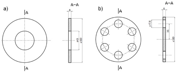
Measuring orifice a) standardized one-hole flange b) multi-hole flange developed by ZPDA from Ostrow Wielkopolski
The orifices shown in Figure 2 have the same coefficient of contraction β.
Assembly of the prototype valve in the compressed air system in the Opole Power Plant gave possibility of verification of the numerical calculations results with the experiment.
2 Object of research
Figure 3a presents a ball valve prototype with a replaceable measuring orifice (diameter DN100), and a cross section of the valve in Figure 3b.
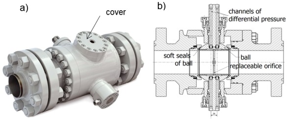
Valve prototype with measuring orifice a) view, b) section with a description of the main elements
The prototype was built into ball valve with the so-called a trunnion-mounted ball. The solution is that the ball in the valve is supported by two pins gripped in the bearing bushes. The pins are used to rotate the ball. The replaceable orifice, mounted inside the ball hole, acts as an element of the measurement system only during full opening of the passage. The accumulation of the medium in front of the orifice creates a pressure difference in front of and behind it. In order to measure the differential pressure, in the pins holes are drilled in such a way that one hole is in front of and the other behind the orifice. Figure 4 shows the prototype of the valve with impulse channels connected to the spindle and differential pressure transducer.
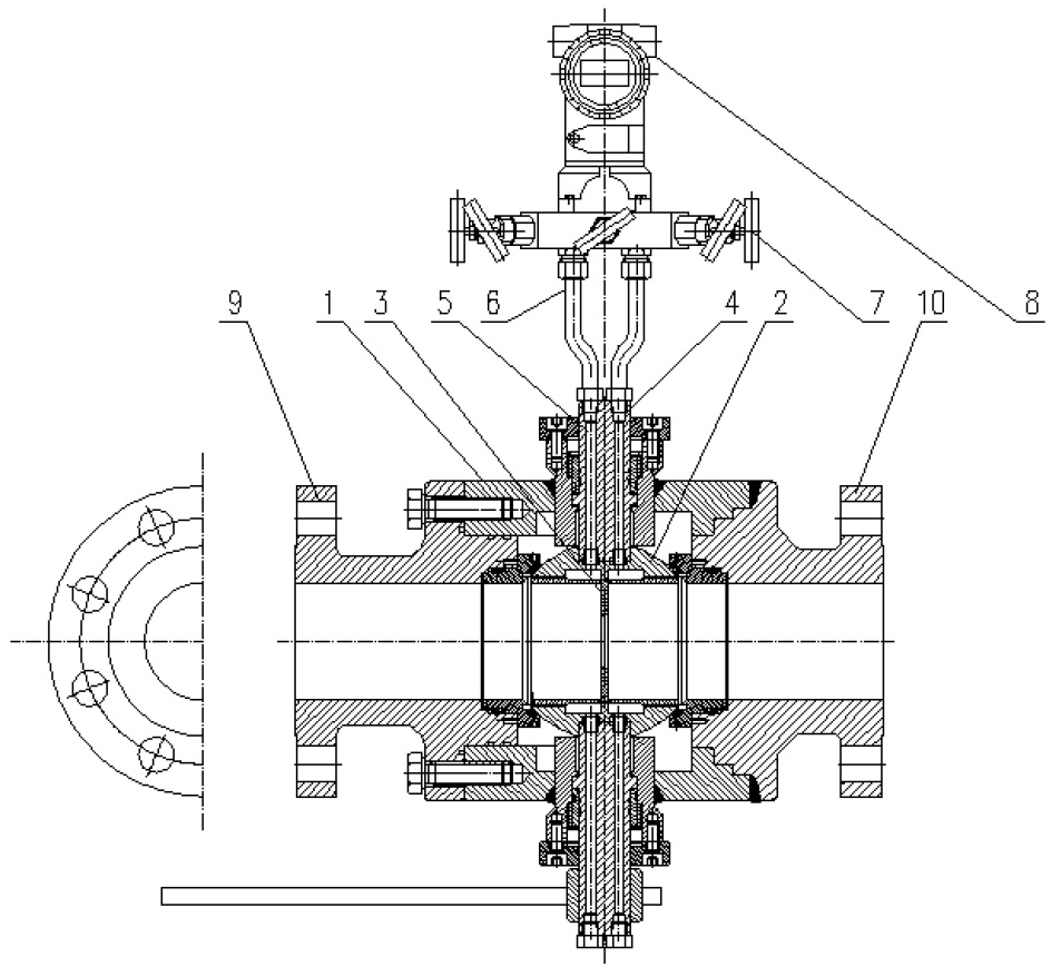
The cross-section of the prototype, 1 - Valve body, 2 - Ball, 3 - Measuring orifice, 4 - Spindle, 5 – Pressure impulse channel, 6 - Impulse tube, 7 - Five-way valve, 8 - Differential pressure transducer, 9 - Inlet connection flange, 10 - Outlet connection flange
The valve body is made of P355NH steel, pin - X6CrNiTi 18-10 steel, ball X20Cr13, orifice - austenitic steel 1.4541 - Figure 5.
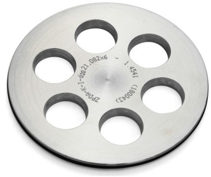
Multi-nozzle flange
This selection of construction materials allows measurements also in environment of the natural gas or oil. Removal of the cover (Figure 3a) allows the replacement of the orifice with a different coefficient of contraction β or the use of a multi-nozzle orifice without the need to dismantle the entire device and the long-term interruption in medium transfer.
Preliminary research [6] on the multi-nozzle flange indicates that the advantage of using it is that the flow losses through the orifice made according to the patented invention are significantly smaller than in the case of a cylinder-shaped orifice. In addition, when the liquid is flowing, the nozzles made according to the invention are more resistant to the formation of cavitation, which allows measurements at higher flow rates. The research on the prototype is carried out under the Operational Program - Intelligent Development (POIR 01.01.01-00-0013 / 15 “Development of a device for measuring the flow of utilities on industrial mains”).
3 Preliminary research
Before mounting the prototype of the valve in the compressed air system in the Opole Power Plant, the internal and external leak testing of the valve prototype DN100 was carried out. Then, for a prototype with a single-hole measuring orifice, calculations were made according to the standard using a dedicated application. The normative calculations made for a single-hole flange were compared with the results obtained using the CFD ANSYS calculation software. Calculations have been carried-out using resources provided by Wroclaw Centre for Networking and Supercomputing (http://wcss.pl) grant No.444. Numerical calculations of a multi-nozzle or single-hole flange with the same value of the coefficient of contraction β were carried out for the same initial conditions as were given by the power plant employees:
mass flow at the inlet: Q = 2000 Nm3/h,
air pressure at the inlet: p1 = 8 bar,
air temperature: T = 25∘C.
To carry out the calculations the following assumptions were made:
non-stationary simulation
turbulence model: k- epsilon,
grid model: unstructured.
The numerical mesh was constructed with elements of the tetra type in volume and of the prism in the boundary layer.
Parameters of mesh were the following:
nodes number: 2 113 315
elements number: 9 028 942
element quality (average): 0,828
aspect ratio (average): 0,18834
skewness (average): 0,2048
accuracy: 1 · 10−5
Boundary conditions – given flow, calculated pressure difference with assumed pressure of compressed air equal to 8 bar.
4 Numerical calculation of air flow through the prototype
Fluid mechanics is defined by the non-linearNavier-Stokes differential equations (1) defined by the principles of the momentum behavior and the fluid stream energy.
where:
(ϑ *∇)ϑ – transfer of momentum caused by the movement of liquids,
∇p – change of momentum caused by pressure force, ϑ∇2ϑ – friction forces
F – gravitation.
Knowledge of velocity fields, fluid pressures, temperature gradients, mass and heat flows is of great importance for effective and highly efficient design of devices.
Performing correct calculations using equation (1) using CFD (Computational Fluid Dynamics) software involves using packages for numerical calculations that have inbuilt programs that allow to go through the entire process of preparing a simulation from a geometry task to generating a grid and presenting the results. Basic blocks of CFD programs:
Preparation of geometry - implementation of the so-called “Water body”, then giving the “water body” finite volume and compaction of the mesh near the elements that may cause flow disturbances and the task of boundary conditions (preprocessing);
Calculation of the solution (solving);
Graphical presentation of results (postprocessing).
To prepare the geometry (determining the diameter of the tube, the diameter of the holes of the multi-hole flange and the diameter of the one-hole flange, the length of the tube sections through and behind the orifice) were used for measurements on the site and information obtained fromZPDA Ostrow Wielkopolski. Figure 6 shows a fragment of the prototypical valve installed on the installation of compressed air.
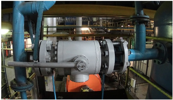
Fragment of the installation with the prototype valve with a measuring orifice
An orifice with a diameter of ø51 mm was assumed for calculations, while for a multi-nozzle six holes with a diameter of ø21 mm on the division diameter of ø60 mm were assumed.
Figure 7 shows the "water body" of the valve prototype with a measuring orifice.
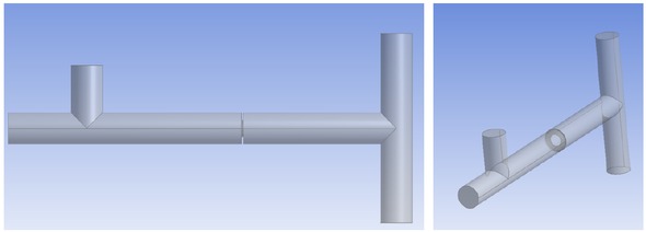
Three-dimensional model of the installation fragment with a measuring orifice
To increase the accuracy of the numerical calculation of the orifice set perpendicular to the air flow direction, the grid density at the inlet edges of the orifice holes has been increased (Figure 8), which allowed convergence of the simulation results.
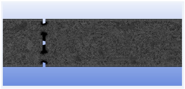
Increased density of nonstructural mesh with a boundary layer for a multi-nozzle orifice
Figure 9 presents the results of numerical speed calculations for a single-hole, and in Figure 10 for a multi-nozzle orifice.
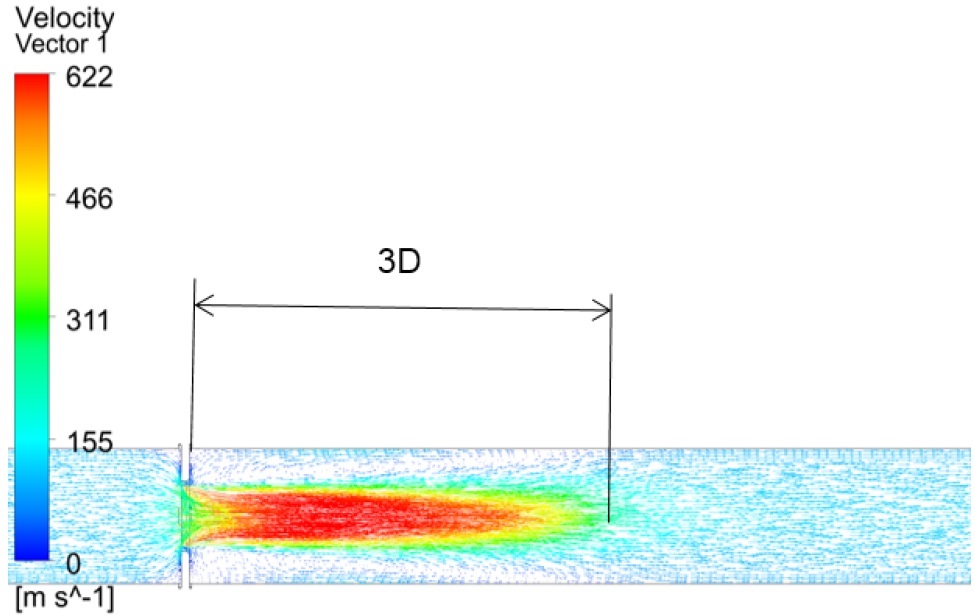
Velocity vectors for a single-hole orifice
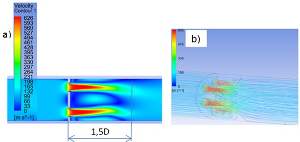
Velocity vectors for a multi-nozzle orifice, a) view in the plane of the cross-section, b) axonometric view
Analyzing the position of velocity vectors, it can be seen that the maximum velocity begins to stabilize after about 3 lengths of 3D diameter (Figure 9) for a single orifice and for a multi-hole 1.5D (Figure 10).
The illustration of the flow through the orifices of the valve obtained on the basis of solved equations of fluid mechanics allows to analyze the values of pressure gradients and velocities. Apart from the flow axis for a single-hole flange, one can notice a change in the direction and sense of velocity vectors, which may indicate the occurrence of turbulence. Analyzing the direction and sense of velocity vectors in the case of the multi-nozzle flange, it can be seen that it changes to the opposite one in the central part of the flow. In these places the phenomenon of returning flow may occur. In the case of a multi-hole orifice, there will be more vortex sites. It results from them (Figure 10) that the main streams can be deflected in the direction of the symmetry axis of the pipeline.
Bores ø 2 mm in the nut holding the orifice are used for measurement of the differential pressure. Pressure on the orifice hole edge was numerically calculated (Δp1). In order to measure the pressure in the bores of the nut necessary is the to calculate the pressure on the edge closer to the orifice flange (Δp2) and in the opposite side of the same bore (Δp3).
Pressure measurements resulting from narrowing are shown in Table 1.
Calculated air pressure difference for single-hole and multi-nozzle flanges
| Single-hole flange | Multi-nozzle flange | |
|---|---|---|
| Δp1 | 8,2 kPa | 10,8 kPa |
| Δp2 | 13,8 kPa | 17,2 kPa |
| Δp3 | 9,9 kPa | 13,2 kPa |
| Mean pressure in the | 11,8 kPa | 15,2 kPa |
| differential pressure | ||
| measurement channel | ||
| (Δp2+ Δp3)/2 |
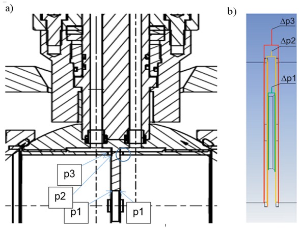
Pressure measurement points and differential pressure, p1 (Δp1) - measurement on the edge of the orifice hole, p2 (Δp2) - measurement on the edge of the hole closer to the front face of the orifice, p3 (Δp3) - measurement on the edge of the orifice hole located further on the orifice plane, a) view of pressure measurement points in the valve cross-section, b) view of the measurement locations on the sketch of the calculation program
5 Field tests of the prototype
The valve with a single-hole flange was assembled. In order to collect flow data it was decided to use a normative orifice. In further tests, the installation of a multi-nozzle flange is planned, but it must take place during the planned shutdown, during which every service action must be planned.
Table 2 presents the results obtained during the stay at the power plant.
Table of recorded results
| Lp. | qvn | qm | qv | p | Tp | ϱp | Δp |
|---|---|---|---|---|---|---|---|
| - | kPa | ∘C | kPa | ||||
| 1 | 295,5 | 398,8 | 41,0 | 790,7 | 29,4 | 9,1 | 0,5 |
| 2 | 298,4 | 402,7 | 41,4 | 790,6 | 29,4 | 9,1 | 0,5 |
| 3 | 293,2 | 395,7 | 40,7 | 790,7 | 29,4 | 9,1 | 0,5 |
| 4 | 295,8 | 399,2 | 41,0 | 790,7 | 29,3 | 9,1 | 0,5 |
| 5 | 294,5 | 397,5 | 40,9 | 790,5 | 29,4 | 9,1 | 0,5 |
| 6 | 294,3 | 397,2 | 40,8 | 790,6 | 29,4 | 9,1 | 0,5 |
| 7 | 295,1 | 398,3 | 40,9 | 790,7 | 29,4 | 9,1 | 0,5 |
| 8 | 296,1 | 399,6 | 41,1 | 790,6 | 29,3 | 9,1 | 0,5 |
| 9 | 294,9 | 398,0 | 40,9 | 790,8 | 29,4 | 9,1 | 0,5 |
| 10 | 295,2 | 398,4 | 41,0 | 790,7 | 29,4 | 9,1 | 0,5 |
The average of the results of the air volume flow measurements is 295,3 Nm3/h and this value differs fromthe assumptions,where the maximum value of 2000 Nm3/h was assumed. Therefore, for the prototype with a single-hole flange mounted, additional numerical calculations were
carried out, assuming the results of the flow rate obtained on the prototype in the field trial as the value of the input data for numerical calculations.
Figure 12 presents the results of numerical tests of a system with a single-hole measuring orifice using the same mesh density and type of turbulence as in calculations for maximum values.
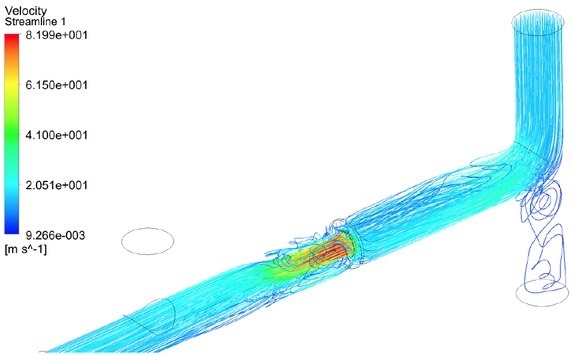
The results of numerical simulation in the form of a velocity line
6 Discussion
Geometry of the channels and orifice used in numerical simulation was constructed basing on delivered documentation. Length of the channels were implemented with respect to measurements of existed installation.
When comparing the pressure difference for a single-hole flange, determined by means of the numerical method, which is 11,8 kPa, with analytically obtained according to the Standard [1] – 11,465 kPa, one can notice a large convergence of results allowing to accept numerical calculations as correct. The difference, which is 0,335 kPa, may be due to the fact that the flange roughness is not included in the numerical method.
The numerical tests show us the real nature of the flow. It can be seen that the inlet bend disturbs the flow in front of the orifice and may cause false results. Minimal losses result in inactive branches of the pipeline because they cause vortices and recirculation. At the same time, the value of the pressure difference was read, which is Δp = 0,469 kPa. The difference with the results read from the measuring devices differs slightly (rounded value Δp = 0,5 kPa). The accuracy can be regarded as sufficient. Good simulation and experimental results caused the desire to obtain better results by using, for example, multi-hole flanges. In order to verify the validity of the idea of using a multi-hole flange, it was decided to conduct simulation tests for a 6-hole orifice. In order to be able to compare, numerical assumptions were assumed as for a single-hole flange. A clear shortening of the section with disturbed flow behind the barrier in the form of an orifice was observed when using the multi-hole model. The length of the section has been reduced by half. Comparing the values presented in Table 1, it can be concluded that the pressure drop across the multi-hole flange is greater at the same flow rate, which results in a higher sensitivity of the measuring system that is the orifice. Smaller true flow rate suggests use a multi-nozzle or a single-hole flange with smaller hole, however it undoubtedly increase the flow losses.
7 Conclusions
The results of tests and CFD calculations work can be concluded with the following conclusions:
A prototype with a measuring orifice can perform two functions: a shut-off valve and a measuring element.
For a multi-hole flange, it is possible to install in pipeline systems where there are not sufficient lengths of rectilinear sections; the leveling of the stream at this type of orifice occurs on a shorter distance behind the valve.
Execution of a non-structural grid with a boundary layer allowed convergence of computer simulation results.
The differential pressure obtained in the calculation for a multi-nozzle orifice is 3,4 kPa higher. This difference may be due to the interaction of a larger number of air turbulences.
The results of the pressure difference obtained due to analytical calculations in accordance with the adopted international standard and the results obtained from simulations differ by 0,335 kPa, which indicates well-established and well-accepted initial simulation conditions.
Lack of a normative document allowing for calculations for a multi-nozzle orifice causes that the use of computer calculations using CFD is a method that is the basis for its selection.
Additional simulations made after the acceptance of results obtained during field tests have allowed to notice that real measurements may be burdened with higher measurement uncertainty. It can be due to air flow through inactive legs. In addition, the increased uncertainty results from the fact that the results of standard calculations for the maximum flow are entered into the pressure transducer, while the actual flow is about 10 times smaller.
Acknowledgement
Calculations have been carried-out using resources provided by Wroclaw Centre for Networking and Supercomputing (http://wcss.pl) grant No.444.
Nomenclature
- F
gravitation (from N-S equation)
- p
air pressure, bar (or kPa)
- p1
air pressure at the inlet, bar
- Q
mass flow at the inlet, Nm3/h
- qvn
volumetric flow of air, Nm3/h
- qm
mass flow of air, kg/h
- qv
volumetric flow of air, m3/h
- v
velocity (from N-S equation)
- t
time (from N-S equation)
- Tp
air temperature, ∘C
- Δp
air pressure difference, kPa
- Δp1
pressure difference on the edge of orifice hole, kPa
- Δp2
pressure difference on the edge of the hole closer to the front face of the orifice, kPa
- Δp3
pressure difference on the edge of orifice hole located further on the orifice plane, kPa
Greek symbols
- β
coefficient of contraction
- ρp
density of air, kg/m3
- ρ
density (from N-S equation)
References
[1] PN-EN ISO 5167-1:2006, Measurement of fluid flow by means of pressure differential devices – Part 1: Orifice plates, nozzles and Venturi tubes inserted in circular cross-section conduits running full (In Polish)Search in Google Scholar
[2] Patent No.: 225433, System for measuring media flow, especially on industrial pipelines (In Polish), 2014Search in Google Scholar
[3] Rogula J., Romanik G., Durability tests of ball valve prototype with flowmeter operation, Int. J. of Applied Mechanics and Engineering, 2018, vol.23, No.1, pp.235-249.10.1515/ijame-2018-0014Search in Google Scholar
[4] Patent No.: 420933: Multi-nozzle measuring orifice plate, 2017Search in Google Scholar
[5] Kwidzynski R., Trela M., Krzeminski E., Rudnicki M., Review of research on flow characteristics of multi-nozzle flanges (In Polish), Cieplownictwo, Ogrzewnictwo, Wentylacja, 2017.Search in Google Scholar
[6] PN-EN ISO 5167:2005 Calculation of measuring orifices - TNflow 3.17 Software, UKTN - T.Niederlinska, 2018.Search in Google Scholar
© 2019 G. Romanik and J. Rogula, published by De Gruyter
This work is licensed under the Creative Commons Attribution 4.0 International License.
Articles in the same Issue
- Regular Article
- Exploring conditions and usefulness of UAVs in the BRAIN Massive Inspections Protocol
- A hybrid approach for solving multi-mode resource-constrained project scheduling problem in construction
- Identification of geodetic risk factors occurring at the construction project preparation stage
- Multicriteria comparative analysis of pillars strengthening of the historic building
- Methods of habitat reports’ evaluation
- Effect of material and technological factors on the properties of cement-lime mortars and mortars with plasticizing admixture
- Management of Innovation Ecosystems Based on Six Sigma Business Scorecard
- On a Stochastic Regularization Technique for Ill-Conditioned Linear Systems
- Dynamic safety system for collaboration of operators and industrial robots
- Assessment of Decentralized Electricity Production from Hybrid Renewable Energy Sources for Sustainable Energy Development in Nigeria
- Seasonal evaluation of surface water quality at the Tamanduá stream watershed (Aparecida de Goiânia, Goiás, Brazil) using the Water Quality Index
- EFQM model implementation in a Portuguese Higher Education Institution
- Assessment of direct and indirect effects of building developments on the environment
- Accelerated Aging of WPCs Based on Polypropylene and Plywood Production Residues
- Analysis of the Cost of a Building’s Life Cycle in a Probabilistic Approach
- Implementation of Web Services for Data Integration to Improve Performance in The Processing Loan Approval
- Rehabilitation of buildings as an alternative to sustainability in Brazilian constructions
- Synthesis Conditions for LPV Controller with Input Covariance Constraints
- Procurement management in construction: study of Czech municipalities
- Contractor’s bid pricing strategy: a model with correlation among competitors’ prices
- Control of construction projects using the Earned Value Method - case study
- Model supporting decisions on renovation and modernization of public utility buildings
- Cements with calcareous fly ash as component of low clinker eco-self compacting concrete
- Failure Analysis of Super Hard End Mill HSS-Co
- Simulation model for resource-constrained construction project
- Getting efficient choices in buildings by using Genetic Algorithms: Assessment & validation
- Analysis of renewable energy use in single-family housing
- Modeling of the harmonization method for executing a multi-unit construction project
- Effect of foam glass granules fillers modification of lime-sand products on their microstructure
- Volume Optimization of Solid Waste Landfill Using Voronoi Diagram Geometry
- Analysis of occupational accidents in the construction industry with regards to selected time parameters
- Bill of quantities and quantity survey of construction works of renovated buildings - case study
- Cooperation of the PTFE sealing ring with the steel ball of the valve subjected to durability test
- Analytical model assessing the effect of increased traffic flow intensities on the road administration, maintenance and lifetime
- Quartz bentonite sandmix in sand-lime products
- The Issue of a Transport Mode Choice from the Perspective of Enterprise Logistics
- Analysis of workplace injuries in Slovakian state forestry enterprises
- Research into Customer Preferences of Potential Buyers of Simple Wood-based Houses for the Purpose of Using the Target Costing
- Proposal of the Inventory Management Automatic Identification System in the Manufacturing Enterprise Applying the Multi-criteria Analysis Methods
- Hyperboloid offset surface in the architecture and construction industry
- Analysis of the preparatory phase of a construction investment in the area covered by revitalization
- The selection of sealing technologies of the subsoil and hydrotechnical structures and quality assurance
- Impact of high temperature drying process on beech wood containing tension wood
- Prediction of Strength of Remixed Concrete by Application of Orthogonal Decomposition, Neural Analysis and Regression Analysis
- Modelling a production process using a Sankey diagram and Computerized Relative Allocation of Facilities Technique (CRAFT)
- The feasibility of using a low-cost depth camera for 3D scanning in mass customization
- Urban Water Infrastructure Asset Management Plan: Case Study
- Evaluation the effect of lime on the plastic and hardened properties of cement mortar and quantified using Vipulanandan model
- Uplift and Settlement Prediction Model of Marine Clay Soil e Integrated with Polyurethane Foam
- IoT Applications in Wind Energy Conversion Systems
- A new method for graph stream summarization based on both the structure and concepts
- “Zhores” — Petaflops supercomputer for data-driven modeling, machine learning and artificial intelligence installed in Skolkovo Institute of Science and Technology
- Economic Disposal Quantity of Leftovers kept in storage: a Monte Carlo simulation method
- Computer technology of the thermal stress state and fatigue life analysis of turbine engine exhaust support frames
- Statistical model used to assessment the sulphate resistance of mortars with fly ashes
- Application of organization goal-oriented requirement engineering (OGORE) methods in erp-based company business processes
- Influence of Sand Size on Mechanical Properties of Fiber Reinforced Polymer Concrete
- Architecture For Automation System Metrics Collection, Visualization and Data Engineering – HAMK Sheet Metal Center Building Automation Case Study
- Optimization of shape memory alloy braces for concentrically braced steel braced frames
- Topical Issue Modern Manufacturing Technologies
- Feasibility Study of Microneedle Fabrication from a thin Nitinol Wire Using a CW Single-Mode Fiber Laser
- Topical Issue: Progress in area of the flow machines and devices
- Analysis of the influence of a stator type modification on the performance of a pump with a hole impeller
- Investigations of drilled and multi-piped impellers cavitation performance
- The novel solution of ball valve with replaceable orifice. Numerical and field tests
- The flow deteriorations in course of the partial load operation of the middle specific speed Francis turbine
- Numerical analysis of temperature distribution in a brush seal with thermo-regulating bimetal elements
- A new solution of the semi-metallic gasket increasing tightness level
- Design and analysis of the flange-bolted joint with respect to required tightness and strength
- Special Issue: Actual trends in logistics and industrial engineering
- Intelligent programming of robotic flange production by means of CAM programming
- Static testing evaluation of pipe conveyor belt for different tensioning forces
- Design of clamping structure for material flow monitor of pipe conveyors
- Risk Minimisation in Integrated Supply Chains
- Use of simulation model for measurement of MilkRun system performance
- A simulation model for the need for intra-plant transport operation planning by AGV
- Operative production planning utilising quantitative forecasting and Monte Carlo simulations
- Monitoring bulk material pressure on bottom of storage using DEM
- Calibration of Transducers and of a Coil Compression Spring Constant on the Testing Equipment Simulating the Process of a Pallet Positioning in a Rack Cell
- Design of evaluation tool used to improve the production process
- Planning of Optimal Capacity for the Middle-Sized Storage Using a Mathematical Model
- Experimental assessment of the static stiffness of machine parts and structures by changing the magnitude of the hysteresis as a function of loading
- The evaluation of the production of the shaped part using the workshop programming method on the two-spindle multi-axis CTX alpha 500 lathe
- Numerical Modeling of p-v-T Rheological Equation Coefficients for Polypropylene with Variable Chalk Content
- Current options in the life cycle assessment of additive manufacturing products
- Ideal mathematical model of shock compression and shock expansion
- Use of simulation by modelling of conveyor belt contact forces