Investigations of drilled and multi-piped impellers cavitation performance
-
Janusz Skrzypacz
 und
Marcin Bieganowski
und
Marcin Bieganowski

Abstract
The industry needs the rotodynamic pumps operating with ultra-low specific speed and relatively low flow rate more often. Designing of such structures on acceptable efficiency level is extremely difficult and require nonstandard approach to design as for example: drilled impeller or patented by author multi-piped impeller. Such pump elements are very easy to manufacture and operate with relatively high efficiency, but cavitation behavior is unknown.
This paper focuses on experimental research in order to determine the cavitation characteristics of the drilled impellers and multi-piped impellers. The test rig was presented. Impeller models were made by means of SLS Rapid Prototyping methods. Additionally, CFD calculations were presented in order to determine static pressure distribution in the inlet sections of the investigated impellers.
1 Introduction
Modern world industry, especially chemical one, requires pumps that will be able to operate in range of extremely low specific speed (nq<10) with acceptable level of efficiency. Designing rotodynamic pumps operating in mentioned range of parameters is extremely difficult because of low performance [1, 2, 3]. Such structures must be designed in non-standard way.
During the work over this problem, the idea of drilled impeller [4] was developed. The new solutions of the rotodynamic impellers were introduced as:
The numerous researches confirmed positive operation of such structures form energy consumption point of view [7, 8], but cavitation performance was unknown.
The main aim of this project was determining cavitation characteristics of the pump impellers listed above, designed in non-standard way. The special test rig was described and results of measurements were presented. Additionally, in order to interpret better the results of measurements, the CFD calculations were carried out and the static pressure at the impellers inlet passages were shown.
2 Research objects
The main objects of the research were four rotodynamic pump impellers, designed for working parameters presented in Table 1. All impellers were manufactured with SLS rapid prototyping method (Selective Laser Sintering), using DuraForm EX material described below:
Design parameters of the impellers
| No | Parameter | Unit | Value |
|---|---|---|---|
| Operation parameters | |||
| 1 | Flow rate | Q [m3/h] | 4.5 |
| 2 | Head | H [m] | 27 |
| 3 | Rotational speed | n [rpm] | 2870 |
density (sintered part) 1.01 g/cm3;
flexural modulus 1310 MPa;
flexural strength 46 MPa;
tensile strength 48 MPa;
elongation at break 47 %;
hardness 74 shore.
Impeller 1 (I1). The first one (I1) was a drilled impeller with additional side holes. Such a structure is a developing of the commonly known idea of drilled impeller presented in [4]. Basic parameters were shown in the Figure 1.
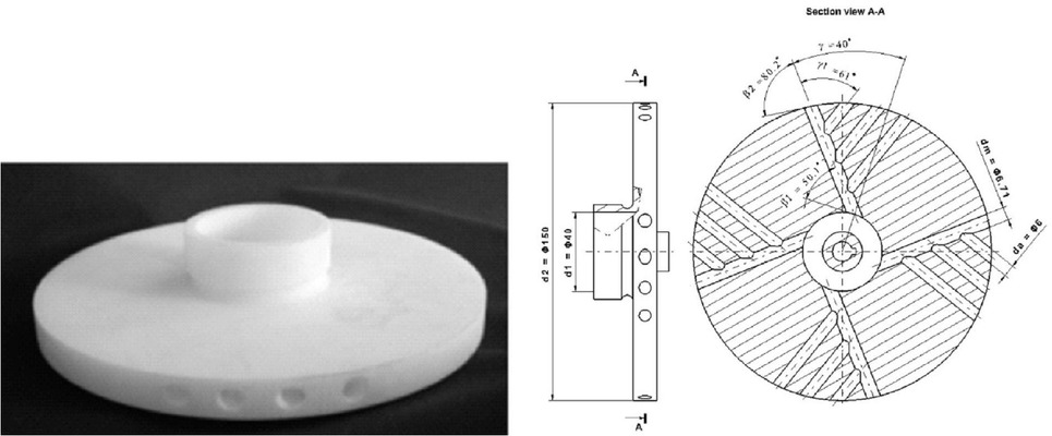
Geometry of the impeller 1 (I1)
Impeller 2 (I2). The second one (I2) was multi-piped impeller, designed according to patent [6]. Such structure was described in detail in [9]. The shape and basic parameters were presented in Figure 2.
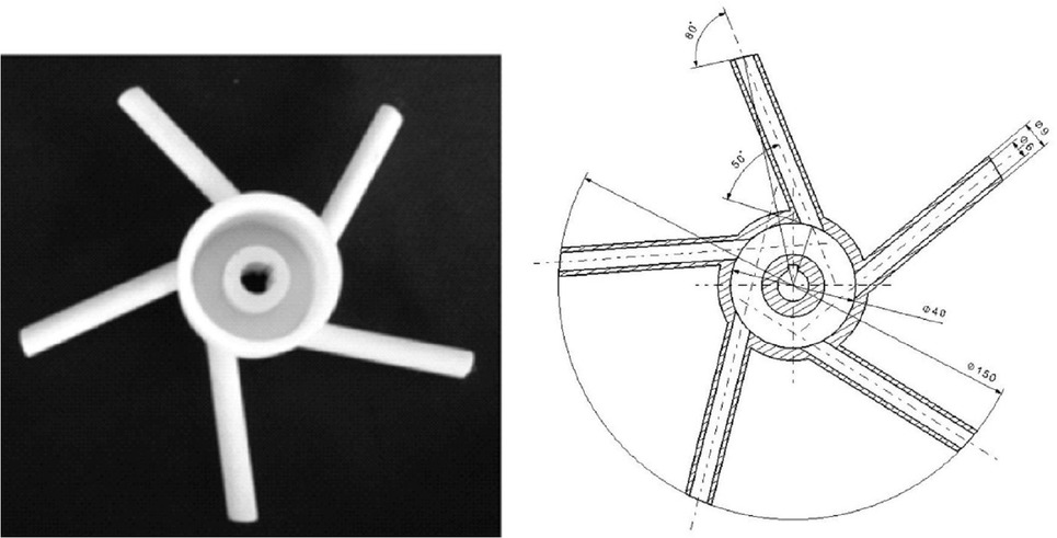
Geometry of the impeller 2 (I2)
Impeller 3 (I3). Impeller 3 is a modification of Impeller 2where the number of the channels (z) and external diameter (d2) were decreased to z =4 and d2=130 mm respectively.The model was shown in the Figure 3.
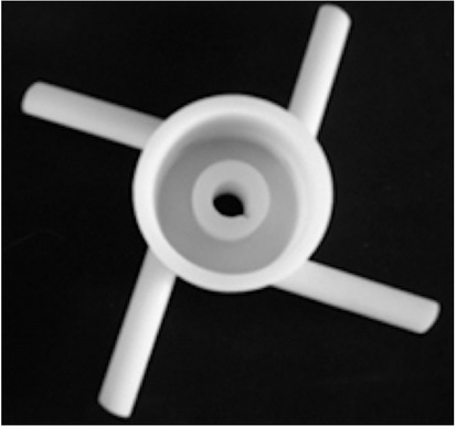
Geometry of the impeller 3 (I3)
Impeller 4 (I4). Impeller 4 is a modification of Impeller 2 concept where the pipes that create impeller passages were bended in such way in order to obtain optimal values of the inlet and outlet angles. The number of passages is z = 4, inlet angle β1 = 50 deg., outlet angle β2 = 30 deg.

Geometry of the impeller 4 (I4)
3 Test rig
In order to conduct investigation, a specialized test rig - presented in Figure 5 - was designed and constructed [9]. The main element of the test rig is a pump (Figure 5b) with a special design allowing for the quick replacement of the tested impellers while maintaining the repeatability of the measurement results.
![Figure 5 View of the test rig [9]](/document/doi/10.1515/eng-2019-0032/asset/graphic/j_eng-2019-0032_fig_005.jpg)
View of the test rig [9]
The pump is supplied from a closed tank where - depending upon the needs - one can generate overpressure or negative pressure and control the medium level and temperature.
The pump capacity can be adjusted with a ball control valve, namely MARS 88V with an IntrOM OM-1 electric drive. The measuring instruments which parameters are presented in Table 2 were used for measuring the specific values.
Measuring instruments [9]
| No | Measuring instrument | Range | Accuracy class |
|---|---|---|---|
| 1 | Electromagnetic flow meter Arkon | 0.18 – 17.67 m3/h | 0.2% |
| MAGS1-ST DN25 PN 40 | (0.1 – 10 m/s) | ||
| 2 | Pressure Gauge (suction) FUJI FKP 01 | −0.7 – 0.5 bar | 0.1% |
| 3 | Pressure Gauge (discharge) FUJI FKP 03 | 0 – 30 bar | 0.1% |
| 4 | Active Power Transducer METROL PP73 | 0 – 3000 W | 0.3% |
| 5 | Temperature Transducer FLEXTOP 2202 | 0 – 50∘C | ± 0.9∘C |
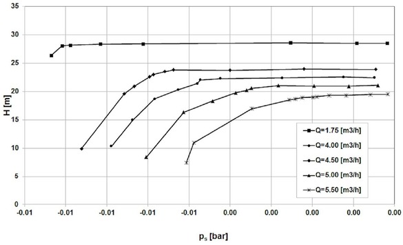
The characteristics of the tested impeller were measured in a fully automated way, according to the recommendations given in EN IS0 9906:2000. The measurement process is controlled by a computer and dedicated software. The test rig gives possibility of cavitation research by means of three methods:
generation vacuum in the tank,
decrease water level in the tank,
throttling at the suction pipeline.
The third method (throttling at the suction pipeline) was selected as the fastest and which generated accuracy on the acceptable level.
4 Result of the measurements
The basic parameters were determined according to following formulas:
Pump head:
Hydraulic power:
Pump efficiency
Net Positive Suction Head
Required Net Positive Suction Head
Based on data presented in Table 1 the average measurement uncertainness were determined as follows:
for pump head ΔH = 4%,
for hydraulic power ΔP = 8%,
for NPSH ΔNPSH = 3%.
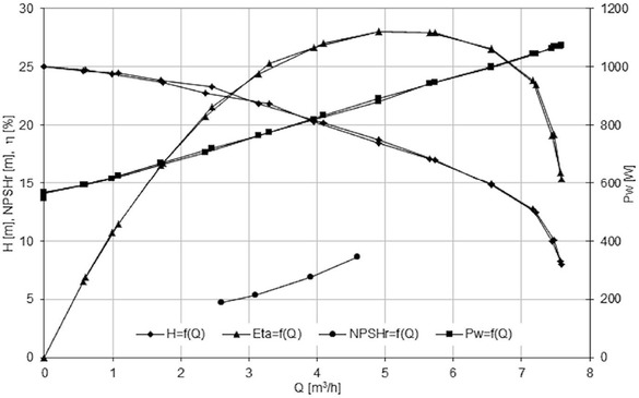
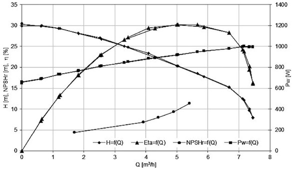
The results of the measurements are presented in the Figures 6-13.
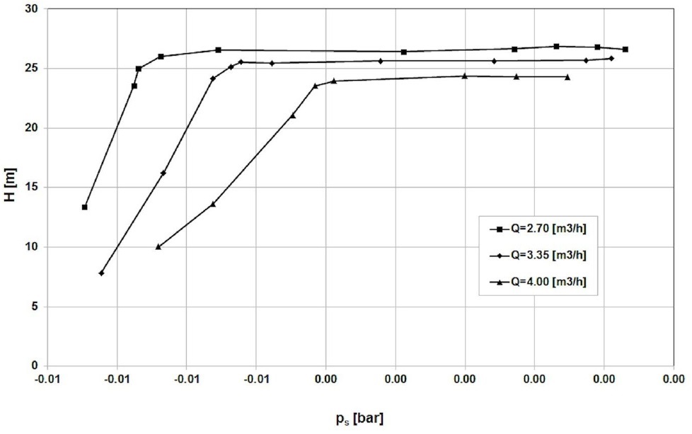
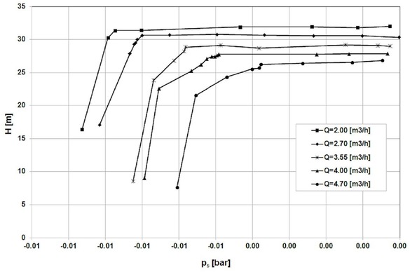
Cavitation curves of the Impeller 1
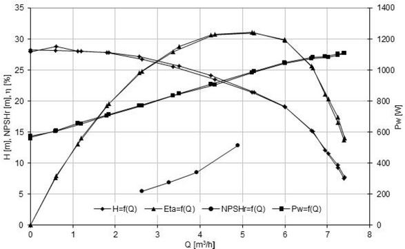
Characteristics of the Impeller 1
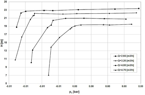
Cavitation curves of the Impeller 2
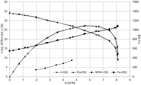
Characteristics of the Impeller 2
Cavitation curves of the Impeller 3
Characteristics of the Impeller 3
Cavitation curves of the Impeller 4
Characteristics of the Impeller 4
5 CFD modeling
In order to better understand cavitation behavior of the investigated impellers, the CFD calculations were performed for all impellers. The main aim of this calculations was to determine the static pressure distribution and to evaluate the pressure drop. Due to this fact, analysis were done without multiphase model. General description of the numerical model, applied grid, boundary conditions and rules of CFD modeling in detail one can find in [9]. In the Figures 14-17 the static pressure distribution was presented.
![Figure 14 Static pressure distribution [Pa] in Impeller 1](/document/doi/10.1515/eng-2019-0032/asset/graphic/j_eng-2019-0032_fig_014.jpg)
Static pressure distribution [Pa] in Impeller 1
Based on the results presented above, we can formulate the following conclusions:
Only impeller 2 achieved the assumed operating parameters (Table 1).
The maximal efficiency was reached by impeller 1 and impeller 4, respectively.
For the flow rate Q=4.5 m3/h, the best cavitation performance achieved impeller 4 (NPSHr = 8m), the worst – Impeller 1 (NPSHr=10.5 m).
The lowest value of NPSHr=8m(Impeller 4) is much higher than expected for classical centrifugal impeller (NPSHr=5.5 m– value obtained from author’s research).
The shapes of the cavitation curves are typical for classical centrifugal impellers and double elbows do not appear as for impellers with large inlet attack angle [10].
Based on presented results, we can formulate following conclusions:
In case of Impeller 1 additional pressure drop is observed in the inlet to the first side hole. This is the reason of the worst cavitation performance.
The Impellers 3 and 4 have better cavitation performance than Impeller 2 (Figure 15). This confirms assumption that impellers with lower number of passages and larger area of the inlet cross-section work better (lower pressure drop at the inlet section – Figures 16-17).
![Figure 15 Static pressure distribution [Pa] in Impeller 2](/document/doi/10.1515/eng-2019-0032/asset/graphic/j_eng-2019-0032_fig_015.jpg)
Static pressure distribution [Pa] in Impeller 2
![Figure 16 Static pressure distribution [Pa] in Impeller 3](/document/doi/10.1515/eng-2019-0032/asset/graphic/j_eng-2019-0032_fig_016.jpg)
Static pressure distribution [Pa] in Impeller 3
![Figure 17 Static pressure distribution [Pa] in Impeller 4](/document/doi/10.1515/eng-2019-0032/asset/graphic/j_eng-2019-0032_fig_017.jpg)
Static pressure distribution [Pa] in Impeller 4
6 Summary
Drilled impellers and multi-piped impellers are an interesting alternative for classical centrifugal impellers in the range of extremely low specific speed (nq<10). The values of the NPSHr for all investigated impellers are much higher than for classical centrifugal impellers. Among the researched impellers the best one was Impeller 4, that had 4 passages and the value of inlet angle β1 within the optimal range [10].
Acknowledgement
Calculations have been carried out using resources provided by Wroclaw Centre for Networking and Supercomputing (http://wcss.pl) grant No. 444.
Symbols
- cs
fluid velocity at section pipeline, m/s
- ct
fluid velocity at discharge pipeline, m/s
- g
gravity, m/s2
- H
pump head, m
- nq
kinematic specific speed, rpm
- NPSHr
net positive suction head (required), m
- pb
barometric pressure, Pa
- pms
gauge pressure in the pump inlet, Pa
- pmt
gauge pressure in the pump outlet, Pa
- Pu
hydraulic power, W
- pv
fluid vapor pressure, Pa
- Pw
power on the pomp shaft, W
Greek symbols
- β1
impeller inlet angle, deg
- η
pump efficiency
- ρ
density, kg/m3
References
[1] Choi Y., Kurokawa J., Matsui J., Imamura H., Internal flow characteristics of a centrifugal pump with very low specific speed, XXI st IAHR Symposium on Hydraulic Machinery and Systems, Lausanne, 2002, 1–7Suche in Google Scholar
[2] Kagawa S., Choi Y., Kurokawa J., Matsumi J., Performance of very low specific speed centrifugal pumps with circular casing. J. of Fluid Sci. Technol., 2007, 2(1), 130-138. DOI: 10.1299/jfst.2.13010.1299/jfst.2.130Suche in Google Scholar
[3] Kurokawa J., Yamada T., Hiraga H., Performance of low specific speed pumps, 11th Australasian Fluid Mechanics Conference, (1992, Australia, Hobart), Hobart, 1992, 861–864Suche in Google Scholar
[4] Gulich J, Centrifugal Pumps, Springer, Berlin, 2008Suche in Google Scholar
[5] Zhewen W., Round-disc through-hole ultra-low ratio rotary speed centrifugal pump, Patent CN101021215, 2007Suche in Google Scholar
[6] Skrzypacz J., Wirnik pompy wirowej (Impeller of rotodynamic pump), Patent PL 86135, 2008Suche in Google Scholar
[7] Skrzypacz J., Analiza pracy pompy z wirnikiem otworowym (Analysis of a drilled impeller pump operation), Pompy Pompownie 2(2008), 32-34.Suche in Google Scholar
[8] Skrzypacz J., Wpływ parametrów geometrycznych wirnika otworowego na proces przekazywania energii (Influence of geometrical features of a drilled impeller on the energy transfer process). (2008, Przemysl, Poland), XII Międzynarodowa Konferencja Naukowo-Techniczna HERVICON, Przemyśl, 2008, 227-234.Suche in Google Scholar
[9] Skrzypacz J., Numerical modelling of flow phenomena in a pump with a multi-piped impeller, Chem. Eng. Processing: Process Intensification, 75, 2014, 58-66. DOI: 10.1016/j.cep.2013.11.003.10.1016/j.cep.2013.11.003Suche in Google Scholar
[10] Misiewicz A., Skrzypacz J., Cavitation behaviours of low specific speed pump impellers designed according to the "tight inlet" rule, Cent. Eur. J. Eng., 1(2), 2011, 195-201. DOI: 10.2478/s13531-011-0019-4.10.2478/s13531-011-0019-4Suche in Google Scholar
© 2019 J. Skrzypacz and M. Bieganowski, published by De Gruyter
This work is licensed under the Creative Commons Attribution 4.0 International License.
Artikel in diesem Heft
- Regular Article
- Exploring conditions and usefulness of UAVs in the BRAIN Massive Inspections Protocol
- A hybrid approach for solving multi-mode resource-constrained project scheduling problem in construction
- Identification of geodetic risk factors occurring at the construction project preparation stage
- Multicriteria comparative analysis of pillars strengthening of the historic building
- Methods of habitat reports’ evaluation
- Effect of material and technological factors on the properties of cement-lime mortars and mortars with plasticizing admixture
- Management of Innovation Ecosystems Based on Six Sigma Business Scorecard
- On a Stochastic Regularization Technique for Ill-Conditioned Linear Systems
- Dynamic safety system for collaboration of operators and industrial robots
- Assessment of Decentralized Electricity Production from Hybrid Renewable Energy Sources for Sustainable Energy Development in Nigeria
- Seasonal evaluation of surface water quality at the Tamanduá stream watershed (Aparecida de Goiânia, Goiás, Brazil) using the Water Quality Index
- EFQM model implementation in a Portuguese Higher Education Institution
- Assessment of direct and indirect effects of building developments on the environment
- Accelerated Aging of WPCs Based on Polypropylene and Plywood Production Residues
- Analysis of the Cost of a Building’s Life Cycle in a Probabilistic Approach
- Implementation of Web Services for Data Integration to Improve Performance in The Processing Loan Approval
- Rehabilitation of buildings as an alternative to sustainability in Brazilian constructions
- Synthesis Conditions for LPV Controller with Input Covariance Constraints
- Procurement management in construction: study of Czech municipalities
- Contractor’s bid pricing strategy: a model with correlation among competitors’ prices
- Control of construction projects using the Earned Value Method - case study
- Model supporting decisions on renovation and modernization of public utility buildings
- Cements with calcareous fly ash as component of low clinker eco-self compacting concrete
- Failure Analysis of Super Hard End Mill HSS-Co
- Simulation model for resource-constrained construction project
- Getting efficient choices in buildings by using Genetic Algorithms: Assessment & validation
- Analysis of renewable energy use in single-family housing
- Modeling of the harmonization method for executing a multi-unit construction project
- Effect of foam glass granules fillers modification of lime-sand products on their microstructure
- Volume Optimization of Solid Waste Landfill Using Voronoi Diagram Geometry
- Analysis of occupational accidents in the construction industry with regards to selected time parameters
- Bill of quantities and quantity survey of construction works of renovated buildings - case study
- Cooperation of the PTFE sealing ring with the steel ball of the valve subjected to durability test
- Analytical model assessing the effect of increased traffic flow intensities on the road administration, maintenance and lifetime
- Quartz bentonite sandmix in sand-lime products
- The Issue of a Transport Mode Choice from the Perspective of Enterprise Logistics
- Analysis of workplace injuries in Slovakian state forestry enterprises
- Research into Customer Preferences of Potential Buyers of Simple Wood-based Houses for the Purpose of Using the Target Costing
- Proposal of the Inventory Management Automatic Identification System in the Manufacturing Enterprise Applying the Multi-criteria Analysis Methods
- Hyperboloid offset surface in the architecture and construction industry
- Analysis of the preparatory phase of a construction investment in the area covered by revitalization
- The selection of sealing technologies of the subsoil and hydrotechnical structures and quality assurance
- Impact of high temperature drying process on beech wood containing tension wood
- Prediction of Strength of Remixed Concrete by Application of Orthogonal Decomposition, Neural Analysis and Regression Analysis
- Modelling a production process using a Sankey diagram and Computerized Relative Allocation of Facilities Technique (CRAFT)
- The feasibility of using a low-cost depth camera for 3D scanning in mass customization
- Urban Water Infrastructure Asset Management Plan: Case Study
- Evaluation the effect of lime on the plastic and hardened properties of cement mortar and quantified using Vipulanandan model
- Uplift and Settlement Prediction Model of Marine Clay Soil e Integrated with Polyurethane Foam
- IoT Applications in Wind Energy Conversion Systems
- A new method for graph stream summarization based on both the structure and concepts
- “Zhores” — Petaflops supercomputer for data-driven modeling, machine learning and artificial intelligence installed in Skolkovo Institute of Science and Technology
- Economic Disposal Quantity of Leftovers kept in storage: a Monte Carlo simulation method
- Computer technology of the thermal stress state and fatigue life analysis of turbine engine exhaust support frames
- Statistical model used to assessment the sulphate resistance of mortars with fly ashes
- Application of organization goal-oriented requirement engineering (OGORE) methods in erp-based company business processes
- Influence of Sand Size on Mechanical Properties of Fiber Reinforced Polymer Concrete
- Architecture For Automation System Metrics Collection, Visualization and Data Engineering – HAMK Sheet Metal Center Building Automation Case Study
- Optimization of shape memory alloy braces for concentrically braced steel braced frames
- Topical Issue Modern Manufacturing Technologies
- Feasibility Study of Microneedle Fabrication from a thin Nitinol Wire Using a CW Single-Mode Fiber Laser
- Topical Issue: Progress in area of the flow machines and devices
- Analysis of the influence of a stator type modification on the performance of a pump with a hole impeller
- Investigations of drilled and multi-piped impellers cavitation performance
- The novel solution of ball valve with replaceable orifice. Numerical and field tests
- The flow deteriorations in course of the partial load operation of the middle specific speed Francis turbine
- Numerical analysis of temperature distribution in a brush seal with thermo-regulating bimetal elements
- A new solution of the semi-metallic gasket increasing tightness level
- Design and analysis of the flange-bolted joint with respect to required tightness and strength
- Special Issue: Actual trends in logistics and industrial engineering
- Intelligent programming of robotic flange production by means of CAM programming
- Static testing evaluation of pipe conveyor belt for different tensioning forces
- Design of clamping structure for material flow monitor of pipe conveyors
- Risk Minimisation in Integrated Supply Chains
- Use of simulation model for measurement of MilkRun system performance
- A simulation model for the need for intra-plant transport operation planning by AGV
- Operative production planning utilising quantitative forecasting and Monte Carlo simulations
- Monitoring bulk material pressure on bottom of storage using DEM
- Calibration of Transducers and of a Coil Compression Spring Constant on the Testing Equipment Simulating the Process of a Pallet Positioning in a Rack Cell
- Design of evaluation tool used to improve the production process
- Planning of Optimal Capacity for the Middle-Sized Storage Using a Mathematical Model
- Experimental assessment of the static stiffness of machine parts and structures by changing the magnitude of the hysteresis as a function of loading
- The evaluation of the production of the shaped part using the workshop programming method on the two-spindle multi-axis CTX alpha 500 lathe
- Numerical Modeling of p-v-T Rheological Equation Coefficients for Polypropylene with Variable Chalk Content
- Current options in the life cycle assessment of additive manufacturing products
- Ideal mathematical model of shock compression and shock expansion
- Use of simulation by modelling of conveyor belt contact forces