Static and dynamic analyses of auxetic hybrid FRC/CNTRC laminated plates
-
Xu-Hao Huang
 ,
Iftikhar Azim
,
Iftikhar Azim

Abstract
In this work, a hybrid laminated plate is developed by changing ply orientations and stacking sequences. The hybrid laminated plate is composed of carbon nanotube reinforced composite and fiber reinforced composite layers. Negative Poisson’s ratio (NPR) is obtained for the case of [22F/(22C/−22C)3T/−22F] laminate. A theoretical laminated model considering geometric nonlinearity and shear deformation is presented. Based on a two-step perturbation method, the solutions of the motion equations are obtained to capture the nonlinear frequencies and load–deflection curves. On this basis, the fourth-order Runge–Kutta method is used to obtain the dynamic response of hybrid laminated plates. The presented model is verified by comparing the results obtained analytically and numerically. Several factors such as loading and distribution of carbon nanotubes (CNTs), and foundation type are considered in parametric study. Numerical results indicate that the thermal-mechanical behavior of hybrid laminated plates significantly improved by properly adjusting the CNT distribution. In addition, the results reveal that changes in temperature and foundation stiffness have pronounced influence on the nonlinear vibration characteristics of hybrid laminate plates with NPR as compared to those with positive Poisson’s ratio.
1 Introduction
Structures made from auxetic materials are becoming important in many industries because of the inherent excellent properties of these materials. Because of developments in the manufacturing technology, various auxetic materials and structures are developed and fabricated nowadays [1,2,3]. Ren et al. [4] performed a systematic review of these structures. Recently, the studies on the design and mechanical analyses have propelled to achieve improvements in the mechanical properties of the auxetic structures such as impact resistance [5,6,7] and energy absorption [8,9]. Furthermore, these structural elements require high reliability in their service life as the plates easily damage under different loading scenarios. For a safe design, the necessity of accurate evaluation of the mechanical behaviors of such plates is becoming inevitable. The characterization of the static and dynamic response is also required to estimate the frequencies and deflections of auxetic plates under different environmental scenarios. A number of studies have been dedicated to these structures. Particularly, investigations were made to study the bending [10,11], dynamic [12,13], and buckling behavior [13,14,15] of these structures. However, in these researches [10,11,12,13,14,15], the value of the negative Poisson’s ratios (NPRs) for estimating the effect of auxetic feature on the mechanical behavior of a plate is based on an assumption.
In the design of auxetic laminates, the concept of engineering constants is usually introduced to characterize the effective performance of these laminates. Evans et al. [16] found that effective NPR can be obtained by adjusting layup sequences in the laminates. Zhang et al. [17] also found that both the layup sequence and anisotropic material are necessary for structures to exhibit an NPR. In addition, many investigations are conducted regarding fiber reinforced composite (FRC) laminates with NPR. Herakovich [18] studied the auxetic behavior of (±θ)s laminates and found that the NPR of (±25)s laminate is −0.21. Hine et al. [19] observed that composites made with a high modulus carbon fiber are obtained to exhibit NPR value of v
23 of 0.5. Matsuda et al. [20] reported that the maximum amplitude of NPR in FRC laminates was close to −0.7 when the laying angle is 25°. Harkati et al. [21,22] investigated the effect of material properties on
FRCs are applied in the design of laminates with NPR. Compared with FRCs, carbon nanotube reinforced composite (CNTRC) has the advantages of high strength and strong anisotropy. In addition, functionally graded (FG) materials are frequently used in many fields. Combining the concept of FG with carbon nanotubes (CNTs) can be used to improve the performance of CNTRC [24]. Based on the design of auxetic FRC laminates, this concept is applied to the design of FRC/CNTRC hybrid laminate with NPR. This hybrid laminate is made of FG-CNTRC core and FRC face sheets. Shen [24] proposed the concept of FG-CNTRC structures and studied the mechanical behavior of these structures at different scales. Thereafter, researches on the static and vibration response of FG-CNTRC structures were carried out [25,26,27,28,29]. Fan and Wang [27] used a theoretical model together with a finite element approach to analyze low-velocity impact response of the FG-CNTRC beams. Chen et al. [29] used the third-order piston theory to study the thermal buckling behavior of multi-scale hybrid laminated nanocomposite disk exposed to hygro-mechanical loading. Fu et al. [30,31] examined the dynamic instability of FG-CNTRC and FGM conical shells in the framework of first-order shear deformation theory. Yang and his coauthors studied the effects of out-of-plane NPR on the nonlinear flexural and dynamic behavior of FG-CNTRC structures [32,33]. Yu and Shen [34] investigated the nonlinear mechanical behavior of hybrid metal/CNTRC plate resting on elastic foundations. By considering the matrix cracks, Fan et al. [35,36] studied the static and dynamic characterizes of hybrid laminated structures made from either FRC or CNTRC. Lei et al. [37,38] investigated the influence of matrix cracks on the bending and vibration behavior of FRC/CNTRC plates using the element-free Galerkin method and self-consistent model. Further, the buckling behavior of these structures was examined by Lei and Yang [39]. Kamarian et al. [40] used the firefly algorithm for the optimization of fiber/CNT/polymer plates to maximize the natural frequency. Furthermore, the adoption of FRC/CNTRC hybrid concept was later extended to the design of composite blades by Zhang et al. [41,42]. They are concerned with the nonlinear vibration responses of hybrid composite blades. In addition, the studies of the hybrid laminated structures made with multi-materials can be found in ref. [43,44,45,46,47,48,49,50,51]. However, there are no studies available in literature that report the vibration and dynamic characteristics of auxetic FRC/CNTRC hybrid laminated plate.
In the present study, both FRC/CNTRC hybrid configurations and NPR are considered. The authors used Reddy Shear Deformation Theory with von Kármán nonlinear theory for bending, vibration, and forced vibration analyses of these structures. The motion equations are derived by considering temperature field and subgrade reaction of foundation. The effects of the CNT configuration, environmental conditions, and foundation type on the mechanical behavior of hybrid laminated plate with NPR or positive Poisson’s ratio (PPR) are assessed.
2 Theoretical modeling of hybrid laminates with NPR or PPR
2.1 Effective Poisson’s ratio for laminates
The global stiffness and strength of laminates depend on the ply orientation and stacking sequence. The effect of CNTs’ orientation angle on the instability characteristic of laminated plate is studied by Liew et al. [52] and Jam and Maghamikia [53]. It was assumed in these studies that reinforcing fibers are of sufficient length to be laid in at different angles. The same assumption is also considered in the current work.
Sun and Li [23] presented a model for effective Poisson’s ratio (EPR) of symmetric laminates. This model cannot be applied for an arbitrary layup laminates. Unlike the Sun et al.’s model [23], the model proposed in this study considers the effect of bending and bending-extension coupling, and provide more accurate prediction of EPR of an arbitrary angle-ply laminates. Based on the classical laminate theory, the formulae for the EPR are obtained as follows:
where
Furthermore, the presented model has high generalization capacity because it can be used to design symmetric laminates as well as laminates with asymmetric materials properties. In the current work, FRC/CNTRC hybrid laminate with NRP is developed. The hybrid laminated plates are modeled in the hinged condition with the following ply orientation and staking sequence: [θ F/(θ C/−θ C)3T/−θ F]. To facilitate the identification, the superscript F and C represent the layer of FRC and CNTRC, respectively. To predict the EPR of hybrid laminate, the material parameters of each layer are determined. Based on ref. [24] and [57], the general form for calculating these properties are given by Fan and Wang [36], which can be expressed as:
where the superscript r (r = CNT, F) means reinforcement and subscript m means matrix;
| T (K) |
|
|
|
|
|
|
|
|---|---|---|---|---|---|---|---|
| 300 | 5.6466 | 7.0800 | 1.9445 | 2.1000 | 3.4584 | 5.1682 | 4.500 |
| 400 | 5.5679 | 6.9814 | 1.9703 | 1.6300 | 4.1496 | 5.0905 | 4.725 |
| 500 | 5.5308 | 6.9348 | 1.9643 | 1.1600 | 4.5361 | 5.0189 | 4.950 |
| Volume fraction (V r ) | V CNT = 0.11 | V CNT = 0.14 | V CNT = 0.17 | V F = 0.6 |
|---|---|---|---|---|
| η 1 | 0.149 | 0.15 | 0.15 | 1 |
| η 2 | 0.934 | 0.941 | 0.941 | 1 |
| η 3 | 0.934 | 0.941 | 0.941 | 1 |
| η 4 | 0 | 0 | 0 | 1 |
The analytical solution mentioned above is capable of calculating the EPR of an arbitrary angle-ply laminate. A systematic investigation of the antisymmetric hybrid laminates is also carried out. Five configurations of laminated plates are considered as described in Table 3, and the uniform distribution (UD) is used as a reference. These configurations are for an identical material and have a constant thickness of 0.125 and 0.25 mm for FRC and CNT layers, respectively. Several types of CNT distributions are taken into consideration, which include the type of CNT volume fraction (V CNT) and the volume fraction of the fibers to be fixed as V F = 0.6 (see Figure 3(b)).
Configuration of CNT for FRC/CNTRC laminate plate
| Types of ply | UD | FG-X | FG-O | FG-
|
FG-V | Geometry of laminated plate |
|---|---|---|---|---|---|---|
| Ply1 | 0.6 | 0.6 | 0.6 | 0.6 | 0.6 |
 |
| Ply2 | 0.14 | 0.17 | 0.11 | 0.11 | 0.17 | |
| Ply3 | 0.14 | 0.14 | 0.14 | 0.11 | 0.17 | |
| Ply4 | 0.14 | 0.11 | 0.17 | 0.14 | 0.14 | |
| Ply5 | 0.14 | 0.11 | 0.17 | 0.14 | 0.14 | |
| Ply6 | 0.14 | 0.14 | 0.14 | 0.17 | 0.11 | |
| Ply7 | 0.14 | 0.17 | 0.11 | 0.17 | 0.11 | |
| Ply8 | 0.6 | 0.6 | 0.6 | 0.6 | 0.6 |
2.2 Design of auxetic hybrid laminate
An analytical example is given to show the correctness of the solutions mentioned above. Figure 1 shows the comparison of the solutions of the EPR (
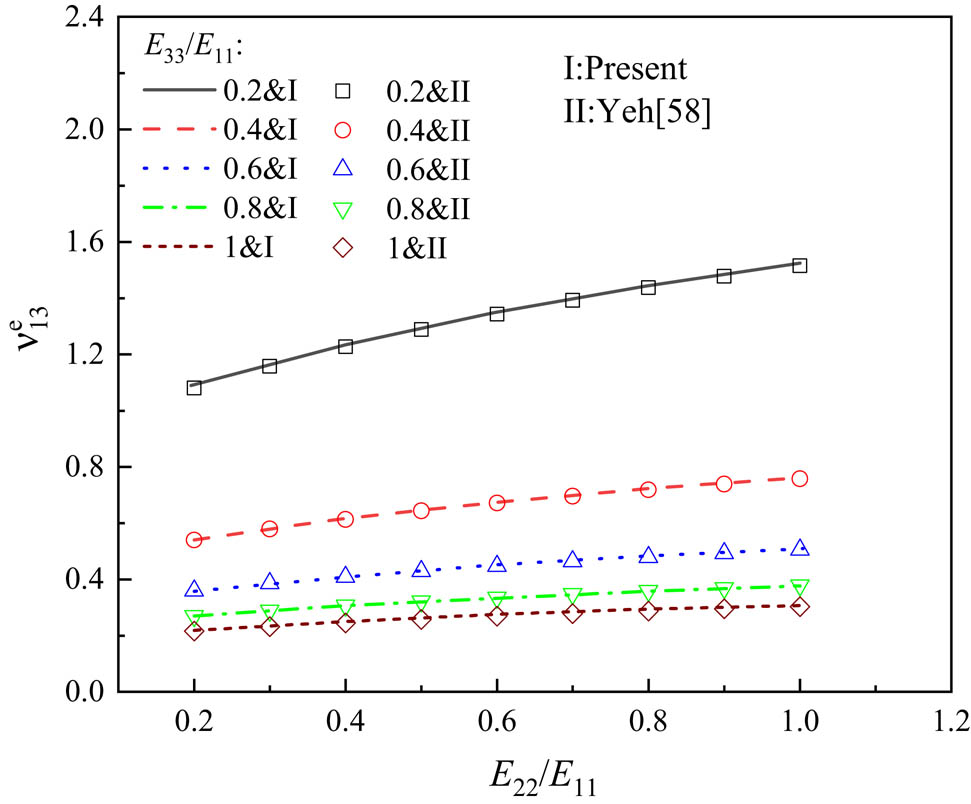
Effect of E
22/E
11 on the EPR (
Here, equation (1) is adopted to assess the effect of the ply orientations and FG configuration on the EPR (
![Figure 2
EPR (
v
13
e
{v}_{13}^{e}
)-laying angle for [θ
F/(θ
C/−θ
C)3T/−θ
F] laminated plates.](/document/doi/10.1515/ntrev-2020-0106/asset/graphic/j_ntrev-2020-0106_fig_002.jpg)
EPR (
EPR (
| FG- | [22F/(22C/−22C)3T/−22F] | [45F/(45C/−45C)3T/−45F] | ||||
|---|---|---|---|---|---|---|
| 300 K | 400 K | 500 K | 300 K | 400 K | 500 K | |
| UD | −0.479 | −0.580 | −0.723 | 0.025 | 0.020 | 0.015 |
| FG-V | −0.338 | −0.427 | −0.559 | 0.031 | 0.026 | 0.019 |
| FG-
|
−0.338 | −0.427 | −0.559 | 0.031 | 0.026 | 0.019 |
| FG-X | −0.416 | −0.515 | −0.658 | 0.028 | 0.023 | 0.017 |
| FG-O | −0.447 | −0.548 | −0.693 | 0.027 | 0.022 | 0.016 |
3 Theoretical modeling of nonlinear behavior
3.1 Motion equations
Laminates consist of layers of composites reinforced with CNTRC and FRC. Consider a hybrid laminated plate composed of eight layers with lamination scheme [θ
F/(θ
C/−θ
C)3T/θ
F] and resting on a continuous elastic and viscoelastic foundation as shown in Figure 3. Figure 3(a) defines the coordinate system used in the analysis of hybrid laminated plate analysis. The XYZ coordinate system is assumed to have its origin on the middle face of the plate, so that the middle surface lies in the XY-plane. The displacements at a point in the X, Y, and Z directions are
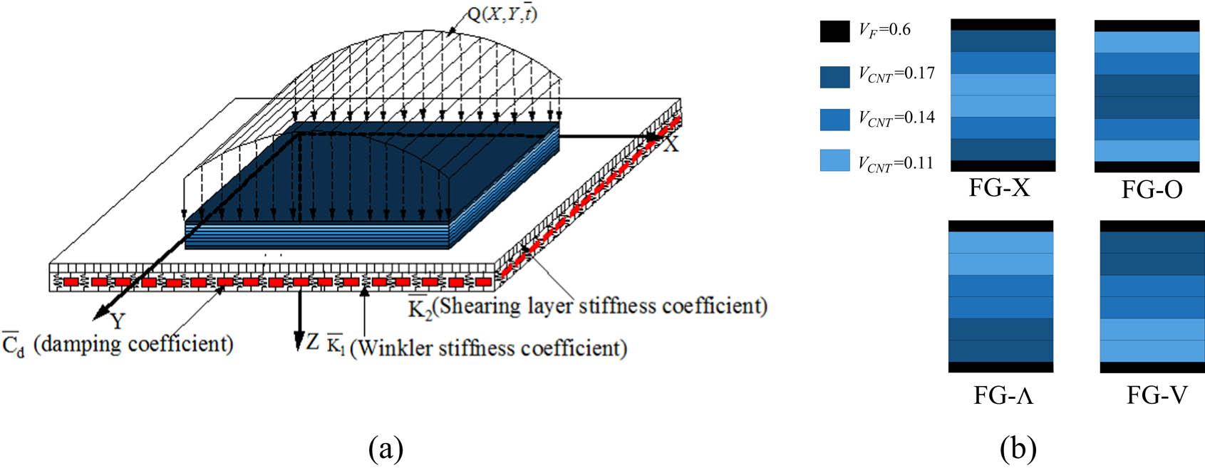
Coordinate system and various configurations of hybrid laminated plates.
The simply supported plate is surrounded by a visco-Pasternak foundation that consists of the Winkler foundation (
The method of analysis is based on the third-order shear deformation theory [59] for the laminated plate undergoing large deflection. The effect of the elevated temperature is considered by introducing thermal forces
where the nonlinear operator (
where
In the current work, simply supported boundary conditions (BCs) are used.
At X = 0, a:
At Y = 0, b:
where
The immovable in-plane BCs (12b) and (12d) are converted to integral form as given below:
where,
in which the reduced stiffnesses of plate (
The nonlinear motion equations for the forced vibration can be solved by a two-step perturbation approach proposed by Shen [60]. Equations (6)–(9) can be converted to dimensionless forms by the definition of the following dimensionless parameters as:
The non-dimensional parameters and nonlinear operator (L) in the equations (15)–(18) are given as follows:
in which the non-dimensional forms of foundation stiffnesses k
1, k
2 are only used in numerical calculations, E
0 and ρ
0 are reference values of matrix Young’s modulus E
m
and matrix density ρ
m
at room temperature, respectively.
In equations (15)–(18), the dimensionless linear operators (L ij ()) are defined as in Shen [60].
Substitution of dimensionless parameters into equations (14a–b) and (15a–b) yields:
At x = 0, a:
At y = 0, b:
where δ x and δ y are given as:
with γ ijk given in Shen [60].
3.2 Solutions for large amplitude vibration
The solutions for equations (15)–(18) consist of an additional and initial displacement terms as a result of the thermal stress. Here, we will only discuss the solution process of the first term. The solutions for the thermal bending can be derived in the same way [61]. The following initial BCs are used in this study:
Considering τ = εt, the equations can be expanded as a function with a small perturbation parameter ε i (1, 2, 3,…).
Next, an initially deflected hybrid plate is considered and solution of the first-order equation can be assumed to be:
where (m, n) are the half-wave number of vibration mode of plate along the X- and Y-directions, respectively.
Motions equations converted into their perturbation expansions are given from the substitution of solution equation (24) to equations (15)–(18). The perturbation solutions of the motion equations are given below:
In equations (26)–(30), τ is replaced back by t and
Substituting equation (31) into (30) and applying Galerkin procedure yield equation (33), which can be expressed as:
with g 40, g 41, etc. are given in equations (C.1)–(C.3) of the Appendix C, and
where
Impulsive shapes of dynamic loads
| Dynamic load | F 2(t) | |
|---|---|---|
| Sudden load | F 2(t) = 1 |
 |
| Step load | F 2(t) = 1, t < t 0 | |
| F 2(t) = 0, t > t 0 | ||
| Triangular load | F 2(t) = 1 − t/t 0, t < t 0 | |
| F 2(t) = 0, t > t 0 | ||
| Sinusoidal load | F 2(t) = sin(πt/t 0), t < t 0 | |
| F 2(t) = 0, t > t 0 | ||
| Exponential load | F 2(t) = e −ωt |
By solving equation (32), the relationship between deflection and time can be obtained to characterize the forced vibration. It can be easily converted to a free vibration problem by setting the load to zero. Therefore, the solution of the dimensionless nonlinear frequency (ω
NL) can be obtained by solving equation (21) with
where ω L is the dimensionless linear frequency.
3.3 Solutions for forced vibration
In addition to large amplitude and free vibration analysis, the forced vibration of hybrid laminated plates subjected to dynamic load (see Figure 3) is taken into consideration. The center deflection–time relationship is used to characterize the forced vibration of the plate. Therefore, the second-order ordinary differential equation (see equation 32) with initial value can be obtained using the fourth-order Runge–Kutta method. It is worth noting that the initial deflection for FG-Λ or FG-V will be triggered under the temperature field.
3.4 Solutions for nonlinear bending
In this section, the nonlinear bending response of hybrid laminated plates with NPR and PPR is studied. First, the relationship between the applied pressure and the deflection is determined. For the static analysis, this relationship is independent of the variation in time (t). Therefore, the dynamic load is modified to be static load and Q(X, Y, t) = q 0. Based on these assumptions and using a two-step perturbation approach, the solution of motion equations can be obtained as:
and
In equations (34)–(37), the second perturbation coefficient
It can be noted that
4 Numerical results and discussions
4.1 Validation studies
To verify the proposed model, results of the comparison analysis are reported. The results of four examples are given to validate the present model. Hybrid plates are assumed in the first, second, and fourth examples, whereas FG-CNTRC plates are adopted in the third example.
Comparison of the fundamental frequencies for [θ C/90F]2 plates
| VCN | b/h | ||||
|---|---|---|---|---|---|
| 10 | 20 | 50 | 100 | ||
| 0.12 | Fan and Wang [62] | 14.8861 | 16.7109 | 17.3677 | 17.4686 |
| Present | 14.6569 | 16.6273 | 17.3523 | 17.4644 | |
| 0.17 | Fan and Wang [62] | 16.2484 | 18.2019 | 18.8970 | 19.0034 |
| Present | 16.0858 | 18.1115 | 18.8874 | 19.0072 | |
| 0.28 | Fan and Wang [62] | 17.6812 | 20.2276 | 21.1827 | 21.3314 |
| Present | 17.3354 | 20.0948 | 21.1646 | 21.3332 | |

Comparisons of ω NL/ω L for angle-ply (0/90)3T laminated plate.

Comparison of forced vibration curves for UD and FG-X laminated plate.
![Figure 6
Comparison of load–deflection relationships of [45C/−45F] plate.](/document/doi/10.1515/ntrev-2020-0106/asset/graphic/j_ntrev-2020-0106_fig_006.jpg)
Comparison of load–deflection relationships of [45C/−45F] plate.
Example 1
In this example, verification investigations of the free vibration of a simply supported [θ
C/90F]2 hybrid plate with a = 20h and h = 0.5 mm are presented. Table 6 presents the comparison of the solutions using an analytical model proposed by Fan and Wang [62] and the method presented in this study for a hybrid laminated plate. The two reinforced materials are FRC and CNTRC and the material properties are: (1) for FRC:
Example 2
This example is given to verify the correctness of the solution for nonlinear vibration of plate. The dimensions of the (0/90)3T plate are: a = 2b = 20 mm and h = 0.6 mm. Present frequency ratios are compared with those of Pillai and Rao [63] and Lai et al. [64] for a plate with
Example 3
The predicted dynamic response by the proposed model is compared to the numerical results predicted in detail by Liew et al. [65]. The CNTRC plates are set with a/h = 4 cm and b = a, whereas the material parameters are the same as in Example 1. As shown in Figure 5, the forced vibration curves are compared with the results predicted in ref. [65]. According to the curves plotted in Figure 5, similar trend can be observed between the results.
Example 4
The bending studies of a hybrid plate consisting of a cross-ply [45C/−45F] with large deflection are reported by Fan and Wang [66]. A hybrid plate subjected to a uniform and sinusoidal load is considered in the analysis. Constituent materials of the plate are same as in the case of hybrid plates listed in Figure 6. The results of the present dimensionless deflections are compared with those in ref. [66]. As plotted in Figure 6, the proposed results are very close to those presented by Fan and Wang [66].
4.2 Linear vibration analysis
In this subsection, the effects of the change in temperature, CNT distribution pattern, and the foundation constants (k 1, k 2) on the free vibration of hybrid laminated plates are scrutinized. Unless otherwise specified, the angle-ply (22F/(22C/−22C)3T/22F) and (45F/(45C/−45C)3T/45F) hybrid laminated plates are adopted in the following studies.
The effect of thermal environments on the first six frequencies

Natural frequencies
The values of the stiffnesses in the framework of Pasternak foundation for different distributions of CNT are shown in Figure 7(d) and (e). Two different foundation coefficients (k 1, k 2) are considered, i.e., (102, 10), (102, 0). It should be noted that structures with (k 1, k 2) = (0, 0) are selected as reference examples and can be found in Figure 7(a). As shown, the natural frequencies of the hybrid laminated plate for higher (k 1, k 2) are greater than the other cases.
4.3 Large amplitude vibration
The nonlinear vibration analysis of hybrid plates is carried out. A non-dimensional frequency ratio (ω NL/ω L) is considered. The frequency ratio–deflection relationships obtained for hybrid laminated plates composed of CNTRC with different configurations are presented in Figure 8. As expected, FG-X has the lowest frequency ratio, whereas the FG-O has the highest frequency ratio. The frequency ratios for the plate with Λ and V pattern are similar. It shows that the overall stiffness of the plates increases as the CNT volume fraction in the surface layer is increased.

Amplitude curves for hybrid plates with NPR or PPR.
Furthermore, nonlinear frequencies are predicted for UD and FG-X plates subjected to temperatures in the range of 300–500 K. Looking at the curves shown in Figure 9, one can see that an increase in the thermal stress leads to an increase in the frequency ratio. It is found that laminated plates with NPR are more sensitive to temperature changes than plates with PPR.

Effect of T on nonlinear vibration for hybrid plates.
The frequency ratio of UD and FG-X plates with and without considering elastic foundations are obtained as shown in Figure 10. The foundation coefficients are taken as (k 1, k 2) = (0, 0), (103, 0), (103, 10). From Figure 10, it is concluded that the increase in foundation stiffness makes the plate more rigid when the foundation coefficients of the plate are increased. This also leads to an increase in the frequency ratio of the UD and FG-X. It can also be seen that (22F/(22C/−22C)3T/−22F) laminated plates are more sensitive to change in foundation stiffnesses than those with (45F/(45C/−45C)3T/−45F).

Effect of foundation coefficient on nonlinear vibration for hybrid plates.
4.4 Forced vibration analysis
Hybrid plates with NPR subjected to dynamic load are investigated in this section. Different dynamic loads are adopted to make a comparison and calculate the one corresponding to the maximum deflection of the plate. Except for a sudden load, it is assumed that the duration of the dynamic load is equal to the period of forced vibration. As shown in Figure 11, a comparison of the forced vibration of (22F/(22C/−22C)3T/−22F) plate with a = b = 20h and h = 35 mm subjected to different dynamic loads is proposed. It can be found that the same amplitude does not mean the same defection of the applied load (Figure 11(b)). The highest defection is predicted for step load during forced vibration. While analyzing the free vibration of plate, one can find that the highest increment of defection for the same duration takes place for the triangular load. Unless otherwise specified, a sudden uniform load is considered in the following forced vibration studies.
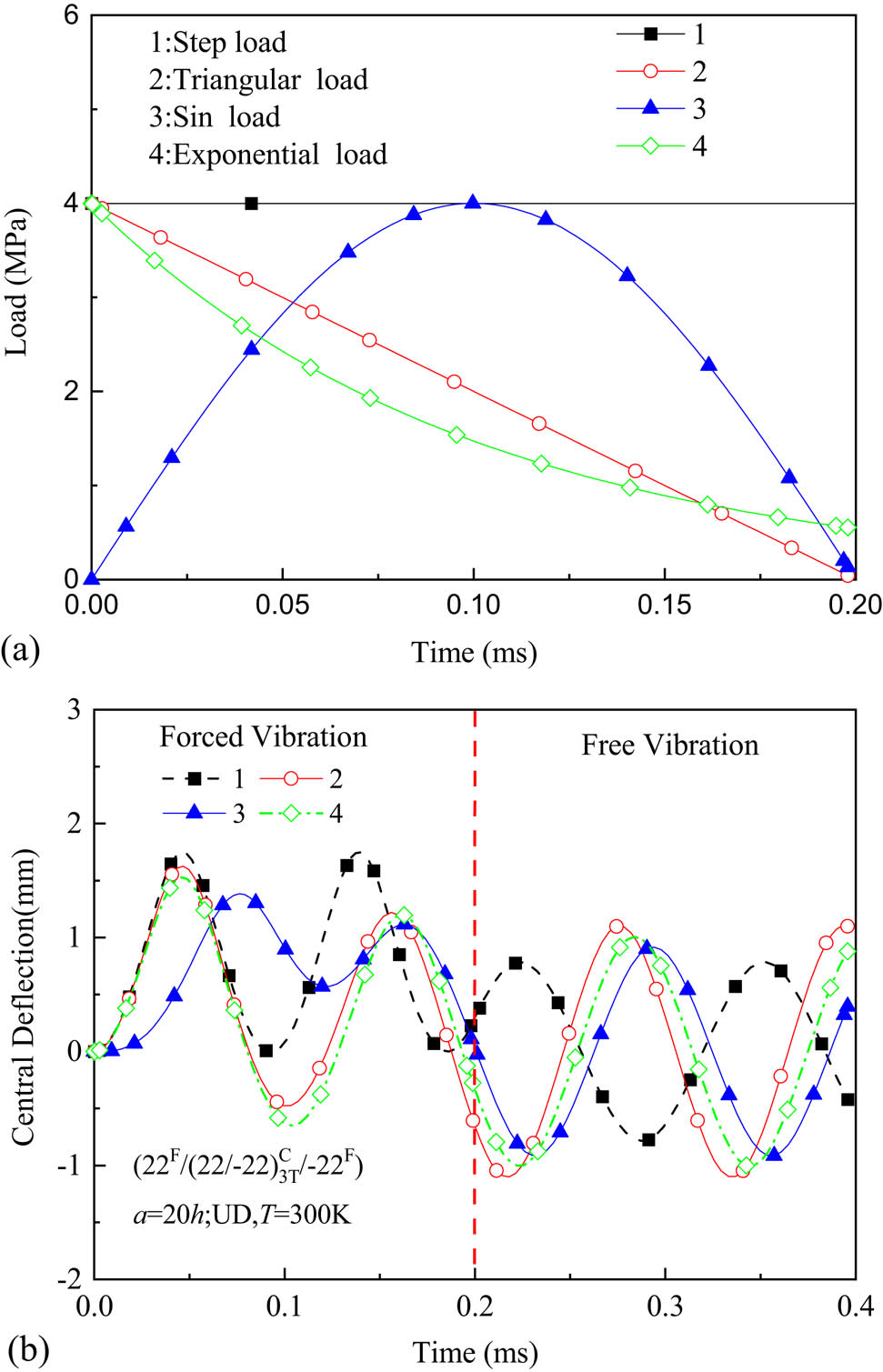
Effect of dynamic load on forced vibration of hybrid plates. (a) Type of dynamic loads. (b) Vibration curves
Five different configurations present above are taken into consideration. The CNT distributions between the central deflection and the time t are analyzed under the reference temperature, and the corresponding curves are shown in Figure 12(a) and (b). Unless otherwise specified, the amplitude of the load is fixed at 4 MPa. As expected, the type of FG configurations has a considerable effect on the forced vibration. Furthermore, FG-X exhibits great stiffness, which can be attributed to the increased V CN near the top and bottom layers. Thus, for the next parametric analysis, the studying examples are taken as UD and FG-X.
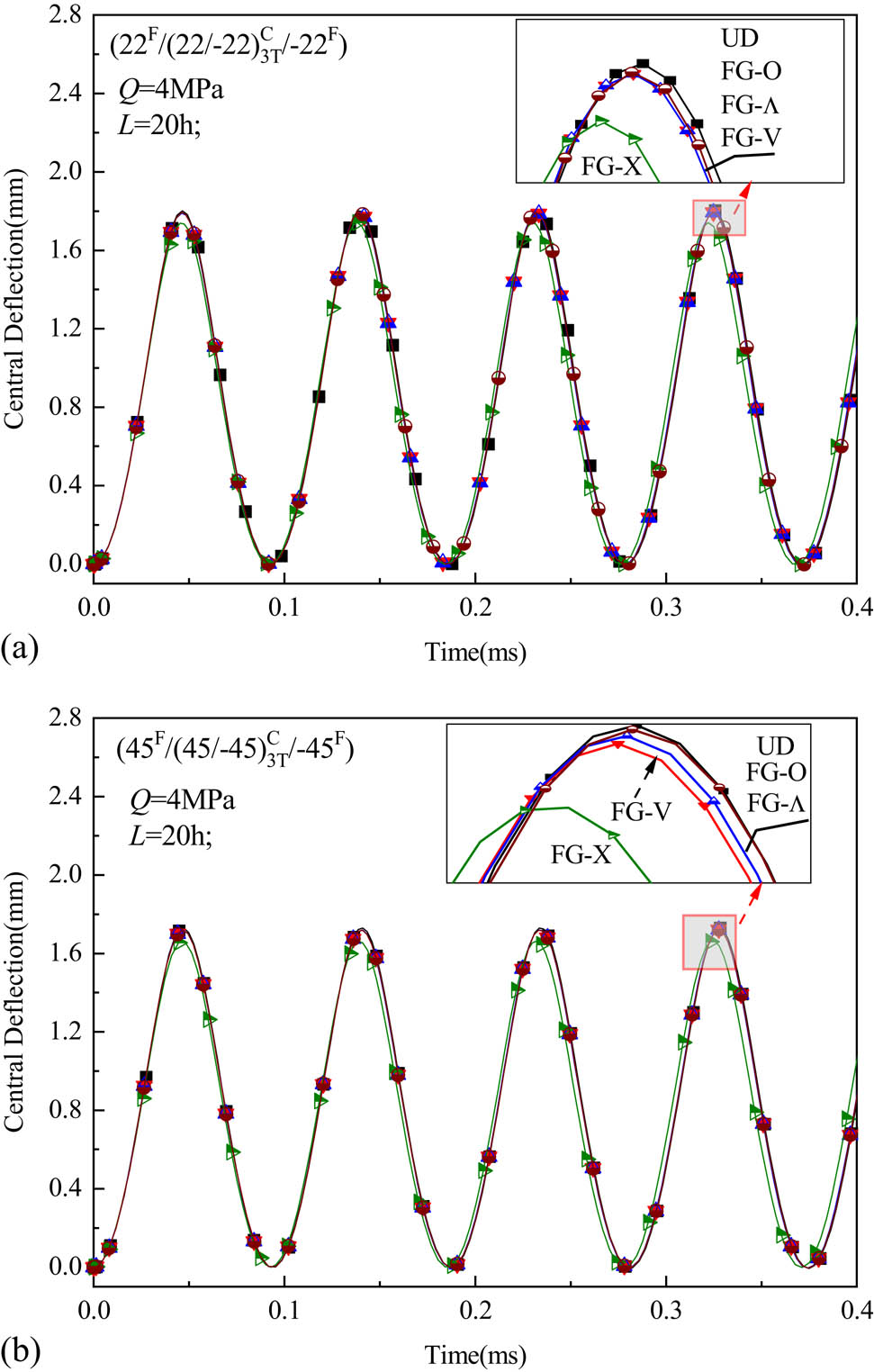
Forced vibration curves for FG hybrid plates.
In Figure 13(a) and (b), the influence because of variation in thermal stress is considered in the forced vibration of the UD and FG-X plates. The applied uniform load is adopted as 4 MPa for (22F/(22C/−22C)3T/−22F) and (45F/(45C/−45C)3T/−45F) with L = 20h. It is found that the defection and period of plate increase with increase in thermal stress. In fact, this phenomenon may be attributed to reduction in the overall stiffness of the plates under thermal environment.
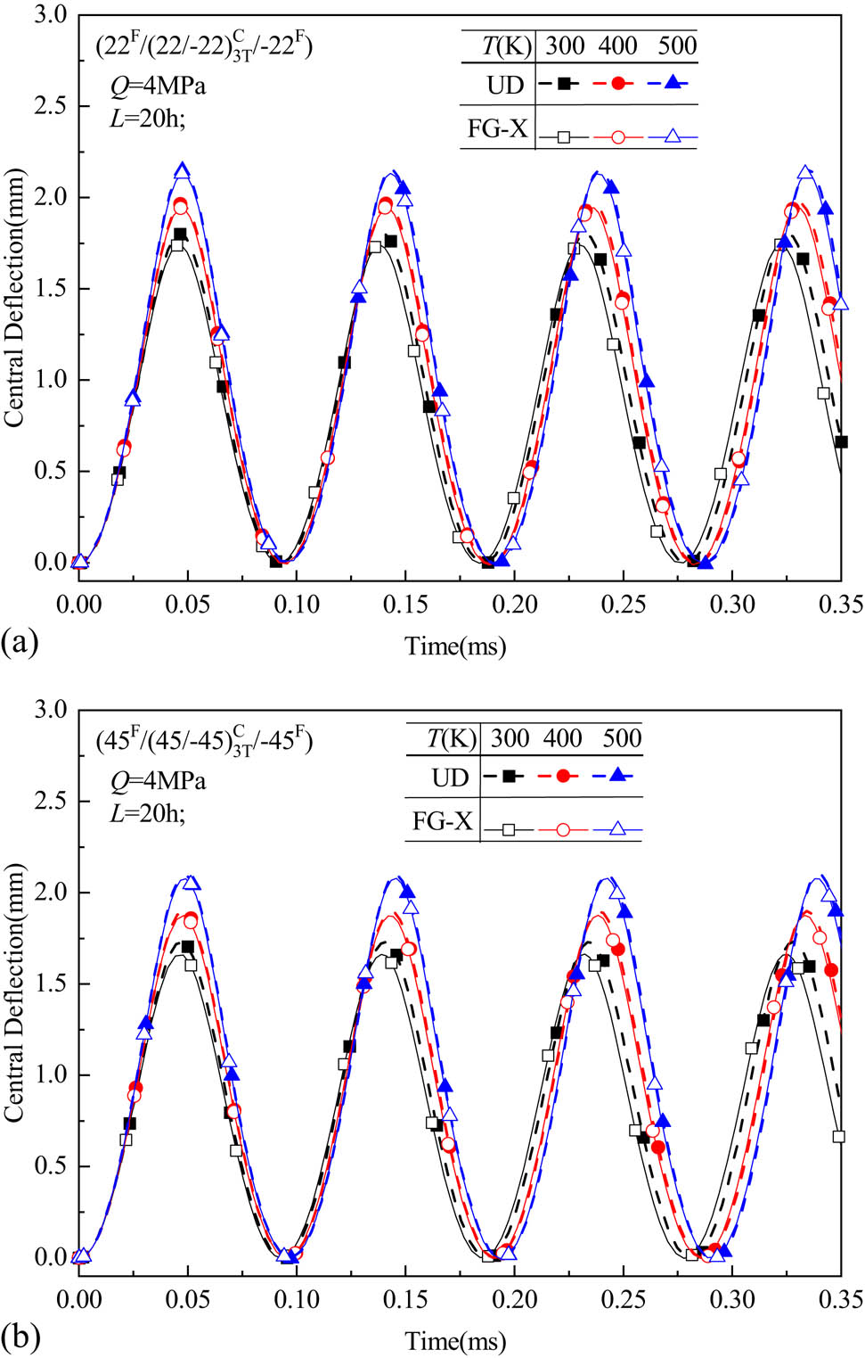
Effect of T on forced vibration of hybrid laminated plates (T = 300, 400, and 500 K).
Figure 14(a) and (b) show the variation in maximum deflections with time for hybrid plates (22F/(22C/−22C)3T/−22F) and (45F/(45C/−45C)3T/−45F) for different foundation stiffnesses, but for the same temperature. To evaluate the influence of Pasternak and viscoelastic foundation, the plates with k 1 = k 2 = C d = 0 are adopted for comparative analysis. It appears that the dynamic behavior of the plates depends significantly on the values of the foundation coefficients. For example, the value of central deflections decreases with an increase in the foundation coefficient. The reinforcement effect of viscoelastic foundation is more obvious as compared to elastic foundation. It means that the forced vibration of the hybrid laminated plates is significantly influenced by the viscoelastic parameter. Furthermore, the peak value of the central deflection decreases with increase in time.

Effect of foundation coefficients on forced vibration of hybrid plates.
4.5 Nonlinear bending analysis
Figure 15(a) and (b) illustrate the nonlinear bending curves for UD and FG-plates subjected to different loading scenarios. Under uniform and sinusoidal distribution load, it is found that the defection of FG-O plate is largest, followed by UD. In addition, FG-X plates exhibit the largest bearing capacity. This is because CNTs are distributed away from the interlayer to improve the bending stiffness of the plate. Therefore, in the following, exhaustive studies will be carried out to evaluate the bending performance of FG-X and UD subjected to UD load, and different environmental conditions.

Load versus deflection of hybrid laminated plate composed of different CNT distribution patterns.
To evaluate the influence of thermal environment on the bending characteristics of FRC/CNTRC hybrid plate, Figure 16(a) and (b) show the variations in the central deflection of UD and FG-X plates with L = 10h versus load for various temperature fields. It is easy to observe that the deflection of the hybrid laminated plates increases with increment of temperature. As a result, the effect of the degradation caused by temperature field should be considered in the design of bearing capacity of plates.

Effect of thermal field on bending behavior of hybrid laminated plates.
Figure 17(a) and (b) show the influence of the foundation coefficients on the bending behavior of UD and FG-X with room temperature and L = 20h. Three sets of values are selected for the stiffnesses of the elastic foundation ((k 1, k 2) = (0, 0), (102, 0), (102, 10)). As expected, the central deflection decreases when the foundation stiffness is increased.
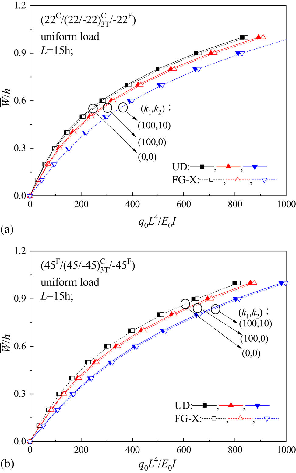
Effect of foundation coefficient on bending behavior of hybrid laminated plates.
5 Closing remarks
In this study, static and dynamic characteristics of hybrid plates fabricated from FRC layer and FG-CNTRC core resting on elastic foundation are studied. According to the arrangement of CNT, four FG distributions (
The following observations are summarized from the present study:
The configuration of CNTs has significant effect on the mechanical response of hybrid plate. The results show that FG-X arrangement exhibits minimum central deflection or nonlinear vibration frequency under the reference temperature. Moreover, FG-X configuration still shows excellent performance in thermal environment and foundation conditions.
It is observed that environmental conditions have a considerable effect on the frequency of plates. Increasing the foundation coefficients (k 1 , k 2) increases the frequencies of hybrid plates, whereas the elevated temperature effect plays an opposite role on the vibration behavior of these members.
In the case of nonlinear bending, vibration, and forced vibration behavior, increasing thermal stresses will increase the central deflection and nonlinear vibration frequency, whereas increasing the value of (k 1 , k 2) will lead to an opposite effect.
The most dangerous function shape loading is the step load. It gives the highest defection for all the analyzed cases. For viscoelastic foundation, a larger difference in the middle defection is visible for the duration greater than 0.5 ms.
The results of the parametric analysis reveal that the large amplitude vibration of (22F/(22C/−22C)3T/−22F) laminated plates is more sensitive to variation in the temperature and foundation stiffness as compared to those with (45F/(45C/−45C)3T/−45F).
Acknowledgments
The authors are grateful for the support from the Science Research Plan of Shanghai Municipal Science and Technology Committee under Grant 18DZ1205603, National Natural Science Foundation of China [Grant No. 52078293, 51908352, 51978330, 51808286], and Natural Science Foundation of Jiangsu Province [Grant No. BK20180710].
-
Conflicts of interest: The authors declare no conflict of interest regarding the publication of this paper.
References
[1] Grima JN , Gatt R , Ellul B , Chetcuti E. Auxetic behaviour in non-crystalline materials having star or triangular shaped perforations. J Non-Cryst Solids. 2010;356(37–40):1980–7.10.1016/j.jnoncrysol.2010.05.074Search in Google Scholar
[2] Ren X , Shen J , Ghaedizadeh A , Tian H , Min Xie Y. Experiments and parametric studies on 3D metallic auxetic metamaterials with tuneable mechanical properties. Smart Mater Struct. 2015;24(9):95016.10.1088/0964-1726/24/9/095016Search in Google Scholar
[3] Ren X , Shen J , Ghaedizadeh A , Tian H , Xie YM. A simple auxetic tubular structure with tuneable mechanical properties. Smart Mater Struct. 2016;25(6):65012.10.1088/0964-1726/25/6/065012Search in Google Scholar
[4] Ren X , Das R , Tran P , Ngo TD , Xie YM. Auxetic metamaterials and structures: a review. Smart Mater Struct. 2018;27(2):23001.10.1088/1361-665X/aaa61cSearch in Google Scholar
[5] Alderson KL , Coenen VL. The low velocity impact response of auxetic carbon fibre laminates. Phys Status Solidi B. 2008;245(3):489–96.10.1002/pssb.200777701Search in Google Scholar
[6] Zhou L , Zeng J , Jiang L , Hu H. Low-velocity impact properties of 3D auxetic textile composite. J Mater Sci. 2018;53(5):3899–914.10.1007/s10853-017-1789-8Search in Google Scholar
[7] Madke RR , Chowdhury R. Anti-impact behavior of auxetic sandwich structure with braided face sheets and 3D re-entrant cores. Compos Struct. 2020;236:111838.10.1016/j.compstruct.2019.111838Search in Google Scholar
[8] Chang Y , Ma P , Jiang G. Energy absorption property of warp-knitted spacer fabrics with negative Poisson’s ratio under low velocity impact. Compos Struct. 2017;182:471–7.10.1016/j.compstruct.2017.09.065Search in Google Scholar
[9] Li D , Yin J , Dong L , Lakes RS. Numerical analysis on mechanical behaviors of hierarchical cellular structures with negative Poisson’s ratio. Smart Mater Struct. 2017;26(2):25014.10.1088/1361-665X/26/2/025014Search in Google Scholar
[10] Lim TC. Shear deformation in rectangular auxetic plates. J Eng Mater Technol. 2014;136(3):1–6.10.1115/1.4027711Search in Google Scholar
[11] Behravan Rad A. Static analysis of non-uniform 2D functionally graded auxetic-porous circular plates interacting with the gradient elastic foundations involving friction force. Aerosp Sci Technol. 2018;76:315–39.10.1016/j.ast.2018.01.036Search in Google Scholar
[12] Chen X , Feng ZH. Dynamic behaviour of a thin laminated plate embedded with auxetic layers subject to in-plane excitation. Mech Res Commun. 2017;85:45–52.10.1016/j.mechrescom.2017.07.013Search in Google Scholar
[13] Asemi K , Shariyat M. Three-dimensional biaxial post-buckling analysis of heterogeneous auxetic rectangular plates on elastic foundations by new criteria. Comput Method Appl M. 2016;302:1–26.10.1016/j.cma.2015.12.026Search in Google Scholar
[14] Mansouri MH , Shariyat M. Differential quadrature thermal buckling analysis of general quadrilateral orthotropic auxetic FGM plates on elastic foundations. Thin Wall Struct. 2017;112:194–207.10.1016/j.tws.2016.12.018Search in Google Scholar
[15] Mansouri MH , Shariyat M. Biaxial thermo-mechanical buckling of orthotropic auxetic FGM plates with temperature and moisture dependent material properties on elastic foundations. Compos Part B Eng. 2015;83:88–104.10.1016/j.compositesb.2015.08.030Search in Google Scholar
[16] Evans KE , Donoghue JP , Alderson KL. The design, matching and manufacture of auxetic carbon fibre laminates. J Compos Mater. 2004;38(2):95–106.10.1177/0021998304038645Search in Google Scholar
[17] Zhang RG , Yeh HL , Yeh HY. A preliminary study of negative Poisson’s ratio of laminated fiber reinforced composites. J Reinf Plast Comp. 1998;17(18):1651–64.10.1177/073168449801701806Search in Google Scholar
[18] Herakovich CT. Composite laminates with negative through-the-thickness. J Compos Mater. 1984;18(5):447–55.10.1177/002199838401800504Search in Google Scholar
[19] Hine PJ , Duckett RA , Ward IM. Negative Poisson’s ratios in angle-ply laminates. J Mater Sci Lett. 1997;16(7):541–4.10.1023/A:1018505503088Search in Google Scholar
[20] Matsuda T , Goto K , Kubota N , Ohno N. Negative through-the-thickness Poisson’s ratio of elasti-viscoplastic angle-ply carbon fiber-reinforced plastic laminates: homogenization analysis. Int J Plast. 2014;63:152–69.10.1016/j.ijplas.2014.05.007Search in Google Scholar
[21] Hadi Harkati EL , Bezazi A , Scarpa F , Alderson K , Alderson A. Modelling the influence of the orientation and fibre reinforcement on the negative Poisson’s ratio in composite laminates. Phys Status Solidi B. 2007;244(3):883–92.10.1002/pssb.200572707Search in Google Scholar
[22] Hadi Harkati E , Bezazi A , Boukharouba W , Scarpa F. Influence of carbon fibre on the through-the-thickness NPR behaviour of composite laminates. Phys Status Solidi B. 2009;246(9):2111–7.10.1002/pssb.200982043Search in Google Scholar
[23] Sun CT , Li SJ. Three-dimensional effective elastic constants for thick laminates. J Compos Mater. 1988;22(7):629–39.10.1177/002199838802200703Search in Google Scholar
[24] Shen HS. Nonlinear bending of functionally graded carbon nanotube-reinforced composite plates in thermal environments. Compos Struct. 2009;91(1):9–19.10.1016/j.compstruct.2009.04.026Search in Google Scholar
[25] Shen HS , Huang XH , Yang J. Nonlinear bending of temperature-dependent FG- CNTRC laminated plates with negative Poisson’s ratio. Mech Adv Mater Struc. 2020;27(13):1–13.10.1080/15376494.2020.1716412Search in Google Scholar
[26] Shen HS , Li C , Reddy JN. Large amplitude vibration of FG-CNTRC laminated cylindrical shells with negative Poisson’s ratio. Comput Method Appl M. 2019;360:112727.10.1016/j.cma.2019.112727Search in Google Scholar
[27] Fan Y , Wang Y. The effect of negative Poisson’s ratio on the low-velocity impact response of an auxetic nanocomposite laminate beam. Int J Mech Mater Des. 2020. 10.1007/s10999-020-09521-x.Search in Google Scholar
[28] Yang J , Huang XH , Shen HS. Nonlinear vibration of temperature-dependent FG-CNTRC laminated beams with negative Poisson’s ratio. Int J Struct Stab Dy. 2020;20(4):2050043.10.1142/S0219455420500431Search in Google Scholar
[29] Chen H , Song H , Li Y , Safarpour M. Hygro-thermal buckling analysis of polymer-CNT-fiber-laminated nanocomposite disk under uniform lateral pressure with the aid of GDQM. Eng Comput. 2020. 10.1007/s00366-020-01102-y.Search in Google Scholar
[30] Fu T , Wu X , Xiao Z , Chen Z. Dynamic instability analysis of porous FGM conical shells subjected to parametric excitation in thermal environment within FSDT. Thin Wall Struct. 2021;158:107202.10.1016/j.tws.2020.107202Search in Google Scholar
[31] Fu T , Wu X , Xiao Z , Chen Z. Dynamic instability analysis of FG-CNTRC laminated conical shells surrounded by elastic foundations within FSDT. Eur J Mech A Solid. 2021;85:104139.10.1016/j.euromechsol.2020.104139Search in Google Scholar
[32] Yang J , Huang XH , Shen HS. Nonlinear flexural behavior of temperature-dependent FG-CNTRC laminated beams with negative Poisson’s ratio resting on the Pasternak foundation. Eng Struct. 2020;207:110250.10.1016/j.engstruct.2020.110250Search in Google Scholar
[33] Huang XH , Yang J , Bai L , Wang X , Ren X. Theoretical solutions for auxetic laminated beam subjected to a sudden load. Structures. 2020;28:57–68.10.1016/j.istruc.2020.08.030Search in Google Scholar
[34] Yu Y , Shen HS. A comparison of nonlinear vibration and bending of hybrid CNTRC/metal laminated plates with positive and negative Poisson’s ratios. Int J Mech Sci. 2020;183:105790.10.1016/j.ijmecsci.2020.105790Search in Google Scholar
[35] Fan Y , Wang H. Nonlinear vibration of matrix cracked laminated beams containing carbon nanotube reinforced composite layers in thermal environments. Compos Struct. 2015;124:35–43.10.1016/j.compstruct.2014.12.050Search in Google Scholar
[36] Fan Y , Wang H. Nonlinear low-velocity impact on damped and matrix-cracked hybrid laminated beams containing carbon nanotube reinforced composite layers. Nonlinear Dyn. 2017;89(3):1863–76.10.1007/s11071-017-3557-3Search in Google Scholar
[37] Lei ZX , Yin BB , Liew KM. Bending and vibration behaviors of matrix cracked hybrid laminated plates containing CNTR-FG layers and FRC layers. Compos Struct. 2018;184:314–26.10.1016/j.compstruct.2017.10.004Search in Google Scholar
[38] Lei ZX , Zhang LW , Liew KM. Modeling large amplitude vibration of matrix cracked hybrid laminated plates containing CNTR-FG layers. Appl Math Model. 2018;55:33–48.10.1016/j.apm.2017.10.032Search in Google Scholar
[39] Lei ZX , Yang Z. Characterizing buckling behavior of matrix-cracked hybrid plates containing CNTR-FG layers. Steel Compos Struct. 2018;28(4):495–508.Search in Google Scholar
[40] Kamarian S , Shakeri M , Yas MH. Natural frequency analysis and optimal design of CNT/fiber/polymer hybrid composites plates using mori-tanaka approach, GDQ technique, and firefly algorithm. Polym Compos. 2018;39(5):1433–46.10.1002/pc.24083Search in Google Scholar
[41] Pan ZZ , Chen XH , Zhang LW. Modeling large amplitude vibration of pretwisted hybrid composite blades containing CNTRC layers and matrix cracked FRC layers. Appl Math Model. 2020;83:640–59.10.1016/j.apm.2020.03.007Search in Google Scholar
[42] Zhang LW , Pan ZZ , Chen XH. Vibration characteristics of matrix cracked pretwisted hybrid composite blades containing CNTRC layers. J Sound Vib. 2020;473:115–35.10.1016/j.jsv.2020.115242Search in Google Scholar
[43] Kuo S. Vibration of thermally post-buckled hybrid laminates with two non-uniformly distributed fibers. Thin Wall Struct. 2017;114:70–9.10.1016/j.tws.2017.01.032Search in Google Scholar
[44] Papa I , Boccarusso L , Langella A , Lopresto V. Carbon/glass hybrid composite laminates in vinylester resin: bending and low velocity impact tests. Compos Struct. 2020;232:111571.10.1016/j.compstruct.2019.111571Search in Google Scholar
[45] Lee S , Hwang J. Finite element nonlinear transient modelling of carbon nanotubes reinforced fiber/polymer composite spherical shells with a cutout. Nanotechnol Rev. 2019;8(1):444–51.10.1515/ntrev-2019-0039Search in Google Scholar
[46] Behdinan K , Moradi-Dastjerdi R , Safaei B , Qin Z , Chu F , Hui D. Graphene and CNT impact on heat transfer response of nanocomposite cylinders. Nanotechnol Rev. 2020;9(1):41–52.10.1515/ntrev-2020-0004Search in Google Scholar
[47] Hui Y , Giunta G , Belouettar S , Huang Q , Hu H , Carrera E. A free vibration analysis of three-dimensional sandwich beams using hierarchical one-dimensional finite elements. Compos Part B Eng. 2017;110:7–19.10.1016/j.compositesb.2016.10.065Search in Google Scholar
[48] Wang X , Yang J , Liu Q , Zhang Y , Zhao C. A comparative study of numerical modelling techniques for the fracture of brittle materials with specific reference to glass. Eng Struct. 2017;152:493–505.10.1016/j.engstruct.2017.08.050Search in Google Scholar
[49] Wu Y , Liu Q , Fu J , Li Q , Hui D. Dynamic crash responses of bio-inspired aluminum honeycomb sandwich structures with CFRP panels. Compos Part B Eng. 2017;121:122–33.10.1016/j.compositesb.2017.03.030Search in Google Scholar
[50] Hung P , Lau K , Cheng L , Leng J , Hui D. Impact response of hybrid carbon/glass fibre reinforced polymer composites designed for engineering applications. Compos Part B Eng. 2018;133:86–90.10.1016/j.compositesb.2017.09.026Search in Google Scholar
[51] Wang X , Yang J , Liu Q , Zhao C. Experimental investigations into SGP laminated glass under low velocity impact. Int J Impact Eng. 2018;122:91–108.10.1016/j.ijimpeng.2018.06.010Search in Google Scholar
[52] Zhang LW , Memar Ardestani M , Liew KM. Isogeometric approach for buckling analysis of CNT-reinforced composite skew plates under optimal CNT-orientation. Compos Struct. 2017;163:365–84.10.1016/j.compstruct.2016.12.047Search in Google Scholar
[53] Jam JE , Maghamikia S. Elastic buckling of composite plate reinforced with carbon nanotubes. J Eng Sci Technol. 2011;3(1):4090–101.Search in Google Scholar
[54] Reddy JN. Mechanics of laminated composite plates: theory and analysis. Boca Raton, FL: CRC Press; 1997.Search in Google Scholar
[55] Huang XH , Yang J , Wang X , Azim I. Combined analytical and numerical approach for auxetic FG-CNTRC plate subjected to a sudden load. Eng Comput. 2020. 10.1007/s00366-020-01106-8.Search in Google Scholar
[56] Nettles AT. Basic mechanics of laminated composite plates. United States: NASA; 1994.Search in Google Scholar
[57] Shen HS. Hygrothermal effects on the postbuckling of shear deformable laminated plates. Int J Mech Sci. 2001;43(5):1259–81.10.1016/S0020-7403(00)00058-8Search in Google Scholar
[58] Yeh HL , Yeh HY. Transverse moduli effect on dilatation and through-thickness Poisson’s ratio of composite laminates. J Reinf Plast Comp. 2001;20(12):1066–85.10.1106/GB38-G2JW-7VAW-PT40Search in Google Scholar
[59] Reddy JN. A simple higher-order theory for laminated composite plates. J Appl Mech. 1984;51(4):745–52.10.1115/1.3167719Search in Google Scholar
[60] Shen HS. A two-step perturbation method in nonlinear analysis of beams, plates and shells. Singapore: John Wiley & Sons Inc; 2013.10.1002/9781118649893Search in Google Scholar
[61] Yang J , Huang XH , Shen HS. Nonlinear vibration of temperature-dependent FG-CNTRC laminated plates with negative Poisson’s ratio. Thin Wall Struct. 2020;148:106514.10.1016/j.tws.2019.106514Search in Google Scholar
[62] Fan Y , Wang H. Nonlinear dynamics of matrix-cracked hybrid laminated plates containing carbon nanotube-reinforced composite layers resting on elastic foundations. Nonlinear Dyn. 2016;84(3):1181–99.10.1007/s11071-015-2562-7Search in Google Scholar
[63] Pillai SRR , Rao NB. Reinvestigation of non-linear vibration of simply supported rectangular cross-ply plates. J Sound Vib. 1993;160:1–6.10.1006/jsvi.1993.1001Search in Google Scholar
[64] Lai SK , Lim CW , Xiang Y , Zhang W. On asymptotic analysis for large amplitude nonlinear free vibration of simply supported laminated plates. J Vib Acoust. 2009;131:51010.10.1115/1.3142881Search in Google Scholar
[65] Lei ZX , Zhang LW , Liew KM. Elastodynamic analysis of carbon nanotube-reinforced functionally graded plates. Int J Mech Sci. 2015;99:208–17.10.1016/j.ijmecsci.2015.05.014Search in Google Scholar
[66] Fan Y , Wang H. Nonlinear bending and postbuckling analysis of matrix cracked hybrid laminated plates containing carbon nanotube reinforced composite layers in thermal environments. Compos Part B Eng. 2016;86:1–16.10.1016/j.compositesb.2015.09.048Search in Google Scholar
[67] Shen H. Kármán-type equations for a higher-order shear deformation plate theory and its use in the thermal postbuckling analysis. Appl Math Mech. 1997;18(12):1137–52.10.1007/BF00713716Search in Google Scholar
© 2020 Xu-Hao Huang et al., published by De Gruyter
This work is licensed under the Creative Commons Attribution 4.0 International License.
Articles in the same Issue
- Research Articles
- Generalized locally-exact homogenization theory for evaluation of electric conductivity and resistance of multiphase materials
- Enhancing ultra-early strength of sulphoaluminate cement-based materials by incorporating graphene oxide
- Characterization of mechanical properties of epoxy/nanohybrid composites by nanoindentation
- Graphene and CNT impact on heat transfer response of nanocomposite cylinders
- A facile and simple approach to synthesis and characterization of methacrylated graphene oxide nanostructured polyaniline nanocomposites
- Ultrasmall Fe3O4 nanoparticles induce S-phase arrest and inhibit cancer cells proliferation
- Effect of aging on properties and nanoscale precipitates of Cu-Ag-Cr alloy
- Effect of nano-strengthening on the properties and microstructure of recycled concrete
- Stabilizing effect of methylcellulose on the dispersion of multi-walled carbon nanotubes in cementitious composites
- Preparation and electromagnetic properties characterization of reduced graphene oxide/strontium hexaferrite nanocomposites
- Interfacial characteristics of a carbon nanotube-polyimide nanocomposite by molecular dynamics simulation
- Preparation and properties of 3D interconnected CNTs/Cu composites
- On factors affecting surface free energy of carbon black for reinforcing rubber
- Nano-silica modified phenolic resin film: manufacturing and properties
- Experimental study on photocatalytic degradation efficiency of mixed crystal nano-TiO2 concrete
- Halloysite nanotubes in polymer science: purification, characterization, modification and applications
- Cellulose hydrogel skeleton by extrusion 3D printing of solution
- Crack closure and flexural tensile capacity with SMA fibers randomly embedded on tensile side of mortar beams
- An experimental study on one-step and two-step foaming of natural rubber/silica nanocomposites
- Utilization of red mud for producing a high strength binder by composition optimization and nano strengthening
- One-pot synthesis of nano titanium dioxide in supercritical water
- Printability of photo-sensitive nanocomposites using two-photon polymerization
- In situ synthesis of expanded graphite embedded with amorphous carbon-coated aluminum particles as anode materials for lithium-ion batteries
- Effect of nano and micro conductive materials on conductive properties of carbon fiber reinforced concrete
- Tribological performance of nano-diamond composites-dispersed lubricants on commercial cylinder liner mating with CrN piston ring
- Supramolecular ionic polymer/carbon nanotube composite hydrogels with enhanced electromechanical performance
- Genetic mechanisms of deep-water massive sandstones in continental lake basins and their significance in micro–nano reservoir storage systems: A case study of the Yanchang formation in the Ordos Basin
- Effects of nanoparticles on engineering performance of cementitious composites reinforced with PVA fibers
- Band gap manipulation of viscoelastic functionally graded phononic crystal
- Pyrolysis kinetics and mechanical properties of poly(lactic acid)/bamboo particle biocomposites: Effect of particle size distribution
- Manipulating conductive network formation via 3D T-ZnO: A facile approach for a CNT-reinforced nanocomposite
- Microstructure and mechanical properties of WC–Ni multiphase ceramic materials with NiCl2·6H2O as a binder
- Effect of ball milling process on the photocatalytic performance of CdS/TiO2 composite
- Berberine/Ag nanoparticle embedded biomimetic calcium phosphate scaffolds for enhancing antibacterial function
- Effect of annealing heat treatment on microstructure and mechanical properties of nonequiatomic CoCrFeNiMo medium-entropy alloys prepared by hot isostatic pressing
- Corrosion behaviour of multilayer CrN coatings deposited by hybrid HIPIMS after oxidation treatment
- Surface hydrophobicity and oleophilicity of hierarchical metal structures fabricated using ink-based selective laser melting of micro/nanoparticles
- Research on bond–slip performance between pultruded glass fiber-reinforced polymer tube and nano-CaCO3 concrete
- Antibacterial polymer nanofiber-coated and high elastin protein-expressing BMSCs incorporated polypropylene mesh for accelerating healing of female pelvic floor dysfunction
- Effects of Ag contents on the microstructure and SERS performance of self-grown Ag nanoparticles/Mo–Ag alloy films
- A highly sensitive biosensor based on methacrylated graphene oxide-grafted polyaniline for ascorbic acid determination
- Arrangement structure of carbon nanofiber with excellent spectral radiation characteristics
- Effect of different particle sizes of nano-SiO2 on the properties and microstructure of cement paste
- Superior Fe x N electrocatalyst derived from 1,1′-diacetylferrocene for oxygen reduction reaction in alkaline and acidic media
- Facile growth of aluminum oxide thin film by chemical liquid deposition and its application in devices
- Liquid crystallinity and thermal properties of polyhedral oligomeric silsesquioxane/side-chain azobenzene hybrid copolymer
- Laboratory experiment on the nano-TiO2 photocatalytic degradation effect of road surface oil pollution
- Binary carbon-based additives in LiFePO4 cathode with favorable lithium storage
- Conversion of sub-µm calcium carbonate (calcite) particles to hollow hydroxyapatite agglomerates in K2HPO4 solutions
- Exact solutions of bending deflection for single-walled BNNTs based on the classical Euler–Bernoulli beam theory
- Effects of substrate properties and sputtering methods on self-formation of Ag particles on the Ag–Mo(Zr) alloy films
- Enhancing carbonation and chloride resistance of autoclaved concrete by incorporating nano-CaCO3
- Effect of SiO2 aerogels loading on photocatalytic degradation of nitrobenzene using composites with tetrapod-like ZnO
- Radiation-modified wool for adsorption of redox metals and potentially for nanoparticles
- Hydration activity, crystal structural, and electronic properties studies of Ba-doped dicalcium silicate
- Microstructure and mechanical properties of brazing joint of silver-based composite filler metal
- Polymer nanocomposite sunlight spectrum down-converters made by open-air PLD
- Cryogenic milling and formation of nanostructured machined surface of AISI 4340
- Braided composite stent for peripheral vascular applications
- Effect of cinnamon essential oil on morphological, flammability and thermal properties of nanocellulose fibre–reinforced starch biopolymer composites
- Study on influencing factors of photocatalytic performance of CdS/TiO2 nanocomposite concrete
- Improving flexural and dielectric properties of carbon fiber epoxy composite laminates reinforced with carbon nanotubes interlayer using electrospray deposition
- Scalable fabrication of carbon materials based silicon rubber for highly stretchable e-textile sensor
- Degradation modeling of poly-l-lactide acid (PLLA) bioresorbable vascular scaffold within a coronary artery
- Combining Zn0.76Co0.24S with S-doped graphene as high-performance anode materials for lithium- and sodium-ion batteries
- Synthesis of functionalized carbon nanotubes for fluorescent biosensors
- Effect of nano-silica slurry on engineering, X-ray, and γ-ray attenuation characteristics of steel slag high-strength heavyweight concrete
- Incorporation of redox-active polyimide binder into LiFePO4 cathode for high-rate electrochemical energy storage
- Microstructural evolution and properties of Cu–20 wt% Ag alloy wire by multi-pass continuous drawing
- Transparent ultraviolet-shielding composite films made from dispersing pristine zinc oxide nanoparticles in low-density polyethylene
- Microfluidic-assisted synthesis and modelling of monodispersed magnetic nanocomposites for biomedical applications
- Preparation and piezoresistivity of carbon nanotube-coated sand reinforced cement mortar
- Vibrational analysis of an irregular single-walled carbon nanotube incorporating initial stress effects
- Study of the material engineering properties of high-density poly(ethylene)/perlite nanocomposite materials
- Single pulse laser removal of indium tin oxide film on glass and polyethylene terephthalate by nanosecond and femtosecond laser
- Mechanical reinforcement with enhanced electrical and heat conduction of epoxy resin by polyaniline and graphene nanoplatelets
- High-efficiency method for recycling lithium from spent LiFePO4 cathode
- Degradable tough chitosan dressing for skin wound recovery
- Static and dynamic analyses of auxetic hybrid FRC/CNTRC laminated plates
- Review articles
- Carbon nanomaterials enhanced cement-based composites: advances and challenges
- Review on the research progress of cement-based and geopolymer materials modified by graphene and graphene oxide
- Review on modeling and application of chemical mechanical polishing
- Research on the interface properties and strengthening–toughening mechanism of nanocarbon-toughened ceramic matrix composites
- Advances in modelling and analysis of nano structures: a review
- Mechanical properties of nanomaterials: A review
- New generation of oxide-based nanoparticles for the applications in early cancer detection and diagnostics
- A review on the properties, reinforcing effects, and commercialization of nanomaterials for cement-based materials
- Recent development and applications of nanomaterials for cancer immunotherapy
- Advances in biomaterials for adipose tissue reconstruction in plastic surgery
- Advances of graphene- and graphene oxide-modified cementitious materials
- Theories for triboelectric nanogenerators: A comprehensive review
- Nanotechnology of diamondoids for the fabrication of nanostructured systems
- Material advancement in technological development for the 5G wireless communications
- Nanoengineering in biomedicine: Current development and future perspectives
- Recent advances in ocean wave energy harvesting by triboelectric nanogenerator: An overview
- Application of nanoscale zero-valent iron in hexavalent chromium-contaminated soil: A review
- Carbon nanotube–reinforced polymer composite for electromagnetic interference application: A review
- Functionalized layered double hydroxide applied to heavy metal ions absorption: A review
- A new classification method of nanotechnology for design integration in biomaterials
- Finite element analysis of natural fibers composites: A review
- Phase change materials for building construction: An overview of nano-/micro-encapsulation
- Recent advance in surface modification for regulating cell adhesion and behaviors
- Hyaluronic acid as a bioactive component for bone tissue regeneration: Fabrication, modification, properties, and biological functions
- Theoretical calculation of a TiO2-based photocatalyst in the field of water splitting: A review
- Two-photon polymerization nanolithography technology for fabrication of stimulus-responsive micro/nano-structures for biomedical applications
- A review of passive methods in microchannel heat sink application through advanced geometric structure and nanofluids: Current advancements and challenges
- Stress effect on 3D culturing of MC3T3-E1 cells on microporous bovine bone slices
- Progress in magnetic Fe3O4 nanomaterials in magnetic resonance imaging
- Synthesis of graphene: Potential carbon precursors and approaches
- A comprehensive review of the influences of nanoparticles as a fuel additive in an internal combustion engine (ICE)
- Advances in layered double hydroxide-based ternary nanocomposites for photocatalysis of contaminants in water
- Analysis of functionally graded carbon nanotube-reinforced composite structures: A review
- Application of nanomaterials in ultra-high performance concrete: A review
- Therapeutic strategies and potential implications of silver nanoparticles in the management of skin cancer
- Advanced nickel nanoparticles technology: From synthesis to applications
- Cobalt magnetic nanoparticles as theranostics: Conceivable or forgettable?
- Progress in construction of bio-inspired physico-antimicrobial surfaces
- From materials to devices using fused deposition modeling: A state-of-art review
- A review for modified Li composite anode: Principle, preparation and challenge
- Naturally or artificially constructed nanocellulose architectures for epoxy composites: A review