In situ synthesis of expanded graphite embedded with amorphous carbon-coated aluminum particles as anode materials for lithium-ion batteries
-
Xin Zhao
 ,
Xiarong Peng
,
Xiarong Peng

Abstract
Expanded graphite embedded with amorphous carbon-coated aluminum particle (C@Al–EG) composites were in situ synthesized by chemical vapour deposition (CVD) and ball-milling methods using EG and metallic aluminum as raw materials. Using the characterization and analysis of scanning electron microscopy, X-ray diffraction, alternating current impedance and first charge–discharge curves, the different Al contents in C@Al–EG composites were studied, and the experimental results show that the best performing content for Al was 30 wt%. The C@Al–EG composites exhibited high capacity, excellent cycle stability and rate performance as anode materials for lithium-ion batteries. At a current density of 100 mA h/g, the first reversible capacity of C@Al–EG composites was 401 mA h/g, and the decreasing speed of capacity was slow, with the specific capacity remaining at 381 mA h/g after 50 cycles. The retention rate was up to 95%.
1 Introduction
Lithium metal (with its theoretical specific capacity of 3,860 mA h/g) [1,2] was used as the cathode for the lithium-ion battery (LIB) over the past few years. However, dendrite formation of lithium in the cycling process may occur due to its nonuniform deposition, which leads to potential safety hazards. Lithium is an active metal, which can form an alloy with many metals or nonmetals, such as Si, Sn, Al, Ge, Sb, In, Ag etc. [3,4,5,6,7]. The formation process of lithium alloy is reversible, which increases the amount of lithium storage. Meanwhile, the potential of lithiation reaction is relatively low. The lithium alloy can also avoid the formation of lithium dendrite as the anode material, which is beneficial in terms of safety performance. Therefore, lithium alloy anode materials have high capacity, high conductivity, high rate performance and safety advantages.
However, the formation of lithium alloy will have a relatively large volume effect as a negative electrode material, which will pulverize the active material during the repeated cycles, flaking off from the surface of the copper foil current collector, and causing reversible capacity attenuation. Therefore, the effective buffer of lithium volume change is the key factor of such a material in the process. Many organic compounds and polymers can form amorphous carbon materials under high-temperature pyrolysis in an inert atmosphere, which have always been used as carbon coatings for metal anode materials with their excellent electrical conductivity, high mechanical strength and high lithium storage capacity. Carbon-coated metal anode materials [8,9,10,11] have become a hot-spot research at present. Expanded graphite (EG) [12,13,14] possesses a long-range-ordered layered structure, a larger interlayer lattice distance (>0.34 nm) and extraordinary properties such as good flexibility, great chemical tolerance, high electrical and thermal conductivities and outstanding thermal shock resistance. Many investigations have been carried out on the thermal conductivity and electrochemical properties of EG. EG is very suitable for LIB applications with the synergetic effect of reversible capacity, cycling stability and safety issues.
In this paper, carbon-coated aluminum(C@Al)–EG composites were synthesized by in situ CVD and ball-milling methods. The influence of Al contents on the electrochemical properties of C@Al–EG composites and the mechanism of Al intercalation/deintercalation of the composites were investigated.
2 Experimental
The flake graphite (98%) and KMnO4 (analytical pure grade, as the oxidizing agent) were mixed and saturated with acids such as concentrated sulfuric acid (98%) and nitric acid (65%) under magnetic stirring at 25℃ for 30 min. The mixture was washed with deionized water to a pH of 5 and dried at 80℃. Then, EG was obtained by rapid expansion and exfoliation after putting it into a muffle furnace at 1,000℃ for 10 s. EG was cleaned, dried and ball-milled with aluminum powders in acetone. The mixture was heated to 550℃ and maintained for 30 min under argon protection, and then the acetone was decomposed into amorphous carbon to coat the surface of aluminum particles (C@Al nanoparticles), embedding into EG, and C@Al–EG composites were obtained. Figure 1 shows the preparation of C@Al–EG composites.
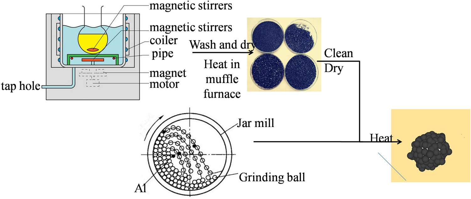
The preparation process of C@Al–EG composites.
Electrochemical experiments were carried out by using CR2025 coin-type cells. The working electrodes contained 84 wt% active materials, 10 wt% carbon black and 6 wt% polyvinylidene fluoride. The electrolyte was 1 M LiPF6 in a solution of 1:1 volume ratio of ethylene carbonate and diethyl carbonate. Celgard 2300 film was used as the separator, and pure lithium metal foil was used as the counter electrode. The coin cells were assembled in an argon-filled glove box (H2O < 0.1 ppm and O2 < 0.1 ppm).
The microstructure and morphology of the composites were analyzed by scanning electron microscopy (SEM; JSM-6700F; JEOL), transmission electron microscopy (TEM; Tecnai G2 F30, FEI), X-ray diffraction (XRD; X’Pert PRO MPD, PANalytical, λ = 0.154 nm) and Raman spectroscopy (514 nm, LabRAM HR800; Horiba Jobin Yvon), and electrochemical measurements were carried out by using a CHI 650D electrochemical workstation (Shanghai Chenhua Co., Ltd, China) with a coin cell at the scan rate of 0.1 mV/s. Galvanostatic charge–discharge measurements were conducted in the voltage range of 0.01 to 3 V with a multichannel battery analyzer (BTS-5V10 mA; Shenzhen Neware Technology Co., Ltd, China) at room temperature.
3 Results and discussion
Figure 2 shows the SEM images and corresponding energy dispersive X-ray analyzer (EDX) elemental analysis of C@Al–EG composites. Figure 2(a)–(e) are the SEM images of the C@Al–EG composites with different aluminum contents. As can be seen from these pictures, C@Al–EG composites exhibit a higher transparency than pure EG. It can be seen that the spherical aluminum nanoparticles are embedded into the EG layers. This may be due to the prolonged sonication, the reduction of the EG lamella and the coating of a few layers of graphene sheets. With the changing contents of Al nanoparticles, the embedding effect is different. The embedding effect gradually improves with the increase in Al nanoparticle contents, but is not very good when the content of Al nanoparticles is about 50%. The possible reason is that large amounts of Al nanoparticles are easily oxidized under high temperature conditions with the increase in Al nanoparticle contents, which affect their electrochemical properties. From the EDX measurements shown in Figure 2(f), we can see that the elements C, O, S and Al exist and it can be further proved that Al metal nanoparticles were successfully embedded in the graphite layers, with an obvious embedded effect. Sulfur existed due to the presence of concentrated sulfuric acid in the process of preparing EG, oxygen was mainly from the slight oxidation of aluminum to produce a small amount of Al2O3 during the preparation process, and the presence of carbon shows that carbon has been successfully encapsulated on the outer surface of Al metal nanoparticles, which mainly comes from the thermal decomposition of ferrocene.
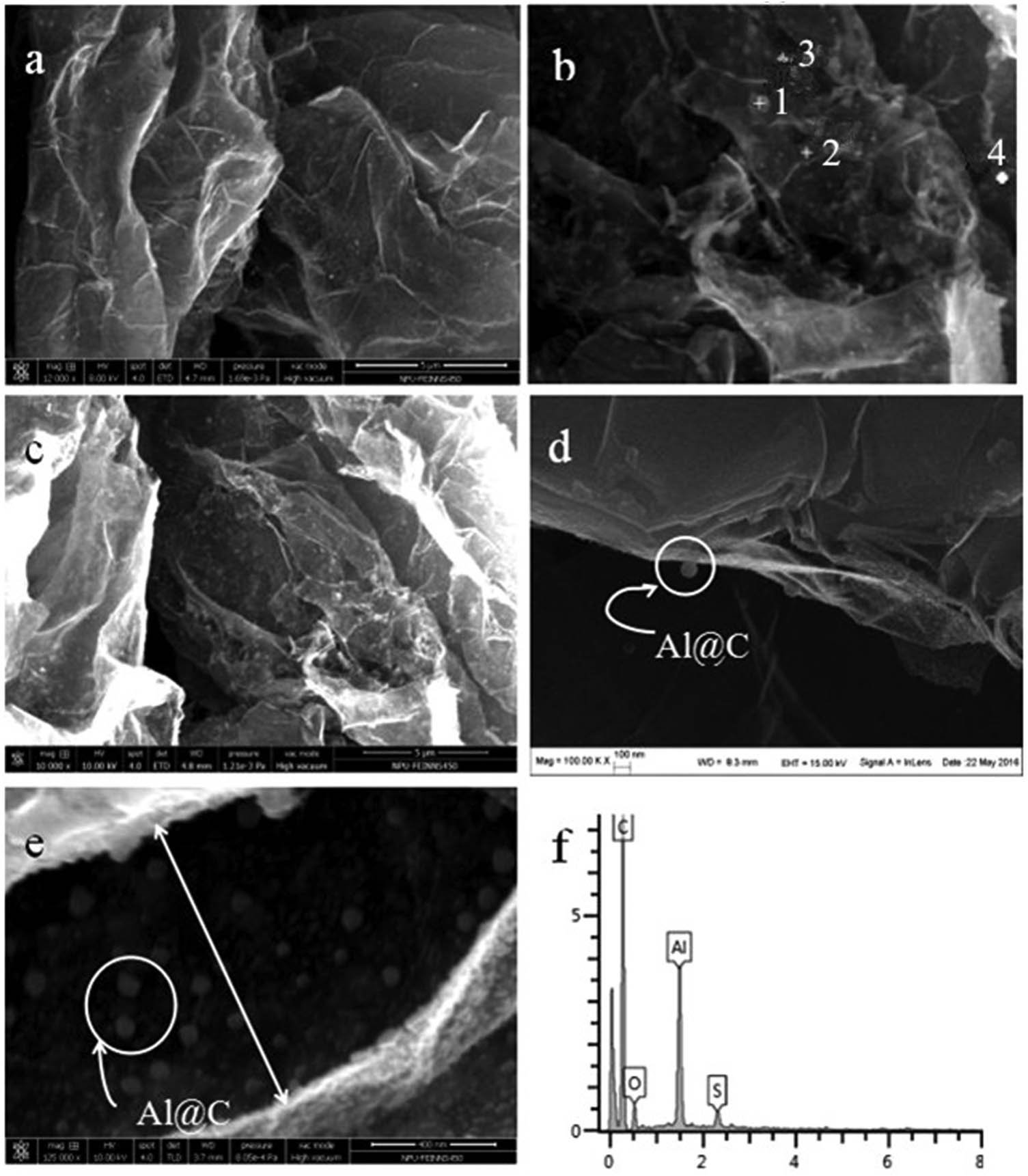
SEM images and corresponding EDX elemental analysis of C@Al–EG composites.
Figure 3 shows the TEM images of C@Al–EG composites with an Al content of 30%. Figure 3(b) on the bottom right shows the selected area electron diffraction pattern. The EG sheet structure is clearly shown in Figure 3(a), and the sheet is small because of the ultrasonic treatment. The inter-slice distribution of black spots indicates the carbon-coated Al nanoparticles, which confirms that the carbon-coated Al nanoparticles have been successfully embedded in EG. The average spacing of Al nanoparticles embedded in the EG (002) crystal face is about 0.5 nm as shown in Figure 3(b), which is significantly larger than that of graphite and EG. The selected area electron diffraction pattern of C@Al–EG composites is a characteristic polycrystalline spectrum, in which the dotted shape indicates the hexagonal crystal structure of the graphite material, and the presence of the ring means that the aluminum metal is successfully embedded in the layers of EG.
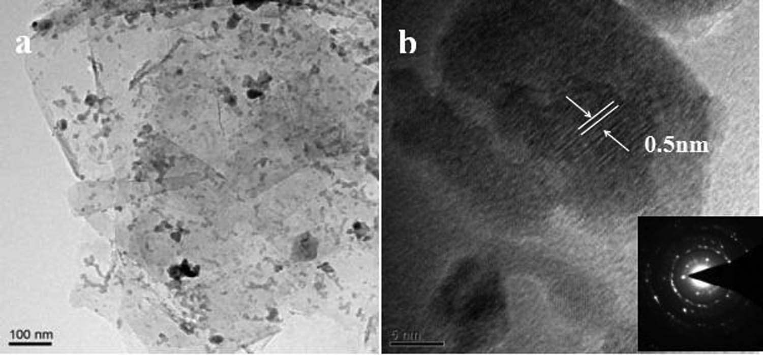
High-resolution transmission electron microscopy images of C@Al–EG composites.
Figure 4 shows the XRD patterns of C@Al–EG composites prepared with different Al contents. The characteristic diffraction peaks of EG were at 2θ = 26.5° and 54.5° corresponding to the (002) and (004) planes. The characteristic diffraction peaks of Al were at 2θ = 38.5°, 65.1° and 82.4° corresponding to the (111), (220) and (311) planes. From the XRD patterns, it can be seen that the XRD spectrum does not change much with the increase in contents of Al. However, when the Al content is 30%, the characteristic diffraction peaks of Al are much sharper and stronger than when the content is 20% and 50%. The reason may be that 20% Al content is inherently low, causing a lower intensity, while 50% Al content has a large amount of Al, and part of the Al may be slightly oxidized into Al2O3 during the preparation process, which causes the corresponding characteristic peak intensity decrease. The characteristic peaks of Al2O3 are not shown because the content is too low. Therefore, 30% of the Al content is the best embedded amount.
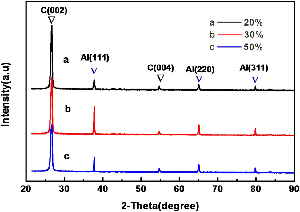
XRD patterns of C@Al–EG composites prepared with different Al contents.
Figure 5 shows the alternating current (AC) impedance of C@Al–EG composites with different Al contents. The AC impedance spectra are composed of the oblique portion in the low frequency region and the semicircular portion in the high frequency region. The oblique portion in the low frequency region is at the top right of the figure, while the semicircle portion in the high frequency region is located at the below left of the figure. The oblique portion is related to the diffusion of lithium ions in the electrode material, and the semicircle portion is related to the electrode interface and the charge transfer impedance. The smaller the radius of the semicircle in the high frequency region, the smaller the charge transfer impedance; the higher the electron conductivity, the better the corresponding electrochemical performance. It can be seen clearly that the C@Al–EG composites have the smallest radius of semicircle in the high frequency region when the Al content is 30%, indicating that the charge transferring impedance is the smallest.
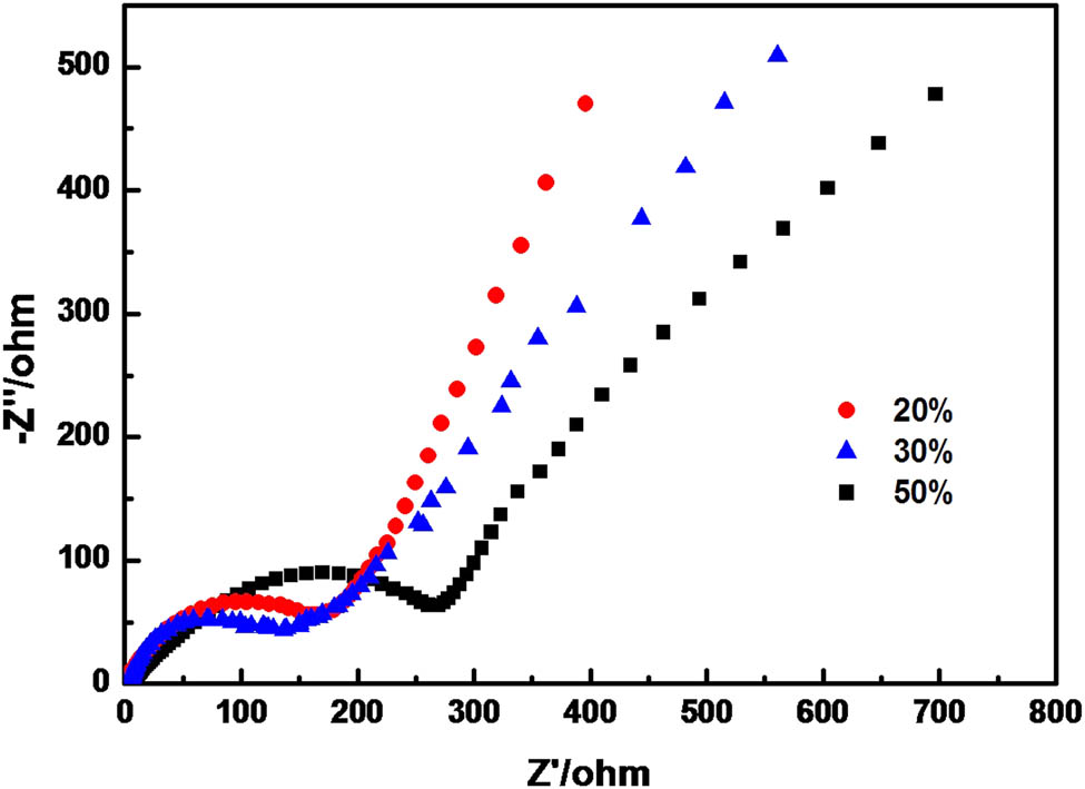
Electrochemical impedance spectra of C@Al–EG composites with different Al contents after 100 cycles.
Figure 6 shows the cyclic voltammetrys (CVs) of C@Al–EG composites containing 30% Al nanoparticles. The negative direction indicates the lithiation process (reduction) and the positive direction indicates the delithiation process (oxidation). In the first cycle, the reduction peak at 0.8 V corresponds to the formation of the solid electrolyte interface (SEI) film, which disappears during the second cycle, indicating that the SEI film is formed only during the first charge and discharge. The reduction peak at about 0.1 V corresponds to the delithiation process getting into the intercalated graphite layers. The obvious oxidation peak at 0.5 V corresponds to the formation process of the Li–Al alloy, and the oxidation peak at 0.2 V represents the dissociation of lithium ions from the intercalated graphite sheets, which is in good agreement with the charge–discharge curves of C@Al–EG composites.

CVs of C@Al–EG composites containing 30% Al nanoparticles.
Figure 7 shows the charge–discharge curves of C@Al–EG composites as electrodes with different Al contents. When the content of Al is 30%, the first discharge capacity reaches 740 mA h/g and the charge capacity reaches 401 mA h/g. When the content of Al is 20%, the first charge and discharge capacities reach 349 and 676 mA h/g, respectively, and the first charge and discharge capacities are 309 and 649 mA h/g, respectively, when the content of Al is 50%. In the charge curves of the three samples, a flat and wide voltage platform appears at 0.5 V, where the Li x Al alloy is formed. For comparison, 30% C@Al–EG composites have the widest voltage platform, which indicates that the alloying has completed. So the charge and discharge capacities are the best when the content of Al is 30%, which are consistent with XRD and SEM results.

Charge–discharge curves of C@Al–EG composites as electrodes with different Al contents.
Figure 8 shows a comparison of the initial charge–discharge curves and the coulombic efficiency between C@Al–EG composites (the Al content of 30%) and EG. As can be seen from the image, the reversible capacity of C@Al–EG composites is significantly higher than that of EG. The initial charge and discharge capacities of the C@Al–EG composites were 401 and 740 mA h/g, respectively, and the coulombic efficiency was 54.2%, while the initial charge and discharge capacities of EG were 295 and 577 mA h/g, respectively, and the coulombic efficiency was just 51.1%. The reversible capacities are largely determined by the unique three-dimensional network structure of C@Al–EG composites, in which Al nanoparticles are coated by pyrolytic carbon and it should be well protected from oxidation at high temperatures or reaction with the electrolysis liquid, leading to more Al nanoparticles in an active state. Meanwhile, the buffering of volume change caused by the embedding improves the reversible capacity and cycle performance greatly.
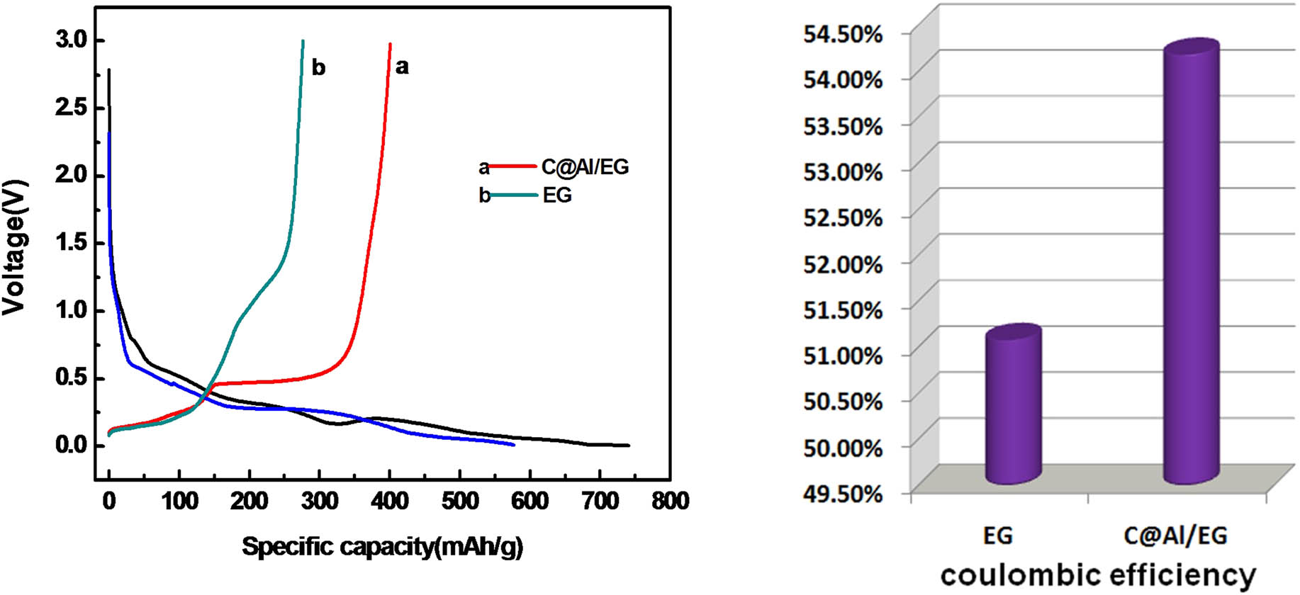
The initial charge–discharge curves and the coulombic efficiency of EG and C@Al–EG composites.
The initial charge curve of C@Al–EG composites can be divided into three stages: the slope at 0–0.5 V corresponds to the intercalation process of lithium ions among graphite sheets, micropores and defects, the flat and wide voltage platform at 0.5 V corresponds to the Li–Al alloy and dealloying process, and the curve at 0.5 V and higher voltage corresponds to the Faraday capacitor, which is at the graphite layer surface or edge. In the first discharge curve of the C@Al–EG composites, an oblique voltage plate at about 0.8 V corresponds to the SEI film [15,16,17] formed on the surface of the electrode material, which reduces the coulombic efficiency and the reversible capacity of the first charge and discharge.
Figure 9 shows the cycling performance of the C@Al–EG composite electrode at the current density of 100 mA/g. The initial coulombic efficiency of the C@Al–EG composites was 54.2%. It can be deduced that the first coulomb efficiency of C@Al–EG composites is directly related to the structure of the EG. C@Al–EG composites and EG have many functional groups, micropores and defects compared with the natural flake graphite, which consumes large amounts of lithium ions during the first cycle, making it dead lithium. Therefore, the low Coulomb efficiency and the irreversible capacity of the first cycle are mainly due to the reaction between lithium ions and functional groups and the SEI membranes formed at the micropores or defects.
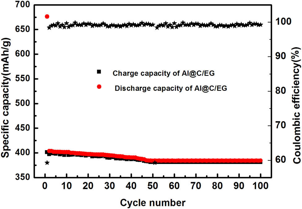
The cycling performance and coulombic efficiencies of C@Al–EG composites
The initial reversible specific capacity of the C@Al–EG composite electrode material is 401 mA h/g, and the capacity decay is very slow, and after 100 cycles the specific capacity remains at 381 mA h/g with the retention rate of up to 95%. C@Al–EG composite electrode materials have such excellent cycling stability due to their unique microstructure. On one hand, C@Al/EG composites have more porous structure because of the intercalation and deintercalation process, which can provide more lithium storage space and improve the capacity of the graphite electrode during the charging and discharging processes for LIBs. In addition, the increase in the interlayer spacing of the graphite can reduce the resistance of Li ion’s deintercalation and damage the graphite’s layered structure, thereby improving the cycle performance. On the other hand, the three-dimensional network structure of C@Al–EG composites can buffer the lithium-induced volumetric effect and protect the Al from reacting with the electrolysis liquid. The carbon-coated structure also releases the agglomeration caused by the nano-effect, so that more aluminum can be alloyed and dealloyed, forming a reversible process, thereby improving the reversible specific capacity and cycle performance.
Figure 10 shows the charge–discharge performance of the C@Al–EG composite electrode at different current densities. The charge–discharge capacity of the C@Al–EG composites was measured after 10 cycles at the current densities of 100, 200, 500 and 1,000 mA/g. The reversible capacities were 399, 371, 319 and 216 mA h/g, respectively. Then, the current density returned to 100 mA/g and the reversible capacity was 369 mA h/g. The reversibility is good, and the capacity retention of the electrode is about 92%. C@Al–EG composite electrodes show a good charge–discharge performance, which is mainly because the carbon-coated aluminum particles can isolate aluminum from the electrolyte to get rid of the chemical reaction. Meanwhile, it will improve the uniformity of this composite system and the high current charge and discharge performance of the C@Al–EG composites.
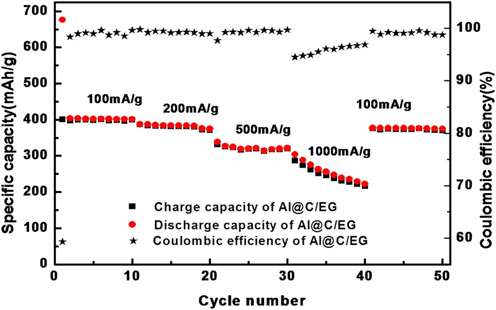
The charge–discharge performance of the C@Al–EG composite electrode.
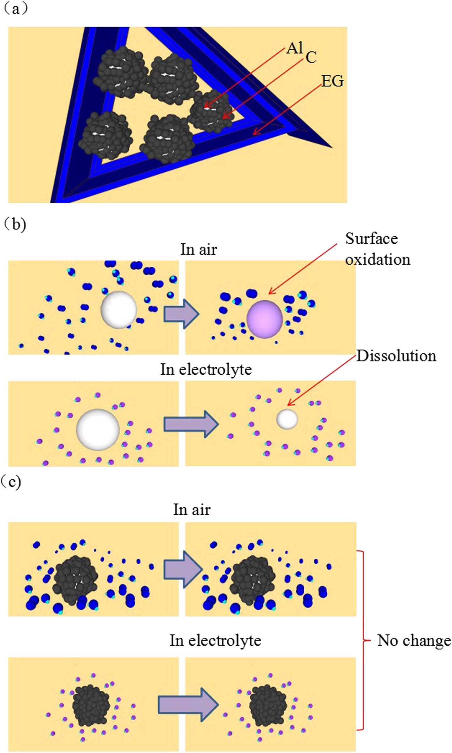
Schematic diagram of C@Al–EG composites and the slow dissolution of aluminum particles in air and electrolyte: (a) schematic diagram if C@Al/EG composites, (b) without coating, (c) with carbon coating.
The C@Al–EG composite has high reversible specific capacity and good cycle stability, in combination with its intercalation and deintercalation mechanisms (Figure 11). The possible reasons are as follows: (1) C@Al–EG composites still retain the EG structure, and the interlayer spacing is increased obviously because of the intercalation of carbon-coated aluminum, which is more favorable for the transport of lithium ions between the graphite layers. Meanwhile, it facilitates the electrochemical adsorption of lithium ions among the interlayer and provides more active sites for lithium ion intercalation, thus increasing the reversible capacity. (2) During the synthesis process of C@Al–EG composites, the graphite layers are reduced, which is similar to the stacking of graphene. The stacking of disordered graphene sheets can greatly improve the transport efficiency of Li ions and the electron conductivity of the electrode materials. Meanwhile, the graphene layer is very curled and pleated, which provides more active lithium insertion sites for C@Al–EG composites. (3) The special structure of carbon-coated aluminum can improve the conductivity and chemical stability. Carbon-coated aluminum could modify the surface chemistry of aluminum and prevent aluminum oxidation at high temperature as well as the reaction with the electrolysis liquid. At the same time, it can promote the conductivity of ions and electrons and inhibit the metal material phase transition and improve the structural stability of aluminum. Therefore, the volume buffering effect caused by the alloying and dealloying processes of lithium could enhance the stability of the cycle performance. C@Al–EG composites have a special embedded metal network structure. In fact, carbon-coated aluminum is embedded in the intercalation layer of EG to form a three-dimensional network structure. The electronic conductivity is improved, the charge transfer impedance is reduced, and the electrochemical performance is also enhanced.
4 Conclusion
In this paper, C@Al–EG composites were obtained by the in situ synthesis technology using EG and metallic aluminum as raw materials. The best doping ratio was 30%. The composites were used as anode materials for LIBs because of their high capacity, excellent cycle stability and rate performance. At a current density of 100 mA h/g, the first reversible capacity of the composites was 401 mA h/g and the decreasing rate of capacity was very slow. The specific capacity remained at 381 mA h/g after 50 cycles, and the retention rate was up to 95%. Even after 10 cycles at a high current density of 1,000 mA/g, the specific capacity remained at 216 mA h/g, and showed excellent cycle stability. The intercalation and deintercalation mechanisms of the C@Al–EG composites were analyzed. The intercalation of EG further increased the interlayer spacing by the amorphous carbon-coated aluminum metal nanoparticles, forming a unique metal network-like structure, which not only provided more lattice intercalation sites but also played a vital role in the buffering of volume change during the process of insertion/extraction of Li+, improving the specific capacity and cycle stability of LIBs greatly.
-
Conflict of interest: The authors declare no conflict of interest regarding the publication of this paper.
Acknowledgments
This work was supported by the Natural Science Foundation of China (51672221 and 51872231), the Key Industrial Chain Project of Shaanxi Province (2018ZDCXL-GY-08-07), the Fundamental Research Funds for the Central Universities and National College Students Innovation and Entrepreneurship Training Program (201810699094).
References
[1] Poizot P, Laruelle S, Grugeon S, Dupont L, Tarascon JM. Nano-sized transition-metal oxides as negative-electrode materials for lithium-ion batteries. ChemInform. 2001;32(3):496–9.10.1002/chin.200103013Search in Google Scholar
[2] Yoo EJ, Kim J, Hosono E, Zhou H, Kudo T, Honma I. Large reversible Li storage of graphene nanosheet families for use in rechargeable lithium ion batteries. Nano Lett. 2008;8(8):2277–82.10.1021/nl800957bSearch in Google Scholar PubMed
[3] Huggins RA. Lithium alloy negative electrodes formed from convertible oxides. Solid State Ionics. 1998;113–115(6):57–67.10.1016/S0167-2738(98)00275-6Search in Google Scholar
[4] Li H, Guo X, Wang W. Forming performance of an as-quenched novel aluminum–lithium alloy. Int J Adv Des Manuf Technol. 2015;78(1):659–66.10.1007/s00170-014-6677-7Search in Google Scholar
[5] Nithyadharseni P, Reddy MV, Nalini B, Kalpana M, Chowdari BVR. Sn-based intermetallic alloy anode materials for the application of lithium ion batteries. Electrochim Acta. 2015;161:261–8.10.1016/j.electacta.2015.02.057Search in Google Scholar
[6] Matsunoshita H, Edalati K, Furui M. Ultrafine-grained magnesium–lithium alloy processed by high-pressure torsion: low-temperature superplasticity and potential for hydroforming. Mater Sci Eng A. 2015;640:443–8.10.1016/j.msea.2015.05.103Search in Google Scholar
[7] Wu R, Yan Y, Wang G, Murr LE, Han W, Zhang Z, et al. Recent progress in magnesium–lithium alloys. Int Mater Rev. 2015;60(2):65–100.10.1179/1743280414Y.0000000044Search in Google Scholar
[8] Noh M, Cho J, Kwon Y, Lee H, Kim Y, Kim MG. Effect of amorphous carbon coating on tin anode metal particles. Electrochem Soc. 2006.10.1149/MA2005-01/3/161Search in Google Scholar
[9] Arie AA, Lee JK. Electrochemical characteristics of lithium metal anodes with diamond like carbon film coating layer. Diamond Relat Mater. 2011;20(3):403–8.10.1016/j.diamond.2011.01.040Search in Google Scholar
[10] Fang G, Kaneko S, Liu W, Xia B, Sun H, Zheng H, et al. Persistent cyclestability of carbon coated Zn–Sn metal oxide/carbon microspheres as highly reversible anode material for lithium-ion batteries. Electrochim Acta. 2013;111(6):627–34.10.1016/j.electacta.2013.08.096Search in Google Scholar
[11] Zhang R, Fang G, Liu W, Xia B, Sun H, Zheng H, et al. Preparation and electrochemical properties of core–shell carbon coated Mn–Sn complex metal oxide as anode materials for lithium-ion batteries. Appl Surf Sci. 2014;292(3):682–7.10.1016/j.apsusc.2013.12.033Search in Google Scholar
[12] Alrashdan A, Mayyas AT, Al-Hallaj S. Thermo-mechanical behaviors of the expanded graphite-phase change material matrix used for thermal management of Li-ion battery packs. J Mater Process Technol. 2010;210(1):174–9.10.1016/j.jmatprotec.2009.07.011Search in Google Scholar
[13] Zhao T, She S, Ji X, Guo X, Jin W, Zhu R, et al. Expanded graphite embedded with aluminum nanoparticles as superior thermal conductivity anodes for high-performance lithium-ion batteries. Sci Rep. 2016;6:33833.10.1038/srep33833Search in Google Scholar PubMed PubMed Central
[14] Wen Y, He K, Zhu Y, Han F, Xu Y, Matsuda I, et al. Expanded graphite as superior anode for sodium-ion batteries. Nat Commun. 2014;5:4033–4033.10.1038/ncomms5033Search in Google Scholar PubMed
[15] Huff LA, Tavassol H, Esbenshade JL, Xing W, Chiang YM, Gewirth AA, et al. Identification of Li-ion battery SEI compounds through (7)Li and (13)C solid-state MAS NMR spectroscopy and MALDI-TOF mass spectrometry. ACS Appl Mater Interfaces. 2016;8(1):371.10.1021/acsami.5b08902Search in Google Scholar PubMed
[16] Xu MQ, Li WS, Zuo XX, Liu JS, Xu X. Performance improvement of lithium ion battery using PC as a solvent component and BS as an SEI forming additive. J Power Sources. 2007;174(2):705–10.10.1016/j.jpowsour.2007.06.112Search in Google Scholar
[17] Kim SP, Duin ACTV, Shenoy VB. Effect of electrolytes on the structure and evolution of the solid electrolyte interphase (SEI) in Li-ion batteries: a molecular dynamics study. J Power Sources. 2011;196(20):8590–8597.10.1016/j.jpowsour.2011.05.061Search in Google Scholar
© 2020 Xin Zhao et al., published by De Gruyter
This work is licensed under the Creative Commons Attribution 4.0 International License.
Articles in the same Issue
- Research Articles
- Generalized locally-exact homogenization theory for evaluation of electric conductivity and resistance of multiphase materials
- Enhancing ultra-early strength of sulphoaluminate cement-based materials by incorporating graphene oxide
- Characterization of mechanical properties of epoxy/nanohybrid composites by nanoindentation
- Graphene and CNT impact on heat transfer response of nanocomposite cylinders
- A facile and simple approach to synthesis and characterization of methacrylated graphene oxide nanostructured polyaniline nanocomposites
- Ultrasmall Fe3O4 nanoparticles induce S-phase arrest and inhibit cancer cells proliferation
- Effect of aging on properties and nanoscale precipitates of Cu-Ag-Cr alloy
- Effect of nano-strengthening on the properties and microstructure of recycled concrete
- Stabilizing effect of methylcellulose on the dispersion of multi-walled carbon nanotubes in cementitious composites
- Preparation and electromagnetic properties characterization of reduced graphene oxide/strontium hexaferrite nanocomposites
- Interfacial characteristics of a carbon nanotube-polyimide nanocomposite by molecular dynamics simulation
- Preparation and properties of 3D interconnected CNTs/Cu composites
- On factors affecting surface free energy of carbon black for reinforcing rubber
- Nano-silica modified phenolic resin film: manufacturing and properties
- Experimental study on photocatalytic degradation efficiency of mixed crystal nano-TiO2 concrete
- Halloysite nanotubes in polymer science: purification, characterization, modification and applications
- Cellulose hydrogel skeleton by extrusion 3D printing of solution
- Crack closure and flexural tensile capacity with SMA fibers randomly embedded on tensile side of mortar beams
- An experimental study on one-step and two-step foaming of natural rubber/silica nanocomposites
- Utilization of red mud for producing a high strength binder by composition optimization and nano strengthening
- One-pot synthesis of nano titanium dioxide in supercritical water
- Printability of photo-sensitive nanocomposites using two-photon polymerization
- In situ synthesis of expanded graphite embedded with amorphous carbon-coated aluminum particles as anode materials for lithium-ion batteries
- Effect of nano and micro conductive materials on conductive properties of carbon fiber reinforced concrete
- Tribological performance of nano-diamond composites-dispersed lubricants on commercial cylinder liner mating with CrN piston ring
- Supramolecular ionic polymer/carbon nanotube composite hydrogels with enhanced electromechanical performance
- Genetic mechanisms of deep-water massive sandstones in continental lake basins and their significance in micro–nano reservoir storage systems: A case study of the Yanchang formation in the Ordos Basin
- Effects of nanoparticles on engineering performance of cementitious composites reinforced with PVA fibers
- Band gap manipulation of viscoelastic functionally graded phononic crystal
- Pyrolysis kinetics and mechanical properties of poly(lactic acid)/bamboo particle biocomposites: Effect of particle size distribution
- Manipulating conductive network formation via 3D T-ZnO: A facile approach for a CNT-reinforced nanocomposite
- Microstructure and mechanical properties of WC–Ni multiphase ceramic materials with NiCl2·6H2O as a binder
- Effect of ball milling process on the photocatalytic performance of CdS/TiO2 composite
- Berberine/Ag nanoparticle embedded biomimetic calcium phosphate scaffolds for enhancing antibacterial function
- Effect of annealing heat treatment on microstructure and mechanical properties of nonequiatomic CoCrFeNiMo medium-entropy alloys prepared by hot isostatic pressing
- Corrosion behaviour of multilayer CrN coatings deposited by hybrid HIPIMS after oxidation treatment
- Surface hydrophobicity and oleophilicity of hierarchical metal structures fabricated using ink-based selective laser melting of micro/nanoparticles
- Research on bond–slip performance between pultruded glass fiber-reinforced polymer tube and nano-CaCO3 concrete
- Antibacterial polymer nanofiber-coated and high elastin protein-expressing BMSCs incorporated polypropylene mesh for accelerating healing of female pelvic floor dysfunction
- Effects of Ag contents on the microstructure and SERS performance of self-grown Ag nanoparticles/Mo–Ag alloy films
- A highly sensitive biosensor based on methacrylated graphene oxide-grafted polyaniline for ascorbic acid determination
- Arrangement structure of carbon nanofiber with excellent spectral radiation characteristics
- Effect of different particle sizes of nano-SiO2 on the properties and microstructure of cement paste
- Superior Fe x N electrocatalyst derived from 1,1′-diacetylferrocene for oxygen reduction reaction in alkaline and acidic media
- Facile growth of aluminum oxide thin film by chemical liquid deposition and its application in devices
- Liquid crystallinity and thermal properties of polyhedral oligomeric silsesquioxane/side-chain azobenzene hybrid copolymer
- Laboratory experiment on the nano-TiO2 photocatalytic degradation effect of road surface oil pollution
- Binary carbon-based additives in LiFePO4 cathode with favorable lithium storage
- Conversion of sub-µm calcium carbonate (calcite) particles to hollow hydroxyapatite agglomerates in K2HPO4 solutions
- Exact solutions of bending deflection for single-walled BNNTs based on the classical Euler–Bernoulli beam theory
- Effects of substrate properties and sputtering methods on self-formation of Ag particles on the Ag–Mo(Zr) alloy films
- Enhancing carbonation and chloride resistance of autoclaved concrete by incorporating nano-CaCO3
- Effect of SiO2 aerogels loading on photocatalytic degradation of nitrobenzene using composites with tetrapod-like ZnO
- Radiation-modified wool for adsorption of redox metals and potentially for nanoparticles
- Hydration activity, crystal structural, and electronic properties studies of Ba-doped dicalcium silicate
- Microstructure and mechanical properties of brazing joint of silver-based composite filler metal
- Polymer nanocomposite sunlight spectrum down-converters made by open-air PLD
- Cryogenic milling and formation of nanostructured machined surface of AISI 4340
- Braided composite stent for peripheral vascular applications
- Effect of cinnamon essential oil on morphological, flammability and thermal properties of nanocellulose fibre–reinforced starch biopolymer composites
- Study on influencing factors of photocatalytic performance of CdS/TiO2 nanocomposite concrete
- Improving flexural and dielectric properties of carbon fiber epoxy composite laminates reinforced with carbon nanotubes interlayer using electrospray deposition
- Scalable fabrication of carbon materials based silicon rubber for highly stretchable e-textile sensor
- Degradation modeling of poly-l-lactide acid (PLLA) bioresorbable vascular scaffold within a coronary artery
- Combining Zn0.76Co0.24S with S-doped graphene as high-performance anode materials for lithium- and sodium-ion batteries
- Synthesis of functionalized carbon nanotubes for fluorescent biosensors
- Effect of nano-silica slurry on engineering, X-ray, and γ-ray attenuation characteristics of steel slag high-strength heavyweight concrete
- Incorporation of redox-active polyimide binder into LiFePO4 cathode for high-rate electrochemical energy storage
- Microstructural evolution and properties of Cu–20 wt% Ag alloy wire by multi-pass continuous drawing
- Transparent ultraviolet-shielding composite films made from dispersing pristine zinc oxide nanoparticles in low-density polyethylene
- Microfluidic-assisted synthesis and modelling of monodispersed magnetic nanocomposites for biomedical applications
- Preparation and piezoresistivity of carbon nanotube-coated sand reinforced cement mortar
- Vibrational analysis of an irregular single-walled carbon nanotube incorporating initial stress effects
- Study of the material engineering properties of high-density poly(ethylene)/perlite nanocomposite materials
- Single pulse laser removal of indium tin oxide film on glass and polyethylene terephthalate by nanosecond and femtosecond laser
- Mechanical reinforcement with enhanced electrical and heat conduction of epoxy resin by polyaniline and graphene nanoplatelets
- High-efficiency method for recycling lithium from spent LiFePO4 cathode
- Degradable tough chitosan dressing for skin wound recovery
- Static and dynamic analyses of auxetic hybrid FRC/CNTRC laminated plates
- Review articles
- Carbon nanomaterials enhanced cement-based composites: advances and challenges
- Review on the research progress of cement-based and geopolymer materials modified by graphene and graphene oxide
- Review on modeling and application of chemical mechanical polishing
- Research on the interface properties and strengthening–toughening mechanism of nanocarbon-toughened ceramic matrix composites
- Advances in modelling and analysis of nano structures: a review
- Mechanical properties of nanomaterials: A review
- New generation of oxide-based nanoparticles for the applications in early cancer detection and diagnostics
- A review on the properties, reinforcing effects, and commercialization of nanomaterials for cement-based materials
- Recent development and applications of nanomaterials for cancer immunotherapy
- Advances in biomaterials for adipose tissue reconstruction in plastic surgery
- Advances of graphene- and graphene oxide-modified cementitious materials
- Theories for triboelectric nanogenerators: A comprehensive review
- Nanotechnology of diamondoids for the fabrication of nanostructured systems
- Material advancement in technological development for the 5G wireless communications
- Nanoengineering in biomedicine: Current development and future perspectives
- Recent advances in ocean wave energy harvesting by triboelectric nanogenerator: An overview
- Application of nanoscale zero-valent iron in hexavalent chromium-contaminated soil: A review
- Carbon nanotube–reinforced polymer composite for electromagnetic interference application: A review
- Functionalized layered double hydroxide applied to heavy metal ions absorption: A review
- A new classification method of nanotechnology for design integration in biomaterials
- Finite element analysis of natural fibers composites: A review
- Phase change materials for building construction: An overview of nano-/micro-encapsulation
- Recent advance in surface modification for regulating cell adhesion and behaviors
- Hyaluronic acid as a bioactive component for bone tissue regeneration: Fabrication, modification, properties, and biological functions
- Theoretical calculation of a TiO2-based photocatalyst in the field of water splitting: A review
- Two-photon polymerization nanolithography technology for fabrication of stimulus-responsive micro/nano-structures for biomedical applications
- A review of passive methods in microchannel heat sink application through advanced geometric structure and nanofluids: Current advancements and challenges
- Stress effect on 3D culturing of MC3T3-E1 cells on microporous bovine bone slices
- Progress in magnetic Fe3O4 nanomaterials in magnetic resonance imaging
- Synthesis of graphene: Potential carbon precursors and approaches
- A comprehensive review of the influences of nanoparticles as a fuel additive in an internal combustion engine (ICE)
- Advances in layered double hydroxide-based ternary nanocomposites for photocatalysis of contaminants in water
- Analysis of functionally graded carbon nanotube-reinforced composite structures: A review
- Application of nanomaterials in ultra-high performance concrete: A review
- Therapeutic strategies and potential implications of silver nanoparticles in the management of skin cancer
- Advanced nickel nanoparticles technology: From synthesis to applications
- Cobalt magnetic nanoparticles as theranostics: Conceivable or forgettable?
- Progress in construction of bio-inspired physico-antimicrobial surfaces
- From materials to devices using fused deposition modeling: A state-of-art review
- A review for modified Li composite anode: Principle, preparation and challenge
- Naturally or artificially constructed nanocellulose architectures for epoxy composites: A review