An analytical study of wireless power transmission system with metamaterials
-
Uday Kumar Mudhigollam
 und
Mohana Rao Mandava
und
Mohana Rao Mandava


Abstract
Computation of transmission system efficiency of electromagnetic radiation becomes inaccurate when Friis formula is used in Fresnel zone (near-field zone) of wireless power transmission (WPT). A novel methodology has been proposed in this paper for estimation of the power density, received power and transmission system efficiency at a particular operating frequency in the near-field zone. The power transfer and transmission system efficiency need to be maximized for minimal dimensions of transmitter and receiver. Utilization of negative refractive index metamaterials (MM) between transmitter and receiver is proposed to achieve maximum power transfer. In the present paper, variation of received power and system efficiency with respect to transmitting distance is computed and compared for WPT system with and without metamaterials. The variation of system efficiency is studied for varied location of metamaterial from transmitter by assuming metamaterial diameter at a given location is greater than or equal to the beam diameter at that location. Different configurations with varied input power and transmitting distances from shorter to longer range are considered in the study to analyse parameters that affect system efficiency. The approach for identifying optimal number of metamaterials and their placement between transmitter and receiver for maximum power transfer has also been discussed.
1 Introduction
Wireless Power Transmission (WPT) is a promising technique for the long-term power supply of wireless applications. Wireless power transfer via electromagnetic radiation is more efficient than inductive power transfer. WPT system converts available energy into microwave one, deliver this energy to the atmosphere through transmitter and reconvert microwave signal into DC by means of reception antenna. Studies on WPT are divided into design of Magnetron to generate radio frequency (RF) in the order of GHz, transmission antennas, Microwave Transmission, Receiving antennas and RF-DC conversion. One more important component for this type of wireless power transfer is the Rectenna. Rectenna basically consists of Reception Antenna, impedance matching circuits, filter circuits, and load circuits. The amount of power that can be transferred is limited. The transmitted power is limited by regulations and the received power is attenuated, mainly due to free-space path loss. Power transmission efficiencies depend mainly on type of antennas, distance to which power to be transmitted, operating frequency etc.
WPT was first initiated from the concept of Solar Power Satellites, one of the future alternative energy, and studied continuously all over the world. This technology has the advantage of having higher efficiency than solar energy on ground and ensure receipt of infinite energy without effect of weather conditions. WPT can be divided into two categories namely near-field approach and far-field approach. In near-field approach, power is transferred over short distances by magnetic fields or electric fields using inductive coupling or capacitive coupling respectively. In far-field approach, power is transferred over longer distances by electromagnetic radiation like microwaves or laser beams (Kawasaki 2011; Shinohara, Kubo, and Tonomura 2013). The antenna that is predominantly used at microwave frequencies is micro-strip patch based antenna and depending on power rating multiple antennas/sensors in the form of rectangular or square array are used. The power density at any point along the line normal to the transmitter antenna array is determined using simpler approach. However, the power density on receiving antenna array varies from one point to another. The power density depends on dimensions of the receiving antenna array and its distance from the transmitting antenna. If receiving antenna is not properly designed, the amount of power transmitted from transmitting antenna may not be fully used and transmission system efficiency becomes low. The transmitting antenna is considered to be square/rectangular array type and the transmitting antenna area is generally less than receiving antenna (Shinohara 2012).
Currently, microwave power transfer technology is being utilized in many fields like electric vehicles and mobile phones that are powered by electromagnetic waves and the microwave power transfer systems inside buildings (Kawasaki 2011; Shinohara, Kubo, and Tonomura 2013). The microstrip patch antenna array has merits of a simple manufacturing process, small volume, light weight, low profile, and easy integration. Hence, it is commonly used in the field of microwave wireless power transfer. A series of theoretical and experimental results about microwave power transfer systems using the microstrip patch antenna arrays were presented (Shinohara 2012). Several methods have been employed to increase the power transmission system efficiency, performances, and robustness of the microwave power transfer systems by designing transmitting arrays (Franceschetti, Massa, and Rocca 2011; Li and Jandhyala 2012; Manica et al. 2008; Oliveri et al. 2012). A microwave power transfer system which is functioning at the frequency of 5.8 GHz with 8 × 8 transmitting antenna array and 4 × 4 receiving antenna array has been presented, and 33.4 % transmission system efficiency has been claimed at the distance of 40 cm (Gowda et al. 2016). In addition to this, an optimized microwave power transfer system with 8 × 8 transmitting patch antenna array and 8 × 8 receiving patch antenna array at the frequency of 5.8 GHz and the distance of 100 cm has been presented for improving the transmission system efficiency to 46.9 % (Yang, Wen, and Sun 2017).
MMs are widely consisting of artificial structures that show special electromagnetic properties like negative refractive index (Yang, Wen, and Sun 2017). The wavelength is usually much higher than the elemental structures in MMs and the novel electromagnetic properties of MMs are achieved from these elemental structures, rather from composite materials. Parameters like electric permittivity and magnetic permeability can be used to describe the electromagnetic properties of MMs (Smith, Pendry, and Wiltshire 2004). Almost arbitrary parameters can be achieved by carefully designing the elemental structures of MMs. Negative refraction happens at both interfaces of negative refractive index material which means, a negative refractive index material slab recovers propagating waves (Wang, Nishino, and Teo 2010). The transmission system efficiency has been experimentally measured at 2.45 GHz centre frequency by keeping the receiver at 1 m distance from the transmitter. The transmission system efficiency of 26.91 % without meta material has increased to the transmission system efficiency of 32.6 % with MM (Shashank and Nayak 2021).
Friis transmission equation can only be used at far-field distances because it is assumed that the electromagnetic wave is plane wave at far-field. As the electromagnetic wave is spherical wave in the near-field distances, Friis transmission equation cannot be used at near-field zone (Brown and Eves 1992). Four methods namely Standard derivation, Fresnel optics derivation, Gaussian beam derivation and Mode derivation have been proposed to derive Friis transmission equation (Hogg 1993). The transmission efficiency can be theoretically increased to 100 % if the infinite Rectenna array is used to absorb the electromagnetic radiation (Otsuka et al. 1990; Shinohara 2010). A method has been proposed for determining optimal excitation magnitudes and phases to achieve maximum efficiencies in a multiple input single output WPT system (Lee et al. 2020). The experimental results of the transmission properties in Fresnel region have been discussed (Juengkittikul and Promwong 2009). Although few corrections have been made to the Friis transmission equation to consider near field distances (Breinbjerg and Kaslis 2017; Chu 1965; Kim, Xu, and Rahmat-Samii 2013), not significant contribution is available in the literature. Further, transmission efficiency calculations in the near field are not available. Friis transmission formula has been used by several researchers for various applications (Ghobad and de Moraes 2012; Kim et al. 2015; Udomsom et al. 2017). An asymptotic generalization of the Friis formula which can be used for both near-field and far-field regions has been discussed for variety of antennas. An approximate generalization of the Friis formula based on the fundamental mode of Gaussian beams was proposed in (Hogg 1993), but instructions on deriving a generalized gain reduction factor have not been presented. An asymptotic correction has been made to Friis equation to determine the power transmission efficiency between transmitter and receiver in either Fresnel or far-field regions. Though the proposed correction to Friis equation improves the significant accuracy, the paper does not address the transmission efficiency among the antenna arrays (Chu 1965). A mean correction term has been proposed to modify Friis transmission equation for determining the transmission efficiency in the near-field region between the transmitter array and the receiver. However, the generalized approach/methodology for calculating distances between transmitter array sensors and the receiver has not been presented (Kim et al. 2019). Hence there is a need for modifying Friis formula for estimating radiating power density, received power and transmission efficiency in the Fresnel zone. A new and simpler approach has been discussed in this paper for estimating beam efficiency in the Fresnel zone.
In the present paper, it has been discussed about improving overall WPT system efficiency by using MMs at regular distances between transmitter and receiver. An analytical study has been carried out by estimating negative refractive index of MM for the given dimensions to obtain optimal WPT system. Section II presents the design of WPT system with existing Friis formula and proposed alternate approach. Section III presents the design of WPT system by using negative refractive index MMs. Section IV presents the details of various WPT system models considered for study. Section V presents the variation of radiating power density, received power and transmission system efficiency with respect to transmitting distance for different WPT system models with and without MMs. The approach for identifying optimal number of MMs and their placement between transmitter and receiver for maximum power transfer and transmission system efficiency over longer distances has also been discussed. Section VI presents the FEM based analysis of WPT system to validate the analytical results. Section VII presents the conclusions.
2 Design of WPT system
The design of WPT system has been explained in this section using existing Friis formula and proposed alternate approach.
2.1 Friis formula
The ratio of receiving power to transmitted power gives transmission efficiency as per Friis formula given by equation (1). The transmission efficiency is also known as beam efficiency. Friis equation shall be accurate if distance between transmitter and receiver is more than minimum distance (d min) given by equation (2).
where G r is receiving antenna gain, G t is transmitting antenna gain, d is propagation distance between antennas, meters, A r is effective area of receiving antenna, Sq. meters, A t is effective area of transmitting antenna, Sq. meters, P r is radiating power, Watts, P t is transmitting power, Watts
where D is the largest linear dimension of an antenna, meters. λ is wavelength corresponding to operating frequency “f”, meters.
2.2 Proposed alternate approach
The following assumptions are made in order to compare the transmission efficiency estimated through existing Friis equation and proposed Friis equation in the present study:
Side lobes and back lobes are not considered for the computation. It means the entire equivalent power input is considered as main beam.
Absorption of microwaves by the atmosphere is neglected.
The electromagnetic fields from the transmitter array panel are coherently added at the receiver array panel.
The ideal radiation distribution of circular cross section is considered.
The formula for calculating radiating power density (P D ) at any propagation distance ‘d’ is given by the equation (3).
where D
b
is the diameter of beam at distance ‘d’, meters, P
in is the input power, Watts and
If the power density at the propagation distance ‘d’ is to be calculated, the microwave beam diameter D b must be known at that distance.
Assume that the microwave beam has propagated to the distance beyond Fresnel region then the beam angle in degrees (Merrill 2002) is given by the equation (4).
where D is reflector diameter, meters and λ is carrier wavelength, meters
In order to find out the beam diameter at any propagating distance, it is assumed that the beam is divergent from the transmitter itself as shown in Figure 1.

Beam divergence from transmitter.
The beam diameter b
D
at propagation distance
The angle θ can be approximately calculated using the below equation given by (6)
The beam diameter D b at any propagating distance in the Fresnel region (Trichili et al. 2020) can be calculated using the equation given by (7).
If the effective area of receiving antenna is known, the received power on receiver can be calculated by multiplying effective area with power density calculated using equation (3). The received power is given by equation (8).
where D
r
is the receiver diameter, meters and
The formula for WPT system efficiency is given by equation (9).
3 WPT with metamaterials
The law of refraction is as shown in Figure 2. It states that the incoming beam and outgoing beam are parallel to each other. It can also be proved that the incoming beam angle and outgoing beam angle are equal as shown below in equation (10) using Snell’s law.
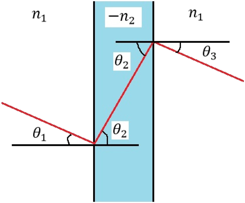
Law of refraction.
When the diverging microwave beam enters into the MM of negative refractive index, it can be ensured that the microwave beam converges within the MM such that it comes out with the same beam diameter equal to the beam diameter at the transmitter. The more the number of MMs are used in between transmitter and receiver, the greater will be the distance the microwave beam travels. It is important to note that the efficiency of MM shall be increased to highest possible level. One must ensure that the dimensions of MM must be greater than the beam diameter at the location of MM to capture all the microwave beam. The more the negative value of the refractive index of the MM the more will be reduction of the beam diameter when it comes out of the MM for given thickness of the MM (refer Figure 3).

Variation in the microwave beam diameter as it encounters MMs.
The receiver size needs to be more compared to the transmitter size when it is ensured that the microwave beam comes out of the MM with same beam diameter as the beam diameter at the transmitter. In order to maintain the receiver and transmitter of the same size, it is necessary to ensure that that the microwave beam diameter must be smaller than that of transmitter reflector diameter. The required microwave beam diameter at the exit of MM depends on design requirements like location of receiver from the last MM, value of negative refractive index MM, thickness of MM etc.
Let t m be the MM thickness, D 1 be the beam diameter when entering the MM and D 2 be the beam diameter when leaving the MM. Then refractive index n 2 of the MM is derived and presented in equation (11).
The above equation can be modified and rewritten to get the required beam diameter when leaving the MM in terms of parameters like material thickness, refractive index of the MM etc., as given in equation (12).
It is evident from equation (12) that for given reflector diameter, frequency of operation and material thickness, the beam diameter while leaving the MM decreases as the negative refractive index increases.
4 Modeling details and technical parameters
The MATLAB software based program is developed in the study to optimize the design parameters of the WPT system. The software program developed in the study calculates performance parameters of WPT like radiating power density, received power, beam diameter etc. The novelty of program is that it can calculate these performance parameters in the near-filed zone by calculating power density using an alternate approach instead of applying existing Friis formula which is not valid for near-field zone. The program takes the parameters like transmitter reflector diameter, receiver reflector diameter, operating frequency, transmitter efficiency, distance between MMs, MM thickness, MM efficiency, distance between last MM and receiver, number of MMs and transmit power as input parameters. Table 1 shows the input parameters for various WPT models considered for study.
Input parameters for WPT Models considered for study.
| S. no. | Input parameters | Model I | Model II | Model III | Model IV |
|---|---|---|---|---|---|
| 1 | Transmitter reflector diameter, m | 0.27 | 1 | 12 | 20 |
| 2 | Receiver reflector diameter, m | 0.27 | 1.8, 1.836, 1.872 | 7, 12, 17 | 20 |
| 3 | Centre frequency, GHz | 2.45 | 2.45 | 2.45 | 2.45 |
| 4 | Reflector efficiency, % | 70 | 70 | 70 | 70 |
| 5 | Distance between MMs, m | – | 20 | 800, 1600 | 2400 |
| 6 | MM thickness, m | 0.01 | 0.01 | 0.01 | 0.01 |
| 7 | MM efficiency, % | 80–90 | 80–90 | 80–90 | 80–90 |
| 8 | MM diameter, m | 0.23–0.33 | 2–2.4 | 12.5–16 | 21–26 |
| 9 | Number of MMs | 1 | 2 | 3 | 3 |
| 10 | Input power, kW | 0.5 | 2 | 15 | 15 |
| 11 | Distance between transmitter and receiver, m | 1 | 60 | 2800 | 8400 |
Different diameters of transmitter and receiver are considered to estimate the WPT system efficiency. Generally, in small scale commercial WPT models, transmitter and receiver diameters are of the same. In the present study, slightly higher and lower diameters of receiver over transmitter have been considered to analyze the effect on WPT system efficiency. Smaller reflector diameter of 0.27 m is assumed to verify the experimental data considered for the study. Various reflector diameters are considered to estimate WPT system efficiency at different distances of receiver from the transmitter. Further, increased reflector diameter is required to transmit power for longer distances. In other words, to receive power with increased efficiencies at longer distances in the order of kilometers, higher diameters of reflector and MM are required. Further effect of multiple numbers of MM with increased distance between transmitter and receiver is also analyzed. The MM diameter is considered to be in the same order of transmitter and reflector diameter. As MM diameter has significant effect on radiating power density, effect of fine variation in MM diameter has been analyzed in the study. Table 2 shows the output parameters for various WPT models considered for study. The developed MATLAB program calculates the parameters like beam diameter at a particular location from the transmitter, refractive index of MM, power density at a particular distance from the transmitter, received power by the receiver etc. as output parameters. The developed numerical program calculates the beam diameter, power density and received power at different distances from the transmitter with and without considering MMs. The present analysis also aims to calculate the WPT system efficiency for different configurations and compare for different diameters of transmitter, receiver and MMs.
Output parameters for WPT models considered in the study.
| S. no. | Output parameters |
|---|---|
| 1 | WPT system efficiency, % |
| 2 | Radiating power density at various distances, W/m2 |
| 3 | Receiving power at receiver, W |
| 4 | Radiating power density at receiver, W/m2 |
5 Results and discussion
WPT Model I consisting of transmitter, receiver and MM is as shown in Figure 4. The WPT system efficiency curve obtained experimentally (Shashank and Nayak 2021) has been considered to validate the proposed model (Model-I). The measured efficiency increases from 30.2 % to 32.6 % from 0 m to 0.3 m distance from transmitter (refer Figure 5). Model-I has been considered to validate the proposed computational program results with the above reported efficiency measurements. The transmitter and receiver reflector diameter of 0.27 m each and the MM diameter of 0.29 m are considered for the analysis. The transmitter reflector efficiency is considered to be 70 % while the MM efficiencies are considered to be in the range of 80–90 %. The WPT system efficiency is defined as the ratio of received power to the input power. The transmission system efficiency has been plotted for varied location of MM between the transmitter and receiver and shown in Figure 6. The receiver is considered to be at 1 m distance from the transmitter for the analysis. It is clear from the results that the WPT system efficiency is 27.23 % without MM. Further, the system efficiency increases and reaches the highest level (33.31 %) for the MM of 80 % efficiency located at around 0.5 m from transmitter. The WPT system efficiency decreases as MM moves beyond 0.5 m distance from transmitter. The computed efficiency levels shown in Figure 6 are in line with the experimental results referred in (Shashank and Nayak 2021).
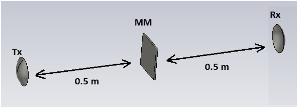
Model I considered for the study.

WPT system efficiency measurements for different configurations (Shashank and Nayak 2021).

Variation in WPT system efficiency for MM of different efficiencies (Model I).
In order to understand the effect of diameter of MM on WPT system efficiency, different diameters of MMs have been considered with 80 % efficiency and system efficiencies have been calculated at different locations from transmitter and shown in Figure 7. From the results, it is clear that the system efficiency increases with the increase in the diameter of MM for a given location of MM. Further, higher system efficiency is achieved at increased distance from transmitter for higher diameter MM. It is important to note that depending on diameter of MM, beyond certain distance from transmitter, WPT system efficiency falls down rapidly.
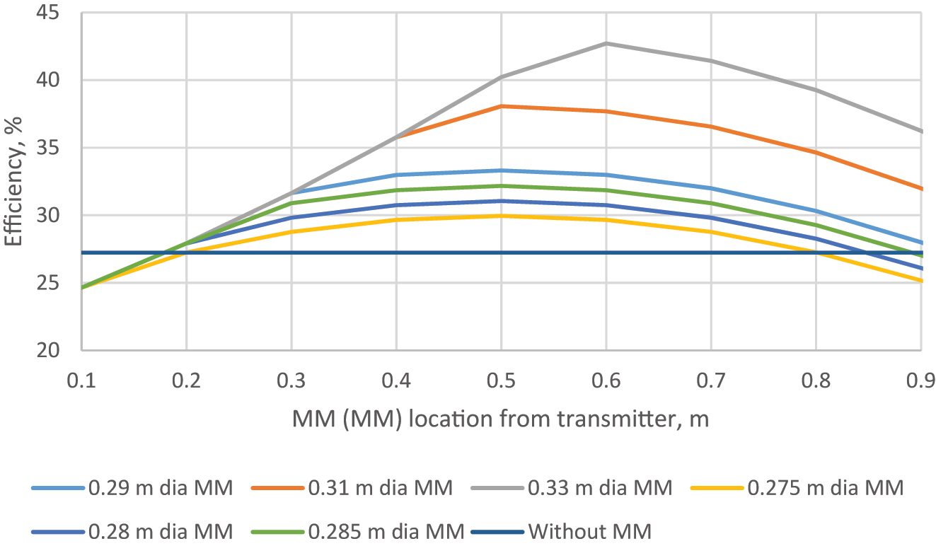
Variation in WPT system efficiency for MM of different diameters (Model I).
In order to understand effect of receiver location with respect to transmitter on system efficiency, a MM block of diameter 0.3 m with different efficiencies/absorption losses is fixed at 0.4 m from transmitter while the location of receiver from transmitter is varied. The results are shown in Figure 8. It is clear from results that the WPS system efficiency is higher with MM compared to without MM. It is also evident that as the WPS system efficiency increases with increase of efficiency of MM.

Variation in WPT system efficiency for a fixed MM of different efficiencies (Model I).
System efficiencies have been computed for different beam diameters of convergence from MM (20 % absorption loss or 80% efficiency) and shown in Figure 9. In other words, variation of system efficiencies has been plotted for different beam diameters at exit of MM of given diameter of MM. Here, the MM diameter of 0.29 m is considered and the beam diameter at exit of MM is varied from 0.23 m to 0.29 m. It is clear from the results that the efficiency falls down as the beam diameter at exit of MM increases (less convergence) and vice versa. From the results shown in above figure, it is apt to consider the beam diameter of 0.27 m (which is also transmitter diameter) at exit of MM for the analysis carried out for Model-I.
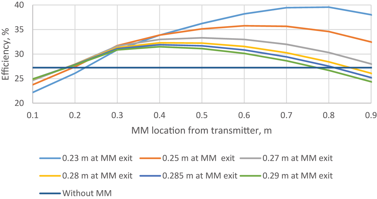
Variation of efficiency for different beam diameter of convergences of MM (Model I).
The Model II consisting of transmitter, receiver and MM array is as shown in Figure 10. The variation of power density with distance between transmitter (T x ) and receiver (R x ) is computed for second model considered in the study. The power density reduces with distance as the beam diverges, however, it starts increasing when the beam encounters MM. This may be because of the reason that the beam diameter converges within the MM. The received power is highest as long as the MM size is sufficient to capture the total beam and the receiver reflector size is sufficient to capture the total microwave beam. As the microwave beam is divergent, certain amount of microwave beam will be lost unless significant size receiver reflector i.e., at least transmitter size is used at the receiving end. The transmitter reflector size of 1.8 m diameter and efficiency of 70 %, the receiver reflector size of 1.8 m diameter, centre frequency of 2.45 GHz, two MMs of efficiency up to 80 %, diameter 2 m and thickness 0.01 m at 20 m and 40 m are considered for the analysis. The distance between transmitter and receiver is considered to be 60 m. It is assumed that when beam enters the MM with certain diameter, it shall leave the MM with diameter equal to the reflector diameter. Under this assumption, the negative refractive index variation with thickness of MM is calculated using equation (11) and plotted as shown in Figure 11. The lower the thickness of the MM, the lower will be the negative refractive index of the MM. The power density of microwave beam is compared for WPT system with and without MMs and shown in Figure 12. The power density of microwave beam without MM falls continuously as indicated and the power density of microwave beam shoots up when it encounters the MM. The peak value of power density with meta materials also reduces with increase of distance from transmitter depending on efficiency of meta materials. As shown in Figure 12, the system efficiency without MM falls down continuously with the increase in the distance of the location of the receiver from the transmitter because the receiver size of 1.8 m diameter may not be sufficient to capture all the microwave beam.

Model II considered for the study.

Variation of negative refractive index with thickness of MM (Model II).

Variation of power density of WPT system with and without MMs (Model II).
The variation of WPT system efficiency with and without MMs is shown in Figure 13. When the receiver is at 50 m distance from the transmitter, the system efficiency is 24.48 % (the received power is 489.57 W). In case of utilization of MMs, the received power by the receiver is improved significantly depending on location of receiver w.r.t. transmitter. For example, if the receiver is at 30 m and one MM is located at 20 m from the transmitter, the system efficiency is found to be 52.12 % (received power is 1042.40 W). Further, if the receiver is at 50 m after two MMs at an interval of 20 m, the system efficiency is found to be 41.69 % (received power is 833.8 W). Here, efficiency of MM is assumed to be 80 %. Thus, the received power of the WPT system with MMs is higher than the received power without MMs for a given location of the receiver from the transmitter. The received power by the receivers are computed for different sizes of the receivers assuming the same size of the transmitter and considering MMs of diameter 1.8 m. When the receiver size is same as the transmitter size, the received power starts falling from the transmitter itself. As the receiver size increases, and more than transmitter, the received power remains constant till certain distance from transmitter and then it starts falling when the microwave beam diameter exceeds the size of the receiver as shown in Figure 14. Here, efficiency of MMs is considered to be 80 %. From the results, it is clear that the received power at 60 m distance from transmitter is improved in the range of 690.53 W–746.88 W depending on receiver size, against 380.65 W for the configuration of WPT without meta material. For increased receiver size, there is a substantial increase in receiving power. The WPT system efficiency has also been computed by varying the MM location from the transmitter and keeping the receiver at 60 m distance from the transmitter as shown in Figure 15. It has been observed that the maximum efficiency of 24.81 % is achieved when the MM of 80 % efficiency is placed at around 30 m from the transmitter. Thus, the WPT system efficiency increases and reaches the peak value at half way of transmitter and receiver. Beyond this, system efficiency falls with increase of distance of MM location from the transmitter as shown in Figure 15.

Variation of efficiency of the WPT system with and without MMs (Model II).

Variation of received power for different receiver sizes (Model II).

Variation of efficiency with respect to MM location from transmitter (Model II).
In order to understand the effect of diameter of MM on WPT system efficiency, different diameters of MMs have been considered with 80 % efficiency and system efficiencies have been calculated at different locations and shown in Figure 16. From the results, it is clear that the system efficiency increases with the increase in the diameter of MM for the given location of MM. Further, higher system efficiency is achieved at greater distance from transmitter for higher diameter MM. It is important to note that depending on diameter of MM, beyond certain distance from transmitter, usually half way between transmitter and receiver, WPT system efficiency decreases.

Variation in WPT system efficiency for MM of various diameters (Model II).
The Model III consisting of transmitter, receiver and MM array is as shown in Figure 17. The analysis has been carried out for higher power transfer of 15 kW over a distance of 2.8 km (refer Model III). The transmitter reflector diameter of 12 m with efficiency of 70 % is considered for the analysis. The receiver reflector size of 12 m diameter, centre frequency of 2.45 GHz, MMs of diameter 13.37 m and thickness 0.01 m with separation of 800 m among them are considered for the analysis. The distance between the transmitter and receiver is 2800 m. It is assumed that the beam converges to 12 m diameter when it comes out of MM. The variation of system efficiency is computed with and without MMs and shown in Figure 18(a). Though there is an efficiency drop due to absorption loss of MM, the overall efficiency of WPT system has been greatly improved by using MMs at frequent intervals of distance between transmitter and receiver. WPT System efficiency falls down to 33.8 % at 2800 m with 80 % efficient MMs while the maximum system efficiency that can be achieved with 90 % efficient MMs (absorption loss is 10 %) is 48.1 % at same location. However, the system efficiency without MMs at 2800 m is 17.7 %, which is less compared to all the configurations in which MMs are used. The analysis has also been carried out by placing only one MM at 1600 m (refer Figure 18(b)) The chosen diameter of the MM is 16.81 m to ensure that all the microwave beam falls on the MM.

Model III considered for the study.

Variation of WPT system efficiency for 15 kW power with and without MMs. (a) MMs are placed at interval of 800 m (b) MMs is placed at 1600 m from transmitter (Model III).
Further, it is assumed that the beam converges to 12 m, when it comes out of MM. WPT System efficiency falls down to 36.3 % at 2800 m with 80 % efficient MMs while the maximum system efficiency that can be achieved with 90 % efficient MMs is 40.8 % at same location. In other words, diameter and location of MM affect the WPT system efficiency. With 90 % efficient MM is considered, WPT system efficiency is found to be more for the configuration of placement of MMs at every 800 m between transmitter and receiver. Whereas, when 80 % efficient MM is considered, WPT system efficiency is found to be more for the configuration of MM located at 1600 m from transmitter. Hence, WPT system efficiency has to be estimated for various configurations and efficiencies of MMs to arrive at its optimal value. In view of above, WPT system efficiency has been estimated by considering various distances among meta materials (refer Figure 19). The receiver is assumed to be at 2800 m from the transmitter. It is clear from the results that the MMs are placed at a distance span of 200 m, the WPT system efficiency is found to be 3.79 %. Highest WPT system efficiency is found to be 33.81 % (13.5 m MM is considered) for a configuration wherein the MMs are placed at a distance span of 800 m. When a MM is placed at 1600 m from transmitter, it is clear that the highest efficiency falls down to 24.1 %. From the analysis, it is evident that the highest efficiency can be achieved with MMs diameter of up to 14 m when they are located at a distance span of 800 m. Thus, this analyses help us to identify the optimal number of MMs to maximize WPT system efficiency for a particular size of transmitter and receiver.

Variation of WPT system efficiency with distance among MMs (Model III).
In order to understand the effect of location of MM on WPT system efficiency, different diameters of MMs have been considered with 80 % efficiency and system efficiencies have been calculated at different locations of MM (refer Figure 20). From the results, it is clear that the WPT system efficiency increases with the increase in the diameter of MM for the given location of MM. Further, higher system efficiency is achieved at greater distance from transmitter for higher diameter MM. It is important to note that depending on diameter of MM, beyond certain distance from transmitter, WPT system efficiency decreases irrespective of MM diameter. More clearly, for MMs located beyond halfway from transmitter, system efficiency start decreasing and reaches lowest levels when they are located near receiver.

Variation in WPT system efficiency for MMs located at different distances from transmitter (Model III).
Figure 21 shows variation of system efficiency for transmitter and receiver of different diameters and MMs of 80 % efficiency are placed at a distance span of 800 m. It is obvious from figure that the system efficiency at a given location increases with increase of diameter of transmitter and receiver. For instance, the system efficiency obtained with 7 m transmitter and receiver at 2800 m is 23.58 %. Similarly, the system efficiencies obtained with 12 m and 17 m transmitter at same location are 33.81 % and 35.31 % respectively. Thus, higher the size of the transmitter and receiver for a given diameter of MM, higher is the overall system efficiency. When a MM is placed at a distance of 1600 m from transmitter, it has been observed that system efficiencies obtained at 2800 m with 7 m, 12 m, 17 m transmitter and receiver are 9.86 %, 36.33 %, 49.36 % respectively.

Variation of efficiency with transmitter and receiver dimensions (Model III).
The Model IV consisting of transmitter, receiver and MM array is as shown in Figure 22. The analysis has also been carried out for Model IV configuration by considering the distance between transmitter and receiver as 8.4 km. Three MMs of diameter 22.6 m and thickness 0.01 m at a distance span of 2400 m between them are considered for the analysis. The transmitter and receiver diameters are considered to be 20 m. It is assumed that the beam converges to 20 m diameter when it comes out of MM. The variation of WPT System efficiency has been calculated for this configuration and shown in Figure 23. WPT system efficiency falls down to 15.77 % at 8400 m without MMs while the WPT system efficiency that can be achieved with 80 % efficient MMs is 33.49 %. The above analysis has been carried out for fixed locations of MMs and transmitter while the location of receiver is varied w.r.t. the transmitter. At the same time, it is also important to identify optimal location of MMs for fixed location of transmitter and receiver. Receiver is assumed to be fixed at 8.4 km distance from the transmitter. MM location is changed from transmitter to receiver in steps of 600 m. The variation of WPT system efficiency for different locations of MMs is as shown in Figure 24. It is evident from the results that highest system efficiency is quite possible when the MM location is prior to the midway of transmitter and receiver. Moreover, WPT system efficiency falls down with increase of distance of MM from transmitter beyond a particular location from transmitter. The analysis is repeated by considering the increased beam diameter of convergence to the diameter of MM. It is clear from the results that the efficiency falls down as the beam diameter at exit of MM increases and vice versa. It is further confirmed that, in order to obtain higher WPT system efficiency, converging beam diameter at the exit of MM shall be as low as possible.

Model IV considered for the study.

Variation of WPT system efficiency with and without MMs (Model IV).

Variation of WPT system efficiency with respect to MM location (Model IV).
6 Validation through FEM analysis
Finite Element Method (FEM) based model is developed for the proposed WPT system and analysis has been carried out for estimation of radiating power density. The horn antenna along with the reflector has been used as the transmitter. When the horn antenna port is excited with 0.5 W power, the radiated power is found to be 0.26 W. The variation of power density at a distance of 0.5 m is as shown in Figure 25. The average power density is estimated by calculating the total incident power over that plane through the software and dividing it with area of the plane. The variation of power density at various distances from the transmitter has been plotted and compared with the analytical results obtained using equations (3)–(7) as shown in Figure 26. It has been found that the maximum deviation between the analytical results and FEM results for power density is 9.2 %. The efficiency calculated through FEM software at various distances from the transmitter have been compared with the efficiency levels calculated using proposed analytical approach and shown in Figure 27. It is evident from analysis that the highest deviation between the analytical and FEM results for efficiency is about 9.8 %.

Variation of power density at 0.5 m distance from transmitter.

Variation of power density with distance from transmitter.

Variation of WPT system efficiency with distance from transmitter.
7 Conclusions
An alternate method has been proposed to determine the radiating power density and received power in the near-field zone by estimating the beam diameter. The beam diameter at a given distance in the Fresnel region has been systematically derived from the beam angle which is valid for far-field zone. It has been proved mathematically that the microwave beam which is divergent in nature converges when it encounters a MM with negative refractive index.
In the present paper, the variation of radiating power density, receiving power and WPT system efficiency with respect to location of receiver from transmitter is analysed and reported. The analysis has been made for various configurations of WPT system with and without MMs. For Model I configuration, the receiver is considered at 1 m distance from the transmitter. It is clear from the results that the WPT system efficiency without MM is 27.23 %. Further, WPT system efficiency increases and reaches the highest level (33.31 %) for the MM of 80 % efficiency, located at around 0.5 m from transmitter. WPT efficiency decreases as MM moves beyond 0.5 m distance from transmitter. The computed efficiency levels are in line with the experimental results referred in (Shashank and Nayak 2021). It is evident from analysis that the efficiency of WPT system with negative refractive index MMs is found to be improved significantly as compared to WPT system without MMs being used. Variation of system efficiencies has been calculated for different beam diameters at exit of MM of given diameter. Here, the MM diameter of 0.29 m is considered and the beam diameter at exit of MM is varied from 0.23 m to 0.29 m. It is clear from the results that the efficiency falls down as the beam diameter at exit of MM increases (less convergence) and vice versa. From the available experimental results (Shashank and Nayak 2021), it is apt to consider the beam diameter of 0.27 m (which is also transmitter diameter) at exit of MM for the analysis carried out for Model-I.
For Model II configuration, when the receiver is at 50 m distance from the transmitter, the system efficiency is 24.48 % (the received power is 489.57 W). In case of utilization of MMs, the received power by the receiver is improved significantly depending on location of receiver w.r.t. transmitter. For a particular system configuration, if the receiver is at 30 m and one MM is located at 20 m from the transmitter, the system efficiency is found to be 52.12 % (received power is 1042.40 W). Similarly, if the receiver is at 50 m after two MMs at an interval of 20 m, the system efficiency is found to be 41.69 % (received power is 833.8 W). Here, efficiency of MM is assumed to be 80 %.
For Model-III configuration, when MMs are placed at a distance span of 800 m, WPT system efficiency falls down to 33.8 % at 2800 m with 80 % efficient MMs while the maximum system efficiency that can be achieved with 90 % efficient MMs is 48.1 % at same location. When one MM is placed at 1600 m, WPT system efficiency falls down to 36.3 % at 2800 m with 80 % efficient MM while the maximum system efficiency that can be achieved with 90 % efficient MM is 40.8 % at same location. Hence, the WPT system efficiency has to be estimated for various configurations of MMs including various efficiencies to arrive at optimal WPT system efficiency. When the MMs are placed at a distance span of 200 m, the WPT system efficiency is found to be 3.79 %. In other words, even though many number of MMs are used, the system efficiency reduces significantly due to cumulative loss of MMs. For Model-IV configuration, WPT System efficiency falls down to 15.77 % at 8400 m without MMs while the WPT system efficiency that can be achieved with 80 % efficient MMs is 33.49 %. It is evident from the results that highest system efficiency is quite possible when the MM location is prior to the midway of transmitter and receiver. Further, WPT system efficiency falls down with increase of distance of MM from transmitter beyond a particular location from transmitter.
Finally, FEM based analysis has been carried out for basic WPT system model and the variation of power density and efficiency at various distances from transmitter has been plotted and compared with the analytical results. It has been found that the maximum deviation between the proposed analytical and FEM based computational results for power density and WPT system efficiency are 9.2 % and 9.8 % respectively.
-
Author contributions: All the authors have accepted responsibility for the entire content of this submitted manuscript and approved submission.
-
Research funding: None declared.
-
Conflict of interest statement: The authors declare no conflicts of interest regarding this article.
References
Brown, W. C., and E. Eves. 1992. “Beamed Microwave Power Transmission and its Application to Space.” IEEE Transactions on Microwave Theory and Techniques 40 (6): 1239–50. https://doi.org/10.1109/22.141357.Suche in Google Scholar
Breinbjerg, O., and K. Kaslis. 2017. “On the Accuracy of Friis’ Transmission Formula at Short Range.” In XXXIInd General Assembly and Scientific Symposium of the International Union of Radio Science (URSI GASS), 1–2.10.23919/URSIGASS.2017.8105036Suche in Google Scholar
Chu, T. S. 1965. “An Approximate Generalization of the Friis Transmission Formula.” Proceedings of the IEEE 53 (3): 296–7. https://doi.org/10.1109/proc.1965.3688.Suche in Google Scholar
Franceschetti, G., A. Massa, and P. Rocca. 2011. “Innovative Antenna Systems for Efficient Microwave Power Collection.” In Proceedings of the 2011 IEEE MTT-S International Microwave Workshop Series on Innovative Wireless Power Transmission: Technologies, Systems, and Applications, 275–8. Piscataway: IEEE.10.1109/IMWS.2011.5877080Suche in Google Scholar
Gowda, V. R., O. Yurduseven, G. Lipworth, T. Zupan, M. S. Reynolds, and D. R. Smith. 2016. “Wireless Power Transfer in the Radiative Near Field.” IEEE Antennas and Wireless Propagation Letters 15: 1865–8. https://doi.org/10.1109/lawp.2016.2542138.Suche in Google Scholar
Ghobad, P. C., and R. M. de Moraes. 2012. “BER Analysis with an Appropriate Friis Formula for Multi-Hop ALOHA Dense Ad Hoc Networks.” In IEEE Vehicular Technology Conference (VTC Fall), 1–5.10.1109/VTCFall.2012.6398957Suche in Google Scholar
Hogg, D. C. 1993. “Fun with the Friis Free-Space Transmission Formula.” IEEE Antennas and Propagation Magazine 35 (4): 33–5. https://doi.org/10.1109/74.229847.Suche in Google Scholar
Juengkittikul, P., and S. Promwong. 2009. “Evaluation of the Complex Form in Fresnel Region for UWB Free Space Transmission Model.” In IEEE International Conference on Telecommunications and Malaysia Communications, 263–6.10.1109/MICC.2009.5431509Suche in Google Scholar
Kawasaki, S. 2011. “Microwave WPT to a Rover Using Active Integrated Phased Array Antennas.” In Proc. Eur. Conf. Antennas Propag., 3909–12.Suche in Google Scholar
Kim, I., S. Xu, and Y. Rahmat-Samii. 2013. “Generalized Correction to the Friis Formula: Quick Determination of the Coupling in the Fresnel Region.” IET Microwaves, Antennas & Propagation 7 (13): 1092–101. https://doi.org/10.1049/iet-map.2013.0131.Suche in Google Scholar
Kim, S. G., J. H. Kim, D. Kim, W. S. Lee, W. Jang, and E. Choi. 2015. “A Novel Method for Power Measurement of a Short Pulse Gyrotron Using Friis Transmission Formula at W-Band.” In 40th International Conference on Infrared, Millimeter, and Terahertz waves (IRMMW-THz), 1.10.1109/IRMMW-THz.2015.7327807Suche in Google Scholar
Kim, Y., S. Boo, G. Kim, N. Kim, and B. Lee. 2019. “Wireless Power Transfer Efficiency Formula Applicable in Near and Far Fields.” Journal of the Korean Institute of Electromagnetic Engineering and Science 19 (4): 239–44. https://doi.org/10.26866/jees.2019.19.4.239.Suche in Google Scholar
Li, Y., and V. Jandhyala. 2012. “Design of Retrodirective Antenna Arrays for Short-Range Wireless Power Transmission.” IEEE Transactions on Antennas and Propagation 60: 206–11. https://doi.org/10.1109/tap.2011.2167897.Suche in Google Scholar
Lee, H., S. Boo, G. Kim, and B. Lee. 2020. “Optimization of Excitation Magnitudes and Phases for Maximum Efficiencies in a MISO Wireless Power Transfer System.” Journal of Electromagnetic Engineering and Science 20 (1): 16–66. https://doi.org/10.26866/jees.2020.20.1.16.Suche in Google Scholar
Manica, L., P. Rocca, A. Martini, and A. Massa. 2008. “An Innovative Approach Based on a Tree-Searching Algorithm for the Optimal Matching of Independently Optimum Sum and Difference Excitations.” IEEE Transactions on Antennas and Propagation 56: 58–66. https://doi.org/10.1109/tap.2007.913037.Suche in Google Scholar
Merrill, I. 2002. Skolnik, Reference Data for Engineers, 9th ed. England: Newnes.Suche in Google Scholar
Oliveri, G., P. Rocca, F. Viani, F. Robol, and A. Massa. 2012. “Latest Advances and Innovative Solutions in Antenna Array Synthesis for Microwave Wireless Power Transmission.” In Proceedings of the 2012 IEEE MTT-S International Microwave Workshop Series on Innovative Wireless Power Transmission: Technologies, Systems, and Applications, 71–3. Piscataway: IEEE.10.1109/IMWS.2012.6215822Suche in Google Scholar
Otsuka, M., N. Omuro, K. Kakizaki, S. Saitoh, M. Kuroda, K. Horiuchi, and T. Soejima. 1990. “Relation between Spacing and Receiving Efficiency of Finite Rectenna Array (In Japanese).” IEICE Trans B-II J74-B-II (3): 133–9.10.1002/ecja.4410740210Suche in Google Scholar
Shinohara, N., Y. Kubo, and H. Tonomura. 2013. “Mid-distance Wireless Power Transmission for Electric Truck via Microwaves.” Proc. URSI Int. Symp. Electromagn. Theory: 841–3.Suche in Google Scholar
Shinohara, N. 2012. “Recent Wireless Power Transmission via Microwave and Millimeter-Wave in Japan.” Proc. IEEE Microw. Conf. 20: 7843–8.10.23919/EuMC.2012.6459095Suche in Google Scholar
Smith, D. R., J. B. Pendry, and M. C. K. Wiltshire. 2004. “Metamaterials and Negative Refractive Index.” Science 305: 788. https://doi.org/10.1126/science.1096796.Suche in Google Scholar PubMed
Shashank, S., and S. K. Nayak. 2021. “Kulkarni, Amit Kumar Baghel, Sisir Kumar Nayak, “Graded Refractive Index Metamaterial for Enhanced Far-Field Wireless Power Transfer Efficiency in S-Band”.” AEU - International Journal of Electronics and Communications 138: 153859. https://doi.org/10.1016/j.aeue.2021.153859.Suche in Google Scholar
Shinohara, N. 2010. “Beam Efficiency of Wireless Power Transmission via Radio Waves from Short Range to Long Range.” Journal of the Korean Institute of Electromagnetic Engineering and Science 10 (4): 224–30. https://doi.org/10.5515/jkiees.2010.10.4.224.Suche in Google Scholar
Trichili, A., M. A. Cox, B. S. Ooi, and M.-S. Alouini. 2020. “Road Map to Free Space Optics.” Journal of the Optical Society of America B 37: A184–201, https://doi.org/10.1364/josab.399168.Suche in Google Scholar
Udomsom, S., T. Yooyativon, R. Chaisricharoe, C. Kamyod, and S. Promwong. 2017. “A Novel Analysis of IR-WPAN Transmission Using Friis’ Transmission Formula.” In 14th International Conference on Electrical Engineering/Electronics, Computer, Telecommunications and Information Technology (ECTI-CON), 818–21.10.1109/ECTICon.2017.8096364Suche in Google Scholar
Wang, B., T. Nishino, and K. H. Teo. 2010. “Wireless Power Transmission Efficiency Enhancement with Metamaterials.” In Proceedings of the IEEE International Conference on Wireless Information Technology and Systems (ICWITS’10). Honululu.Suche in Google Scholar
Yang, X., G. Wen, and H. Sun. 2017. “Optimum Design of Wireless Power Transmission System Using Microstrip Patch Antenna Arrays.” IEEE Antennas and Wireless Propagation Letters 16: 1824–7.10.1109/LAWP.2017.2682262Suche in Google Scholar
© 2024 the author(s), published by De Gruyter, Berlin/Boston
This work is licensed under the Creative Commons Attribution 4.0 International License.
Artikel in diesem Heft
- Solar photovoltaic-integrated energy storage system with a power electronic interface for operating a brushless DC drive-coupled agricultural load
- Analysis of 1-year energy data of a 5 kW and a 122 kW rooftop photovoltaic installation in Dhaka
- Reviews
- Real yields and PVSYST simulations: comparative analysis based on four photovoltaic installations at Ibn Tofail University
- A comprehensive approach of evolving electric vehicles (EVs) to attribute “green self-generation” – a review
- Exploring the piezoelectric porous polymers for energy harvesting: a review
- A strategic review: the role of commercially available tools for planning, modelling, optimization, and performance measurement of photovoltaic systems
- Comparative assessment of high gain boost converters for renewable energy sources and electrical vehicle applications
- A review of green hydrogen production based on solar energy; techniques and methods
- A review of green hydrogen production by renewable resources
- A review of hydrogen production from bio-energy, technologies and assessments
- A systematic review of recent developments in IoT-based demand side management for PV power generation
- Research Articles
- Hybrid optimization strategy for water cooling system: enhancement of photovoltaic panels performance
- Solar energy harvesting-based built-in backpack charger
- A power source for E-devices based on green energy
- Theoretical and experimental investigation of electricity generation through footstep tiles
- Experimental investigations on heat transfer enhancement in a double pipe heat exchanger using hybrid nanofluids
- Comparative energy and exergy analysis of a CPV/T system based on linear Fresnel reflectors
- Investigating the effect of green composite back sheet materials on solar panel output voltage harvesting for better sustainable energy performance
- Electrical and thermal modeling of battery cell grouping for analyzing battery pack efficiency and temperature
- Intelligent techno-economical optimization with demand side management in microgrid using improved sandpiper optimization algorithm
- Investigation of KAPTON–PDMS triboelectric nanogenerator considering the edge-effect capacitor
- Design of a novel hybrid soft computing model for passive components selection in multiple load Zeta converter topologies of solar PV energy system
- A novel mechatronic absorber of vibration energy in the chimney
- An IoT-based intelligent smart energy monitoring system for solar PV power generation
- Large-scale green hydrogen production using alkaline water electrolysis based on seasonal solar radiation
- Evaluation of performances in DI Diesel engine with different split injection timings
- Optimized power flow management based on Harris Hawks optimization for an islanded DC microgrid
- Experimental investigation of heat transfer characteristics for a shell and tube heat exchanger
- Fuzzy induced controller for optimal power quality improvement with PVA connected UPQC
- Impact of using a predictive neural network of multi-term zenith angle function on energy management of solar-harvesting sensor nodes
- An analytical study of wireless power transmission system with metamaterials
- Hydrogen energy horizon: balancing opportunities and challenges
- Development of renewable energy-based power system for the irrigation support: case studies
- Maximum power point tracking techniques using improved incremental conductance and particle swarm optimizer for solar power generation systems
- Experimental and numerical study on energy harvesting performance thermoelectric generator applied to a screw compressor
- Study on the effectiveness of a solar cell with a holographic concentrator
- Non-transient optimum design of nonlinear electromagnetic vibration-based energy harvester using homotopy perturbation method
- Industrial gas turbine performance prediction and improvement – a case study
- An electric-field high energy harvester from medium or high voltage power line with parallel line
- FPGA based telecommand system for balloon-borne scientific payloads
- Improved design of advanced controller for a step up converter used in photovoltaic system
- Techno-economic assessment of battery storage with photovoltaics for maximum self-consumption
- Analysis of 1-year energy data of a 5 kW and a 122 kW rooftop photovoltaic installation in Dhaka
- Shading impact on the electricity generated by a photovoltaic installation using “Solar Shadow-Mask”
- Investigations on the performance of bottle blade overshot water wheel in very low head resources for pico hydropower
- Solar photovoltaic-integrated energy storage system with a power electronic interface for operating a brushless DC drive-coupled agricultural load
- Numerical investigation of smart material-based structures for vibration energy-harvesting applications
- A system-level study of indoor light energy harvesting integrating commercially available power management circuitry
- Enhancing the wireless power transfer system performance and output voltage of electric scooters
- Harvesting energy from a soldier's gait using the piezoelectric effect
- Study of technical means for heat generation, its application, flow control, and conversion of other types of energy into thermal energy
- Theoretical analysis of piezoceramic ultrasonic energy harvester applicable in biomedical implanted devices
- Corrigendum
- Corrigendum to: A numerical investigation of optimum angles for solar energy receivers in the eastern part of Algeria
- Special Issue: Recent Trends in Renewable Energy Conversion and Storage Materials for Hybrid Transportation Systems
- Typical fault prediction method for wind turbines based on an improved stacked autoencoder network
- Power data integrity verification method based on chameleon authentication tree algorithm and missing tendency value
- Fault diagnosis of automobile drive based on a novel deep neural network
- Research on the development and intelligent application of power environmental protection platform based on big data
- Diffusion induced thermal effect and stress in layered Li(Ni0.6Mn0.2Co0.2)O2 cathode materials for button lithium-ion battery electrode plates
- Improving power plant technology to increase energy efficiency of autonomous consumers using geothermal sources
- Energy-saving analysis of desalination equipment based on a machine-learning sequence modeling