Investigation of KAPTON–PDMS triboelectric nanogenerator considering the edge-effect capacitor
-
Mohsen Keykha
 und
Ali Mohammadi
und
Ali Mohammadi

Abstract
Harvesting the dissipated environmental mechanical energy to generate electrical energy is subject of the new research in the field of clean energy. In this paper, a triboelectric nanogenerator based on vertical two-electrode structure was fabricated using KAPTON and PDMS polymers. The nanogenerator outputs were measured and plotted by applying a mechanical vibration with the frequency of 8 Hz. The results indicated the ability of producing a voltage of 3.5 V and a current of 0.025 μA by this nanogenerator. To effectively simulate the performance of the device in different structural and environmental conditions, the ordinary capacitance model of the device was modified considering three effective capacitances. The simulation results showed a very good agreement between calculated and actual outputs when the edge effect capacitor was included in the ordinary model. Finally, based on the corrected model for the nanogenerator, the effect of the environmental conditions on the device output was studied. The innovative point of this text is the investigation of the effect of edge capacitors in the performance of triboelectric nanogenerators, and it has also been tried to collect a collection of studies that I have done in the field of triboelectric nanogenerators.
1 Introduction
In today’s world, the use of the renewable energy as an alternative to the fossil fuels is important and essential. Among these energies, dissipative mechanical vibrations and accidental environmental movements are as the most common types of energies that exist in everyday life (Dresselhaus et al. 2001; Kolar 2000). In this regard, nanogenerators based on intrinsic materials properties, such as piezoelectric, electromagnetic, thermoelectric, triboelectric etc. are vastly considered in new researches. The device based on mentioned effects are activated by environmental motions and vibrations and convert them into useful electrical energy (Wang et al. 2006; Xu et al. 2011). Small area nanogenerators can be used in self-power sensors and actuators and wireless microelectronic systems. However, in larger scales, they can be used also, for producing the domestic electrical power. Among them, triboelectric nanogenerators (TENGs) are fabricated based on transport of the electrons between two different materials due to the triboelectric effect (Wang, Lin, and Wang 2012). The performance of TENGs is influenced by the type of materials used. In this regards, the polymeric materials such as KAPTON, PVC, PET and PDMS have been used more often in the recent research to fabricate triboelectric nanogenerators (Wang, Lin, and Wang 2012). Among the other reasons for choosing the mentioned materials in the structure of this nanogenerator are that: these materials are found very easily and at low cost in nature, and these materials are nature-friendly and will not harm the environment if left in nature. It is shown that the use of KAPTON–PET couples, in comparison to PVC–PET couples, produces more power at the output of the nanogenerator (Fan, Tian, and Wang 2012). The performance mechanism of a two electrodes contact TENG has been already modeled, where the actual and theoretical results were compared (Niu et al. 2013). To extract the maximum power from the nanogenerator, the required optimal External load has been also calculated. To study the TENG performance, usually a variable capacitor has been used as the model for TENG, and based on, the governing theory has been extracted (Niu et al. 2013, 2014; Wang et al. 2014). The effect of various parameters has been also considered to complete the investigation of TENG performance. However, multiple other capacitive and non-capacitive elements are existed that can affect the performance of the nanogenerator, which are not considered in previous studies. In the present study, with the use of KAPTON–PDMS polymers couple, a triboelectric nanogenerator is fabricated and its performance are studied experimentally and analytically. An investigation is made to correct the primary model with respect to the edge capacitor. Using the TENG model, the effect of various parameters such as changing in air gap and in the capacitance of the device and the environmental conditions are studied, too.
2 Experimental procedure
2.1 Materials and design
A nanogenerator structure of Electrode1/KAPTON/Air/PDMS/Electrode2, schematically shown in Figure 1, is considered and fabricated. The cross-sectional area of the device is 2 × 2 cm2 and aluminum and copper is used for the electrodes 1 and 2, respectively. Table 1 shows the size and some other important properties of the applied polymeric materials.

Schematic of the fabricated TENG.
Material properties and structural parameters of the triboelectric nanogenerator.
| Materials used/characteristic | MAT 1: PDMS | MAT 2: KAPTON |
|---|---|---|
| Thickness | 100 µm | 100 nm |
| Dielectric coefficient | 2.5 | 3.4 |
| Density of matter | 0.97 kg/m3 | 1.42 g/cm3 |
| Tensile strength | 2.23 MPa | 231 MPa |
To fabricate the device, PDMS film was first synthesis with a pyramidal structure. Such a pattern and its sharp points at the top is used to enhance the electron loss from the material. To have such a film, the PDMS liquid and its hardening were mixed with a ratio of 1:10. Then to have a uniform and homogeneous film, bubble blowing was done under vacuum condition for 1 h. Then the gel-like mixture was pour in a mold with a pyramidal pattern. The PDMS and mold were put in a furnace and cure at 80 °C for 1 h. After that, the pyramidal patterned PDMS was peeled off. Then the film was connected to the aluminum electrode using silver adhesive. The resulted structure is shown in Figure 2, right. For the upper layer, KAPTON was connected to the copper electrode using silver adhesive. Finally, the electrodes were wired to measure the nanogenerator outputs.

Image of the pyramidal patterned PDMS layer on Al contact (right) and the upper and bottom layers of TENG with the electrodes and the separators (left).
2.2 Experimental process
To actuate the nanogenerator, a reciprocating linear moving mechanism was designed and an instrument was fabricated to generate the necessary periodic compressive loading forces. The fabricated instrument and its working mechanism is shown in Figure 3. The device will applied linear vibration forces with desired frequencies on the nanogenerator. Then the output (voltage and current) of nanogenerator was measured using an accurate dual channel multimeter.

Fabricated instrument for applying force on device (left) and the schematic of the reciprocating linear moving mechanism for generating the vibration forces (right).
3 Mathematical formulation and modeling procedure
The generated electrical potential by TENG arises from two parts, as seen in Eq. (1) (Niu et al. 2013). The first one is V oc(x) (open circuit voltage) that is corresponding to the polarized triboelectric charges. The second part comes from the intrinsic capacitor behavior of TENG. These two parts generate a total output voltage V at the output terminals.
Base this equation, the ordinary model for a TENG is a variable capacitance. Here, an electrical circuit for TENG and the output load is plotted in Figure 4.
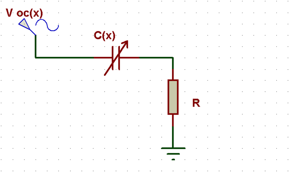
Equivalent electrical circuit for TENG with a resistive load.
So Eq. (1) can be written as:
This first order-order differential equation is integrated based on the following conditions (Lowell 1976):
at t = 0 and t = T; Q = 0
Where T is period of actuating forces.
Using the above relationships, the output current and voltage of the device were calculated where the flowchart of modeling procedure is shown in Figure 5.
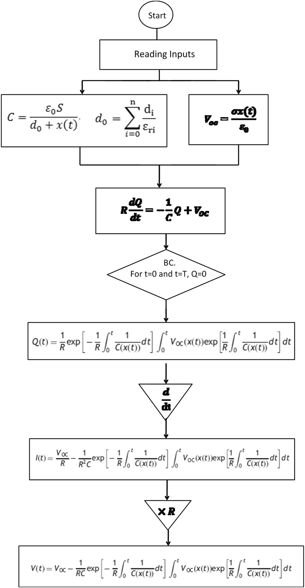
A flowchart for TENG modeling and the outputs calculations.
4 Result and discussion
4.1 Comparison of experimental results and simulation of KAPTON–PDMS nanogenerators
To study the performance of the nanogenerators external forces with a frequency of 8 Hz were applied on the top side of TENG using the fabricated instrument. The output results are plotted in Figure 8 (dashed lines). Exerting forces on the top of the nanogenerator deflect the PDMS and KAPTON layers and cause to slide over each other with particular frictions. The latter causes charge transfers between two dielectric layer. Same number of opposite charges induces on the electrodes and generate an electrical potential between them. As seen, fabricated nanogenerator is well responded to the exerting forces and its frequency. A maximum of about 3 V and a current of 0.02 μA is generated. Also, the simulation results for the modeled TENG are included to Figure 6 (Solid lines). The charges rate on the electrodes are shown in Figure 7. As shown with starting exerting forces, in a very short time, the charges on the electrodes increases and reaches to its maximum value. The maximum stored electric charge on the electrodes for such a nanogenerator is about 18 μC due to the transfer of electrons between the two polymers dielectric layers. Exerting external forces charges and discharges the electrodes corresponding to the external forces frequency.

KAPTON–PDMS nanogenerator output voltage and current, experimental results (dashed lines) and simulation results (solid lines).

Charges rate on the PDMS–KAPTON nanogenerator electrodes

Capacitive capacitance changes between plates.
4.2 Calculation and study of the capacitance property of the device
Understanding the nanogenerator responses to the effective design parameters can help to improve its performance. Thus in this section the effects of electric charging rate of the capacitance, air gap between the electrodes and its equivalent of the capacitance, are numerically studied. Figure 8 shows the capacitance change rate generated between the two layers of KAPTON and PDMS. As you can see, there is initially a capacitive capacity between the 4.5 nF plates, which gradually decreases the amount of capacitive capacity as the plates become closer to each other due to the force applied and the air gap between the plates is zero.
In Figure 9, the change in the induced charge on the electrodes of the triboelectric nanogenerator is plotted in terms of air gap variation. As can be seen, with increasing airborne variations from 0 to 12 mm, the induced charge increased from zero to 11 nC. This indicates that the nanogenerator plates are detached from each other after contact and are storing electrical charges on the plates. With each recurrence, this induced electric charge will be evacuated to the nanogenizer as an electrical current in the connected resistance load.
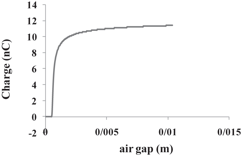
Changing the charge load induced on the electrodes of the tribo-electric nanogenerator in terms of air gap variation.
As shown in Figure 10, an increase in airspace will reduce the capacitance between the plates. The increase in air distance from 0 to 10 mm makes the capacitance change from 0.45 nF to 0.05 nF.
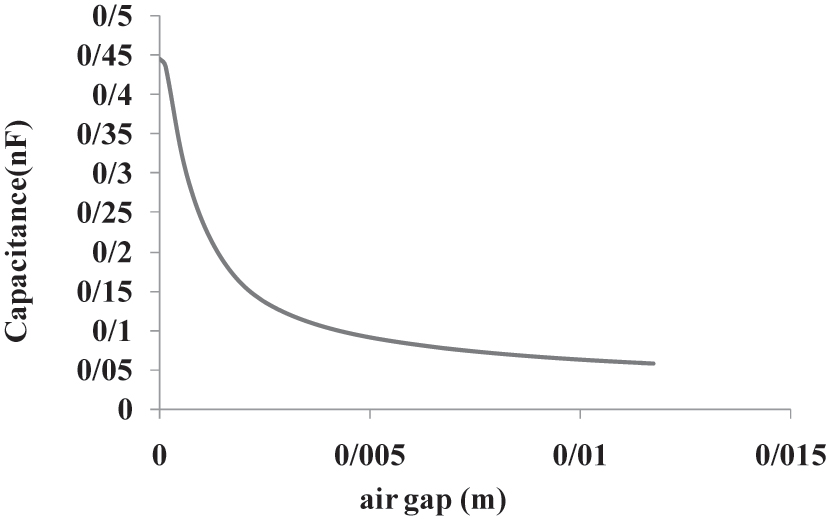
Capacitive capacitance change between triboelectric nano-generator plates in terms of air gap variation.
Other studies have shown that the relationship between induced charge and capacitive capacitance changes can be considered. As shown in Figure 11, increasing capacitance leads to a reduction in the stored charge on the plates.

Changing the electrical charge induced on the electrodes in terms of the capacitance induced between the triboelectric nanogenerator plates.
If we want to draw a general conclusion from diagrams 9, 10 and 11, it can be concluded that if the air gap between the plates is considered, a lower capacitance will be generated, which results in a higher induced charge and a better outflow current. We will be In the present study, this air gap is considered to be around 3 mm due to production limits of about 0.015 mA.
4.3 Correction of capacitor effect of triboelectric nanogenerator by edge capacitor
In the last approach, it is assumed that the distance between the electrodes was the same entire the electrodes surfaces and the two electrodes remains parallel after exerting the external force. So, the theory used to analyze the behavior of a triboelectric nanogenerator was considered only by the variable capacitor with the air gap between the two triboelectric layers, and the bending of the plates was taken uniformly. However usually the applied forces are not uniform and therefore the distances between the electrodes is not uniform. This situation is shown in Figure 12.

Non-uniform bending of the triple-electric layers when inserting force.
Since the dielectric to dielectric contact mode model has been used to construct the triboelectric nanogenerator, the capacitance diagram for this structure can be considered as shown in Figure 13. In this figure, C(x) is the variable capacitance with an air gap distance, the capacitors C fring1 (x) and C fring2 (x) are edge-effect capacitors.
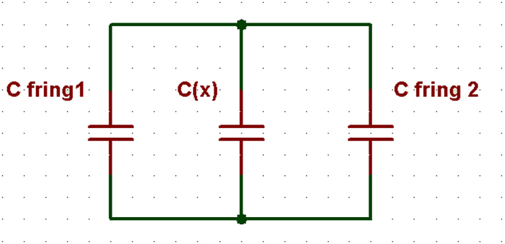
Corrected capacitive diagram for triboelectric nanogenerator.
Therefore, the foregoing model for calculating the triboelectric capacitor must be corrected, since the edge effects cause the capacitor to be different in the corners than the points affected by the force. For a symmetrical surface with a height H and width W, taking into account the effect of the edge, a triboelectric capacitor can be modified as:
Where H is height at the corner, W is width, ε ri is the relative dielectric coefficient of the surface, d i is the thickness of the layers and w = W − H/2. So, the value of capacitor that was used in equations (3) and (4) should be replaced by equation (7):
The result of the re-simulation with corrected capacitive relations is shown in Figure 14.

KAPTON–PDMS nanogenerator output voltage and current, experimental results (dashed lines) and modified simulation results (solid lines).
It is observed that the diagrams after correction of the capacitance, taking into account the edge effect, are better than the voltage and current diagrams in Section 6.1, and the diagrams obtained from the simulation and the laboratory results are closer to each other.
4.4 Effect of the environmental conditions on triboelectric nanogenerator voltage
Based on environmental conditions such as air pressure and temperature variations, the tribolectric nanogenerator test will respond to the environmental conditions of the nano-generator. The triboelectric principle consists of two electron displacement and ion displacement effects. The displacement of the bars depends on the connection between the polymer and the metal electrode, which is also related to the work of the metal electrode (Lowell 1976). Also, the presence of wet layers on the polymer surface can also be effective in the displacement of ions (Pence, Novotny, and Diaz 1994; Wiles et al. 2004). The effect of air pressure change can also affect the number of residual loads on the polymer surfaces. Based on experiments (McCarty et al. 2008), it was observed that between polymer and metal, up to 1 μTorr pressure, and for superfluid at pressures of 5 Torr (McCarty et al. 2008), surface loads remain stationary. Therefore, it can be concluded that atmospheric pressures and different temperature conditions can control the displacement of loads. As seen in Figure 15, with an increase in ambient pressure of 200–600 Torr, it will increase the voltage response of the tribo-electric nanogenerator. Also, as shown in Figure 16, the temperature increase will have a negative effect on the response of the triboelectric nanogenerator, as it is observed that with increasing temperature from 25 °C to 70 °C, the voltage of the triboelectric nanogenerator is reduced from 3.5 V to 1 V. It is worth mentioning that the test conditions and parameters of the nanogenerator are in accordance with Table 1.
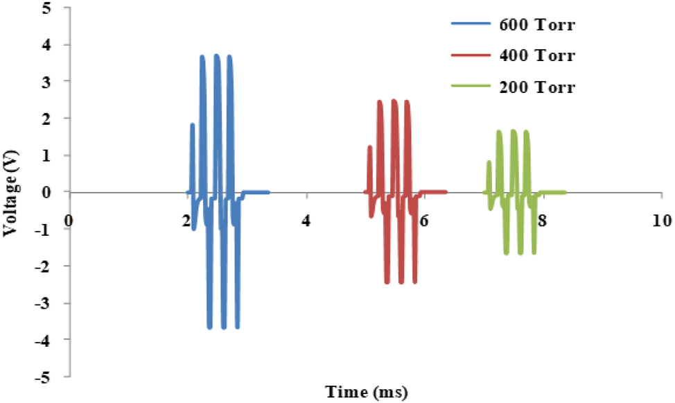
Effect of the ambient pressure on the output voltage of the triboelectric nanogenerator.

Effect of the ambient temperature on the output voltage of the triboelectric nanogenerator.
Another parameter that can be considered is the behavior of the triboelectric nanogenerator, which changes the thickness of the triple-electric layers. As shown in Figure 17, reducing the thickness of the layers used in the triboelectric nanogenerator structure will improve the performance of the nano-generator, reducing the thickness of the KAPTON layer from 100 μm to 10 nm, the output voltage will increase from 0.9 V to 2.5 V.

Effect of the thickness of the KAPTON layer on the output voltage of the triboelectric nanogenerator.
5 Conclusions
In this paper, a vertical triboelectric nanogenerator was fabricated and studied based on the various structural and environmental conditions. The device was able to generate a voltage of about 3.5 V and a current of 0.025 μA/cm2. Calculation and Investigation of the capacitance property of the nanogenerator showed that selecting the appropriate air gap between the two triboelectric layers leads to an increase in the electric charge transferred to the external circuit. In addition, with the smaller thicknesses for the dielectric material, the output voltage was increased. Considering the environmental conditions, it was shown that the air pressure, air temperature and humidity affect the displacement of the charges between the polymeric layers. The latter was investigated by study the effects of environmental conditions on the response of the triboelectric nanogenerator, and it was resulted that increasing ambient air pressure improves the performance of the triboelectric nanogenerator, while the increase in temperature have negative effect on the device performance. The obtained results are important for designing the vertical triboelectric nanogenerator as well as considering the best application environment for the device.
Acknowledgments
The authors are grateful to Zahedan University.
-
Research ethics: Not applicable.
-
Author contributions: Study conception and design: MK. Acquisition of data: MK, and ATB. Statistical analysis: MK. Drafting of the manuscript: MK and ATB. Critical revision of the manuscript: ATB. Supervision: MK and ATB. All authors contributed to the article and approved the submitted version. All authors read and approved the final manuscript. The authors have accepted responsibility for the entire content of this manuscript and approved its submission.
-
Competing interests: The authors states no conflict of interest.
-
Research funding: None declared.
-
Data availability: The original data used in the study are all included in the article, further inquiries can be directed to the corresponding author.
References
Dresselhaus, M. S., and I. L. Thomas. 2001. “Flexible Triboelectric Generator.” Nature 414: 6861–332.10.1038/35104599Suche in Google Scholar PubMed
Fan, F.-R., Z.-Q. Tian, and Z. L. Wang. 2012. “Flexible Triboelectric Generator.” Nano Energy 1 (2): 328–34. https://doi.org/10.1016/j.nanoen.2012.01.004.Suche in Google Scholar
Kolar, J. L. 2000. “Alternative Energy Technologies.” Environment Quarterly 10: 45. https://doi.org/10.1002/1520-6483(200024)10:2<45::aid-tqem6>3.0.co;2-p.10.1002/1520-6483(200024)10:2<45::AID-TQEM6>3.0.CO;2-PSuche in Google Scholar
Lowell, J. 1976. “The Electrification of Polymers by Metals.” Journal of Physics D: Applied Physics 9 (11): 1571. https://doi.org/10.1088/0022-3727/9/11/006.Suche in Google Scholar
McCarty, L. S., and G. M. Whitesides. 2008. “Electrostatic Charging Due to Separation of Ions at Interfaces: Contact Electrification of Ionic Electrets.” Angewandte Chemie International Edition 47 (12): 2188–207. https://doi.org/10.1002/anie.200701812.Suche in Google Scholar
Niu, S., S. Wang, L. Lin, Y. Liu, Y. S. Zhou, and Y. Hu. 2013. “Theoretical Study of Contact-Mode Triboelectric Nanogenerators as an Effective Power Source.” Energy & Environmental Science 6 (12): 3576–83, https://doi.org/10.1039/c3ee42571a.Suche in Google Scholar
Niu, S., Y. S. Zhou, S. Wang, Y. Liu, L. Lin, Y. Bando, and Z. L. Wang. 2014. “Simulation Method for Optimizing the Performance of an Integrated Triboelectric Nanogenerator Energy Harvesting System.” Nano Energy 8: 150–6, https://doi.org/10.1016/j.nanoen.2014.05.018.Suche in Google Scholar
Pence, S., V. Novotny, and A. Diaz. 1994. “Effect of Surface Moisture on Contact Charge of Polymers Containing Ions.” Langmuir 10 (2): 592–6. https://doi.org/10.1021/la00014a042.Suche in Google Scholar
Wang, Z. L., and J. Song. 2006. “Piezoelectric Nanogenerators Based on Zinc Oxide Nanowire Arrays.” Science 312 (5771): 242–6. https://doi.org/10.1126/science.1124005.Suche in Google Scholar
Wang, S., L. Lin, and Z. L Wang. 2012. “Nanoscale Triboelectric-Effect-Enabled Energy Conversion for Sustainably Powering Portable Electronics.” Nano Letters 12 (12): 6339–46. https://doi.org/10.1021/nl303573d.Suche in Google Scholar
Wang, S., Y. Xie, S. Niu, L. Lin, C. Liu, Y. S. Zhou, and Z. L. Wang. 2014. “Maximum Surface Charge Density for Triboelectric Nanogenerators Achieved by Ionized‐Air Injection: Methodology and Theoretical Understanding.” Advanced Materials 26 (39): 6720–8, https://doi.org/10.1002/adma.201402491.Suche in Google Scholar PubMed
Wiles, J. A., M. Fialkowski, M. R. Radowski, G. M. Whitesides, and B. A. Grzybowski. 2004. “Effects of Surface Modification and Moisture on the Rates of Charge Transfer between Metals and Organic Materials.” The Journal of Physical Chemistry B 108 (52): 20296–302. https://doi.org/10.1021/jp0457904.Suche in Google Scholar
Xu, C., and Z. L. Wang. 2011. “Compact Hybrid Cell Based on a Convoluted Nanowire Structure for Harvesting Solar and Mechanical Energy.” Advanced Materials 23 (7): 873–7. https://doi.org/10.1002/adma.201003696.Suche in Google Scholar PubMed
© 2024 the author(s), published by De Gruyter, Berlin/Boston
This work is licensed under the Creative Commons Attribution 4.0 International License.
Artikel in diesem Heft
- Solar photovoltaic-integrated energy storage system with a power electronic interface for operating a brushless DC drive-coupled agricultural load
- Analysis of 1-year energy data of a 5 kW and a 122 kW rooftop photovoltaic installation in Dhaka
- Reviews
- Real yields and PVSYST simulations: comparative analysis based on four photovoltaic installations at Ibn Tofail University
- A comprehensive approach of evolving electric vehicles (EVs) to attribute “green self-generation” – a review
- Exploring the piezoelectric porous polymers for energy harvesting: a review
- A strategic review: the role of commercially available tools for planning, modelling, optimization, and performance measurement of photovoltaic systems
- Comparative assessment of high gain boost converters for renewable energy sources and electrical vehicle applications
- A review of green hydrogen production based on solar energy; techniques and methods
- A review of green hydrogen production by renewable resources
- A review of hydrogen production from bio-energy, technologies and assessments
- A systematic review of recent developments in IoT-based demand side management for PV power generation
- Research Articles
- Hybrid optimization strategy for water cooling system: enhancement of photovoltaic panels performance
- Solar energy harvesting-based built-in backpack charger
- A power source for E-devices based on green energy
- Theoretical and experimental investigation of electricity generation through footstep tiles
- Experimental investigations on heat transfer enhancement in a double pipe heat exchanger using hybrid nanofluids
- Comparative energy and exergy analysis of a CPV/T system based on linear Fresnel reflectors
- Investigating the effect of green composite back sheet materials on solar panel output voltage harvesting for better sustainable energy performance
- Electrical and thermal modeling of battery cell grouping for analyzing battery pack efficiency and temperature
- Intelligent techno-economical optimization with demand side management in microgrid using improved sandpiper optimization algorithm
- Investigation of KAPTON–PDMS triboelectric nanogenerator considering the edge-effect capacitor
- Design of a novel hybrid soft computing model for passive components selection in multiple load Zeta converter topologies of solar PV energy system
- A novel mechatronic absorber of vibration energy in the chimney
- An IoT-based intelligent smart energy monitoring system for solar PV power generation
- Large-scale green hydrogen production using alkaline water electrolysis based on seasonal solar radiation
- Evaluation of performances in DI Diesel engine with different split injection timings
- Optimized power flow management based on Harris Hawks optimization for an islanded DC microgrid
- Experimental investigation of heat transfer characteristics for a shell and tube heat exchanger
- Fuzzy induced controller for optimal power quality improvement with PVA connected UPQC
- Impact of using a predictive neural network of multi-term zenith angle function on energy management of solar-harvesting sensor nodes
- An analytical study of wireless power transmission system with metamaterials
- Hydrogen energy horizon: balancing opportunities and challenges
- Development of renewable energy-based power system for the irrigation support: case studies
- Maximum power point tracking techniques using improved incremental conductance and particle swarm optimizer for solar power generation systems
- Experimental and numerical study on energy harvesting performance thermoelectric generator applied to a screw compressor
- Study on the effectiveness of a solar cell with a holographic concentrator
- Non-transient optimum design of nonlinear electromagnetic vibration-based energy harvester using homotopy perturbation method
- Industrial gas turbine performance prediction and improvement – a case study
- An electric-field high energy harvester from medium or high voltage power line with parallel line
- FPGA based telecommand system for balloon-borne scientific payloads
- Improved design of advanced controller for a step up converter used in photovoltaic system
- Techno-economic assessment of battery storage with photovoltaics for maximum self-consumption
- Analysis of 1-year energy data of a 5 kW and a 122 kW rooftop photovoltaic installation in Dhaka
- Shading impact on the electricity generated by a photovoltaic installation using “Solar Shadow-Mask”
- Investigations on the performance of bottle blade overshot water wheel in very low head resources for pico hydropower
- Solar photovoltaic-integrated energy storage system with a power electronic interface for operating a brushless DC drive-coupled agricultural load
- Numerical investigation of smart material-based structures for vibration energy-harvesting applications
- A system-level study of indoor light energy harvesting integrating commercially available power management circuitry
- Enhancing the wireless power transfer system performance and output voltage of electric scooters
- Harvesting energy from a soldier's gait using the piezoelectric effect
- Study of technical means for heat generation, its application, flow control, and conversion of other types of energy into thermal energy
- Theoretical analysis of piezoceramic ultrasonic energy harvester applicable in biomedical implanted devices
- Corrigendum
- Corrigendum to: A numerical investigation of optimum angles for solar energy receivers in the eastern part of Algeria
- Special Issue: Recent Trends in Renewable Energy Conversion and Storage Materials for Hybrid Transportation Systems
- Typical fault prediction method for wind turbines based on an improved stacked autoencoder network
- Power data integrity verification method based on chameleon authentication tree algorithm and missing tendency value
- Fault diagnosis of automobile drive based on a novel deep neural network
- Research on the development and intelligent application of power environmental protection platform based on big data
- Diffusion induced thermal effect and stress in layered Li(Ni0.6Mn0.2Co0.2)O2 cathode materials for button lithium-ion battery electrode plates
- Improving power plant technology to increase energy efficiency of autonomous consumers using geothermal sources
- Energy-saving analysis of desalination equipment based on a machine-learning sequence modeling