An electric-field high energy harvester from medium or high voltage power line with parallel line
-
Aekanuwat Srilaket


Abstract
In order to effectively monitor transmission lines and transmission towers, a number of different types of sensors are needed. A lot of times, these sensors along with the transmission lines and transmission towers are in inaccessible or hard-to-access areas and replacing their batteries is difficult. Yet they need consistent power supply. By harvesting energy directly from these medium and high voltage power lines, these devices can become self-sustaining while the overall system is more friendly to the environment. This paper presents a novel approach to high energy harvesting based on capacitive coupling between the power line and the harvesting line. This technique has several advantages, namely high output voltage, easy adjustment of coupling coefficient, and low cost. The validation and implantation of this harvesting system are proposed with the support of experimental results. This energy-harvesting ability of W and mA levels is achieved for the power line monitoring devices, with higher power output depending on the length and the size of the harvesting line.
1 Introduction
Power transmission is the bulk transfer of electrical energy from a substation to distant areas. It is a critical part of the power grid. Security and reliability of the power transmission have significant effects on the stability of the whole grid. They are even more critical in remote, harsh, inaccessible, and hazardous areas. High voltage transmission lines, especially for a long distance, often need to cross mountains. The whole line may go through all types of terrains, which brings extra difficulties for the line management. Moreover, in recent years, severe weather events have become more frequent. They have caused collapses of power towers and broken power lines. Therefore, power transmission lines need to be monitored and maintained closely to ensure safe and reliable operation, especially in unmanned areas. The Provincial Electricity Authority (PEA) of Thailand has 959,553 km of 12-and 22-kV transmission lines along with 39,501 km of 69-and 115-kV distribution lines (Preeprem 2021). Therefore, the power line and power tower monitoring is of great interest and significance for the PEA.
The monitoring of line temperature, line sag, icing, wind, vibration, corrosion in steel core, broken strand, corona, audible noise and human intrusion, have been deployed for the safety and maintenance purposes (Bogue 2013; Khawaja, Huang, and Khan 2017; Sanda et al. 2018). Currently, the energy sources of these monitoring devices on the towers are mostly batteries. However, the limited life of the batteries is infeasible in applications where thousands of such sensors are deployed over a vast area. Disposing the batteries is also both costly and extremely detrimental to the environment. In order to cope with all these problems, numerous studies have been focused on batteryless systems. Energy harvesting technology is a self-sustaining, attractive, and green alternative for collecting energy from the environment. Furthermore, recent energy harvesters have become more efficient, reliable, and sufficiently robust. They thus can offer an answer to some of the aforementioned problems both in terms of cost and environment impacts.
This work intends provide to a new energy harvesting method from the electric field in medium- or high-voltage (MV/HV) transmission lines using parallel lines. The harvesting line is a leftover conductor from the PEA of Thailand. Depending on the length and size of the conductor, the obtainable energy level is considerably high at W level. The organization of this paper is as follows: Section II commences the related work in energy harvesting from power lines. Section III addresses the concept of this proposed energy harvesting system. Section IV is devoted to the validation of this proposed method with experimental results, followed by the performance analysis and a detailed discussion of this proposal. Section V discloses the possible implementation that can be powered by the proposed energy harvester. Finally, this paper is concluded.
2 Related works
The most common energy harvesting sources are natural energy (solar, wind, ocean, etc.) as well as mechanical energy. Solar cells (Ahmad et al. 2021; Fadhlullah and Ismail 2015; Mekikis et al. 2018; Singh, Kuchroo, and Bhatia 2016) can replenish power in storage devices with high power densities. However, due to contamination, length of days, weather, and many other environmental conditions, they are unreliable and not durable enough to survive in a power line environment. A backup energy storage device such as a capacitor or a rechargeable battery is needed to power up the sensors at night. Wind energy (Li et al. 2022; Nurmanova et al. 2018; Pan et al. 2019; Wen et al. 2021; Zhao and Yang 2017) also provides a high power density in good weather conditions. Nevertheless, its maintenance cost is very high and its harvesting power is unstable. Other types of energy sources include thermoelectricity and electromagnetic (EM) energy.
Thermal energy harvesters are based on the Seebeck effect, where an electric potential difference is formed between the hot and cold junctions. In (Chen et al. 2016; Kadechkar et al. 2018; Liao et al. 2020; Liu et al. 2015; Santos et al. 2016), the authors have implemented a commercial thermoelectric module to supply wireless sensors. This thermal energy harvester provides various voltages and powers under different conditions. Thermoelectric harvesting devices are designed for specific environments, with a focus on high energy density. This thermoelectric generation is, however, not suitable for harvesting energy in a scenario where there is a wide temperature swing between the power line and ambient environment. In addition, in thermoelectric generation, it is difficult to achieve a power level of about 10 mW. This is because the kinetic energy depends on ambient conditions. As a result, thermoelectricity cannot deliver stable power to the monitoring sensors for the transmission line monitoring in the environments on which this work focuses.
EM energy harvesting, on the other hand, is stable and sustainable over a long period of time. Particularly, the EM energy harvesting from MV/HV power transmission or distribution lines appears most promising. So far, magnetic field energy harvesting (MFEH) has been more popular than electric field harvesting for power-line monitoring devices. It can be done by the induction coupling in a nearby coil.
Most of magnetic energy harvesters are based on a current transformer (CT). Wu, Wen, and Li (2013) proposed a power supply that collects energy from the magnetic field induced by wire-carrying currents using a coil-based magnetic energy harvester. This proposed harvester can provide a maximum power of 63.72 mW at a line current of 10 A. Liu et al. (2016) presented a magnetic energy harvester-based CT with a power density of 0.7 mW/g at 10 A, which is more than twice as efficient as traditional ones. Zhuang et al. (2020) improved a method of energy harvesting from ac power lines under magnetic saturation conditions with a high-permeability core. The proposed energy harvester can scavenge an average power of 283 mW on a 10 A rms power line, which is an increase of 45 % compared with the device without the control coil. Wang et al. (2019) designed a real-time wireless power supply system overhead on a high-voltage power line. An iron core with a C-type structure was developed to harvest energy from an HV power line via magnetic induction. The output voltage from the harvesters is transmitted to the load by using a wireless power transfer. The experimental results verified that the harvesting power also depends on load, core cross-sectional area, and exciting current angle. When a magnetic core or current transformer is clamped onto ac power lines, the flux density in the core is proportional to the magnetic field strength around the power line. The limitation of the MFEH using a current transformer is that a core clamped around the power line or distribution line is necessary. The direct contact with medium or high voltage increases concerns about the insulation requirements and safety. The “free standing” magnetic field energy harvesters provide greater flexibility compared to the current transformer-based ones. They do not enclose the current-carrying power lines, which is why they are more flexible. They can be placed near any high-voltage power line or transformer with a varying magnetic field around them.
Thanks to these advantages and its flexibility, Roscoe and Judd (2013) developed a free-stand magnetic energy harvester which gathers 300 µW for a flux density of 18 µT. This amount of harvested energy is sufficient to supply a temperature sensor. In (Yuan et al. 2015), a new bow-tie coil to scavenge the magnetic field energy under overhead power lines is proposed to produce a much higher power density (1.86 µW/cm3). The coil-based harvester developed by White et al. (2018) is a credit-card-sized rectangular coil with typically 1250 turns of insulated copper wire wound on a polymeric form. The harvesting power of approximately 1.5 W can be achieved when the harvester is placed near a power line with a current of 100 A. The amount of energy harvested in free-standing harvesting is relatively less than that in clamped harvesting due to an increase in the distance between the magnetic coils. High harvesting power density depends on the demagnetization of the core. Thus, its cost is very high.
To address these problems, the electric field harvesting energy systems (Moghe et al. 2015; Rodriguez et al. 2014; Zeng et al. 2021; Zhao et al. 2013; Zhao, Dai, and Li 2015) have been investigated with a focus on obtaining the power for the MV/HV terminals (such as power lines, transmission lines, and bus bars) in power systems that do not carry currents but also maintain a high potential at the same time. An MV prototype equipped with a voltage sensor based on a two-plate topology was proposed by Moghe et al. (2015). Their experimental results showed that at a bus voltage of 35 kV and a continuous power of 17 mW could be harvested. A multilayer cylindrical tubular pick-up mechanism with improved safety and embedded insulators has been studied by Rodriguez et al. (2014). When using a power line insulator for EFEH, their simulation results indicated the ability to obtain over 100 mW from a 12.7 kV power line. In Zangl, Bretterklieber, and Brasseur (2009), initially developed the idea of the electric field energy harvester for power line monitoring. The construction was created in the form of an EFEH cylinder. From a medium-voltage power line, this technique extracted 100–150 mW. The electromagnetic and electric fields on power transmission lines with 230 kV and higher were researched by Bunnoon, Thongyoo, and Wanden (2020). The magnetic field energy harvesting device employed a high-voltage cable in transmitting electrical energy, which emit electric charges, inducing voltage and conducting current in the copper coil. In Kang et al. (2017) with collected electric field energy, supplied a commercial Zigbee-based sensor node, operating autonomously under real three-phase 765 kV power lines. It was shown that the sensor’s operation time was in the range of a few tens of seconds and was almost inversely related to the square of the conductor tube’s height (1.5–4 m), with the sensor node dissipating an average of 0.13 mW at that height.
In this paper, a low-cost electric field harvester based on capacitive coupling due to a medium-voltage 67 kV bus bar paralleled with a harvesting conductor is introduced. It will explore a new approach that couples the energy harvesting system to the power line, avoiding a direct contact. This harvesting technique is more suitable for a large-scale deployment for the Smart Grid. Practical implementation will prove that this energy harvester provides enough power at the W level to supply many monitoring sensors on the transmission line and is easy to install on the power line tower.
3 Electric field energy harvesting
The general theoretical principles of electric field energy harvesting are based on the electric field of any energized conductor at some voltage level radiated to the conductive electrode in relation to the potential distribution. The field induced electric charges are transferred by the displacement current. Any conductor excited at some voltage level distributed on a closed surface results in a radial E-Field. For AC lines, the rate of change of the electric field produces a displacement current, which can be explained with Maxwell’s following equation:
where D is the electric flux density (units of C/m2) and is equal to E, the electric field intensity, ε is the permittivity, and S is the same open surface associated with close path in Ampere’s Law. An apposed conductor serves as the displacement current drains the electric charges and charges the stored capacitor. This displacement current can be used to charge the capacitor that is placed near the power line. The electric-field energy harvesting method is based on conducting displacement current through capacitive coupling between conductive materials and power lines. The energy accumulated in this capacitor can be stated as
where Cs is the stored capacitance and V is the accumulated voltage. As this energy is collected by inducing the free charge-induced E-field, this harvesting model operates as a generic current source to provide energy to the attached monitoring devices.
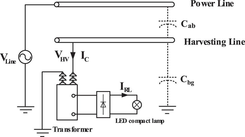
This proposed electric field energy harvester is shown in Figure 1. The harvester, made from an aluminum conductor, was placed in parallel between the medium voltage transmission line, or bus bar, and the ground. The conductor was surrounded by an electric field induced by the transmission line. When the inductive electric charges collect on the surface of the harvester due to an electrostatic induction effect, there is electric field energy stored in the form of a coupling capacitor C ab between the power line and the conductor. To harvest the electric field energy, a two-winding energy-harvesting transformer (EHT) is also necessary. The primary winding of the EHT is connected between the energy-harvesting conductor and the ground, while the secondary winding of the EHT is connected to the resistive load. The transformer is then deployed in order to the requirements of voltage and power of the load, using impedance conversion characteristics.
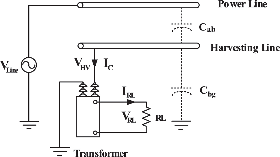
This proposed electric field energy harvester.
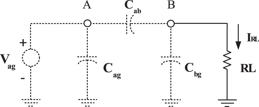
This proposed harvester in Figure 1 can be modeled with the equivalent circuit as shown in Figure 2. The high voltage source V Line in Figure 1 or V ag in Figure 2 and transmission line capacitive coupling to ground (C ag ) are provided on the left side of the schematic, while the harvesting capacitor to ground (C bg ) and the load resistance R L are put on the right side. Both sides are connected by the harvesting capacitor, which causes the capacitive coupling between the power line and the harvesting line. This mutual capacitance C ab is related to distance between the power line and the harvesting line and their sizes.

Equivalent circuit of this proposed harvester without load.
The capacitor C ab represents the primary capacitive coupling between the power line and the harvesting line carrying a medium voltage AC signal. C ab serves as the driving source for an alternating electric field on the surface of harvesting line and can be stated as.
Where l is the length of the harvester, and D is the distance between the power line with a radius of r a and the harvester with a radius of r b. Here, the permittivity e is 8.85 × 10⁻¹² F/m. The parasitic capacitor, C bg , between the harvester line and ground with height h can be calculated by
The voltage V bg induced in the harvester line due to a voltage V ag being applied to the power line V line can be founded by.
The induced current caused by electric-field induction is possibly supplied to the load because it is not resisted by the effective resistance of the load. This scenario can be explained by the circuit diagram shown in Figure 3 when the coupling capacitor between the power line and the harvesting line is very small compared with the load. Thus, the current flowing through the load for this scenario is.
The equivalent circuit connected to load.
The value of C ab is calculated in tens of picofarads. Therefore, this equation is valid for typical values of load (kΩ). C ab , ω, and V ag depend on the system, if it is assumed that these system values (C ab , ω, and V ag ) are not varied. This electric filed energy harvesting system basically acts like a current source within the bounds of the above assumptions.
4 The validation of this concept at medium voltage
To validate the idea of an electric field energy harvester using a parallel line, the experimental is set up as shown in Figure 4. The harvesting line with a 1.28-cm radius is placed under the medium voltage bus bar with a 1.28-cm radius and a 5-m length at a distance of 1 m for safety clearance. The harvesting line gets charged by the displacement current. The induced voltage with no load on the harvesting line is measured with a 5-kV source voltage on the bus bar. The measured induced voltage on the harvesting line of 1 m in length is compared with the calculated induced voltage as shown in Figure 5. The calculated value is greater than the measured value due to transformer characteristic parameters and coil saturation in higher voltages.

The actual experimental setup to validate the idea of this proposed harvester.

The comparison result between the measured induced voltage on the harvesting line and the calculated one.
Finite-element analysis (COMSOL) is used to compute an accurate electric field from a power line with 66.40 kV at 3 m above the ground. Figure 6 illustrated the comparison of the results of the measured and calculated electric field distributions from the power line at the red dot which is potentially located at 4.2-m horizontal axis and 1-m vertical axis. As shown in Figure 6, the value measured with the electric field meter is 1811 V/m, while the simulated value at the red dot is 2157 V/m. The electric field becomes stronger inside of the power line, whereas an entirely weaker electric field, the so-called coupling electric field, is distributed everywhere outside of the power line. The result shows that the simulated electric field is slightly larger than the measured one, probably due to a different environment and the slight difference in the properties of the conductor’s materials.

The simulation of the electric field distribution from power line 66.4 kV compared with the measured value.
When the load level is varied, the induced voltage on the harvesting line is measured for every increment of 5 kV in the power line voltage. The results of the measured induced voltage with load variation are shown in Figure 7. Due to the loading effect, the induced voltage on load increases with more load resistance.

The induced voltage on the harvesting line with load variation and asset power line voltage.
When the current of the harvesting line is measured with the load variation, the result is shown in Figure 8. The result shows that the energy harvester with an electric field was obtained from the constant current source with unchanged system parameters (C ab , ω, and V ag).

The current on the harvesting line with load variation.
The harvested power with load variation can also be shown in Figure 9. It is observed that the harvested power greatly increases with an increase in power line voltage, as it follows a squared relationship. Similarly, the harvested power on the load varies with the changed load values. Moreover, with a further increase in power line voltage level, the harvested power increases.

The harvested power on the harvesting power when the load was changed.
As the harvesting line is placed parallel to the power line, its size should be as large as possible. To validate these, the complementary experiments are set up to vary the sizes of the harvesting line and the distance between the power line and the harvesting line. The result of the induced current on the harvesting line of different sizes and at the distances of 1 m, 1.25 m, and 1.5 m from the power line, is shown in Figure 10. Similarly, the harvesting power due to different sizes of harvesting lines and various distances from the power line is given in Figure 11.

The result of the induced current on harvesting line with both different sizes and distances from power line at 1 m, 1.25 m, and 1.5 m, respectively.
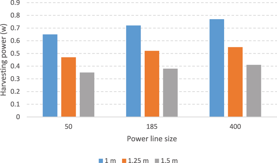
The result of the power on harvesting line with both different sizes and distances from power line at 1 m, 1.25 m, and 1.5 m, respectively.
Let
If R L is the load resistance, the gathered power from the harvesting line can be calculated as
To maximize the output power, therefore
Where the maximum harvested power is therefore found by replacing R L by (9) in (10), i.e. P max = P (Z′ Lopt), as
From the equation (10), the maximum harvesting power depends on the power ling voltage Vag and the coupling capacitor between the power line and harvesting line. However, the harvested power has a convex line for load impedance
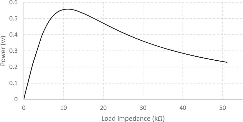
Shows harvesting power on harvesting line at different load levels.
The experimental results confirm the concept of an electric field energy harvester using a parallel line. The maximum harvesting power of this proposed system is close to 0.5 W/m, which may be sufficient to deliver an appropriate power supply to the monitoring devices of the transmission line. Here, the optimal load impedance is approximately 11 kΩ, which includes the excitation inductance, leakage inductance, and core resistance of the transformer paralleled to the load resistance.
5 Implementation of this proposed energy harvesting system
In order to demonstrate the practical effectiveness of this electric field harvesting system using parallel lines, we set up a power supply circuit using this proposed system for an LED compact lamp at a transmission tower as shown in Figure 13. The power line voltage was set at 67 kV compared to the ground. The harvesting line, with a length of 20 m, was installed in parallel with the power line at a distance of 1.2 m, in accordance with the Occupational Safety and Health Administration (OSHA) and Electrical Safety Code. A voltage transformer (VT) formed the primary side of the harvesting line and the ground, while the AC/DC converter connected to the 5 W LED compact lamp formed the secondary side. The specification of the voltage transformer used here was 33 kV/230 V, 1000 VA (Figure 13).
The implementation of this proposed energy harvesting system.
Since the actual area for the implemented system is limited, the harvesting line was laid in a U shape, as shown in Figure 14. The single and dual harvesting lines were verified to improve the harvesting performance. It can be realized that the bundle configuration does not affect the energy harvesting.

The actual test setup for the implementation.
During the verified experiment, the power line voltage was varied from 5 to 67 kV. The harvesting power of the single harvesting line for 500 Ω and 1 kΩ load resistance is shown in Figure 15(a). Similarly, one of the dual harvesting lines is shown in Figure 15(b). It can be seen that the power line voltage at approximately 70 kV, nearly 5 W of power for a single line was derived. In comparison, the harvesting power for dual lines was 5.81 W for 500 Ω load resistance and 6.88 w for 1 kΩ load resistance. Due to the limited space we had for the harvesting line arrangement, increasing the number of harvesting lines in our work does not affect the amount of obtainable power.

The harvesting power of the harvesting line for 500 Ω, 1 kΩ load resistance, (a) single harvesting line, (b) dual harvesting line.
From the experimental result in Figure 15, for a power line voltage of nearly 70 kV, the effective harvesting power is sufficient to drive the 5 W LED compact lamp. The demonstration of this proposed harvesting prototype supplying the 5 W LED compact lamp is realized in Figure 16. Here, the harvesting voltage to supply the LED lamp is 11.78 V and the induced current is 274.4 mA. It is observed that the 5 W LED compact lamp is very bright and it still has the capability to provide the remaining power to drive the red LED in the AC/DC converter circuit.

Shows the result of this proposed energy harvester for 5 W LED compact lamp driving capability.
In monitoring a transmission line or a power line, various sensor nodes working together wirelessly as a network are needed. In such sensor nodes, an electronic embedded system is one of its important components. Typically, the electronics inside an embedded electronic system consume a lot of energy. The estimation of commercial processor energy consumption is shown in Table 1.
Estimation of commercial processor peak power.
| Device | Peak power estimation (mW) |
|---|---|
| MSP430F2274 | 9.504 |
| FM32TG840F32 | 14.4 |
| ATMega128RFA1 | 66.96 |
| JN5148-001 | 127.08 |
| MC1322x | 79.2 |
From Table 1, we can see that the processors in the sensor node mostly require power in the range of ten to a hundred mW. This energy requirement is well within the capability of our proposed energy harvesting system. Thus, our proposed energy harvester is more than adequate in supplying any sensor node used in these transmission line or power line monitoring purposes.
6 Conclusions
This paper presents a novel battery-free electric field energy harvesting from the power line. The energy is harvested from the medium or high voltage alternating electric field which provides a displacement current flowing through the harvesting line. This can work as a constant current source to supply the load. The harvesting power is proportional to the displacement current and the induced voltage between the power line and the harvesting line. The results from the validation of this proposed energy harvester shows that, depending on the length and size of the harvesting line, the highest obtainable power is at the watt level. The practical implementation was demonstrated to prove the performance of this proposed energy harvester. The AC induced voltage of this harvester is converted to a DC voltage with the rectifier and is successfully driving the DC load. Experimental results indicate a continuous power of approximately 5–6 W at 70 kV bus voltage. This power is enough to drive the 5 W LED compact lamp attached to an MV/HV asset. This proposed energy harvesting system is also simple to install on the transmission line, making it more widely applicable and easier and safer to deploy. A typical energy-harvesting ability of W and mA level was achieved. This is adequate for typical monitoring devices, with the potential of achieving even higher power output depending on the length and size of the harvesting line, and the distance between the power line and the harvesting line. The proposed system can consistently supply energy to monitoring sensors of a transmission line, hence eliminating the need of frequent battery replacements. In the future, the influence of voltage transformer parameters should also be investigated, along with a variety of weather conditions, such as humidity in the rainy season which may cause corona and partial discharge, and subsequently damage the monitoring devices. However, a follow-on power electronic converter is necessary to experimentally achieve these circumstances. The optimum circuit design for this conversion technique under the operating restrictions outlined in this paper will be the subject of future research.
-
Author contributions: All the authors have accepted responsibility for the entire content of this submitted manuscript and approved submission.
-
Research funding: This work was supported by the human development in the Province of Electricity Authority, cooperating with the Faculty of Engineering, Prince of Songkla University, Thailand under MOU. The authors also would like to thank the anonymous reviewers for their valuable comments.
-
Conflict of interest statement: The authors declare no conflicts of interest regarding this article.
References
Ahmad, I., L. M. Hee, A. M. Abdelrhman, S. A. Imam, and M. Leong. 2021. “Challenges and Approaches of Energy Harvesting for Wireless Sensor Nodes in Machine Condition Monitoring Systems: A review,” Measurement 183: 109856. https://doi.org/10.1016/j.measurement.2021.109856.Search in Google Scholar
Bogue, R. 2013. “Sensors for Condition Monitoring: A Review of Technologies and Applications.” Sensor Review 33 (4): 295–9. https://doi.org/10.1108/sr-05-2013-675.Search in Google Scholar
Bunnoon, P., T. Thongyoo, and C. Wanden. 2020. “Right-of-Way Monitoring Camera Storage Energy Around High Voltage Power Transmission Using Hybrid Energy Harvesting-Mfield, Efield to Super Capacitor Batteries Back-Up Charger.” Journal of Electrical Engineering & Technology 15 (2): 611–20. https://doi.org/10.1007/s42835-020-00354-4.Search in Google Scholar
Chen, J., J. Klein, Y. Wu, S. Xing, R. Flammang, M. Heibel, and L. Zuo. 2016. “A Thermoelectric Energy Harvesting System for Powering Wireless Sensors in Nuclear Power Plants.” IEEE Transactions on Nuclear Science 63 (5): 2738–46. https://doi.org/10.1109/tns.2016.2606090.Search in Google Scholar
Fadhlullah, S. Y., and W. Ismail. 2015. “Solar Energy Harvesting Design Framework for 3.3 V Small and Low-Powered Devices in Wireless Sensor Network.” In Telematics and Future Generation Networks (TAFGEN).10.1109/TAFGEN.2015.7289583Search in Google Scholar
Kadechkar, A., J. Sanllehi, M. Moreno-Eauilaz, and J. R. Riba. 2018. “Feasibility Analysis of Bluetooth 5 for Real-Time Data Transmission in High-Voltage AC and DC Substations.” In Proc. 44th Annu. Conf. IEEE Ind. Electron. Soc. (IECON), 5228–33.10.1109/IECON.2018.8595406Search in Google Scholar
Kang, S., J. Kim, S. Yang, T. Yun, and H. Kim. 2017. “Electric Field Energy Harvesting under Actual Three-phase 765 kV Power Transmission Lines for Wireless Sensor Node.” Electronics Letters 53 (16): 1135–6. https://doi.org/10.1049/el.2017.1794.Search in Google Scholar
Khawaja, A. H., Q. Huang, and Z. H. Khan. 2017. “Monitoring of Overhead Transmission Lines: A Review from the Perspective of Contactless Technologies.” Sensing and Imaging 18 (1): 18–24. https://doi.org/10.1007/s11220-017-0172-9.Search in Google Scholar
Li, X., Q. Gao, Y. Cao, Y. Yang, S. Liu, Z. L. Wang, and T. Cheng. 2022. “Optimization Strategy of Wind Energy Harvesting via Triboelectric-Electromagnetic Flexible Cooperation.” Applied Energy 307: 118311. https://doi.org/10.1016/j.apenergy.2021.118311.Search in Google Scholar
Liao, X., Y. Liu, J. Ren, L. Guan, X. Sang, B. Wang, H. Zhang, Q. Wang, and T. Ma. 2020. “Investigation of a Double-PCM-Based Thermoelectric Energy-Harvesting Device Using Temperature Fluctuations in an Ambient Environment.” Energy 202: 117724. https://doi.org/10.1016/j.energy.2020.117724.Search in Google Scholar
Liu, X., C. Li, Y. D. Deng, and C. Q. Su. 2015. “An Energy-Harvesting System Using Thermoelectric Power Generation for Automotive Application.” International Journal of Electrical Power & Energy Systems 67: 510–6. https://doi.org/10.1016/j.ijepes.2014.12.045.Search in Google Scholar
Liu, Y., X. Xie, Y. Hu, Y. Qian, G. Sheng, and X. Jiang. 2016. “A Novel High-Density Power Energy Harvesting Methodology for Transmission Line Online Monitoring Devices.” Review of Scientific Instruments 87 (7): 1–8, https://doi.org/10.1063/1.4959556.Search in Google Scholar PubMed
Mekikis, P., E. Kartsakli, A. Antonopoulos, L. Alonso, and C. Verikoukis. 2018. “Connectivity Analysis in Clustered Wireless Sensor Networks Powered by Solar Energy.” IEEE Transactions on Wireless Communications 1276: 2389–401, https://doi.org/10.1109/twc.2018.2794963.Search in Google Scholar
Moghe, R., A. Iyer, F. C. Lambert, and D. Divan. 2015. “A Low-Cost Electric Field Energy Harvester for an MV/HV Asset-Monitoring Smart Sensor.” IEEE Transactions on Industry Applications 51 (2): 1828–36. https://doi.org/10.1109/tia.2014.2354741.Search in Google Scholar
Nurmanova, V., M. Bagheri, T. Phung, and S. K. Panda. 2018. “Feasibility Study on Wind Energy Harvesting System Implementation in Moving Trains.” Electrical Engineer 100 (3): 1837–45. https://doi.org/10.1007/s00202-017-0664-6.Search in Google Scholar
Pan, H., H. Li, T. Zhang, A. A. Laghari, Z. Zhang, Y. Yuan, and B. Qian. 2019. “A Portable Renewable Wind Energy Harvesting System Integrated S-Rotorand H-Rotor for Self-Powered Applications in High-Speed Railway Tunnels.” Energy Conversion and Management 196: 56–68. https://doi.org/10.1016/j.enconman.2019.05.115.Search in Google Scholar
Preeprem, S., Executive staff. 2021. The Annual Report of the Province Electricity Authority (PEA) of Thailand. Thailand: PEA.Search in Google Scholar
Rodriguez, J. C., D. G. Holmes, B. P. McGrath, and R. H. Wilkinson. 2014. “Maximum Energy Harvesting from Medium Voltage Electric-Field Energy Using Power Line Insulators.” In Proc. IEEE Australasian Universities Power Engineering Conf., 1–6. IEEE.10.1109/AUPEC.2014.6966633Search in Google Scholar
Roscoe, N. M., and M. D. Judd. 2013. “Harvesting Energy from Magnetic Fields to Power Condition Monitoring Sensors.” IEEE Sensors Journal 13 (6): 2263–70. https://doi.org/10.1109/jsen.2013.2251625.Search in Google Scholar
Sanda, M., T. Kojima, E. Higashi, T. Maruyama, N. Iwama, and O. Saka. 2018. “Overhead Transmission Line Monitoring System for Dynamic Rating.” SEI Technical Review 87: 64–9.Search in Google Scholar
Santos, J. D., M. Salleras, I. Donmez, G. Gadea, C. Calaza, À. Morata, A. Tarancón, and L. Fonseca. 2016. “Power Response of a Planar Thermoelectric Microgenerator Based on Silicon Nanowires at Different Convection Regimes.” Energy Harvesting and Systems 3 (4): 335–42. https://doi.org/10.1515/ehs-2016-0019.Search in Google Scholar
Singh, J., P. Kuchroo, and H. Bhatia. 2016. “Floating TEG Based Solar Energy Harvesting System.” In Automatic Control and Dynamic Optimization Techniques (ICACDOT).10.1109/ICACDOT.2016.7877689Search in Google Scholar
Wang, W., Z. Zhu, Q. Wang, and M. Hu. 2019. “Optimisation Design of Realtime Wireless Power Supply System Overhead High-Voltage Power Line.” IET Electric Power Applications 13 (2): 206–14. https://doi.org/10.1049/iet-epa.2018.5498.Search in Google Scholar
Wen, Q., X. He, Zh. Lu, R. Streiter, and Th. Otto. 2021. “A Comprehensive Review of Miniatured Wind Energy Harvesters.” Nano Materials Science 3: 170–85. https://doi.org/10.1016/j.nanoms.2021.04.001.Search in Google Scholar
White, R., D. S. Nguyen, Z. Wu, and P. Wright. 2018. “Atmospheric Sensors and Energy Harvesters on Overhead Power Lines.” Sensors 18 (2): 114. https://doi.org/10.3390/s18010114.Search in Google Scholar PubMed PubMed Central
Wu, Z. Y., Y. M. Wen, and P. Li. 2013. “A Power Supply of Self-Powered Online Monitoring System for Power Cords.” IEEE Transactions on Energy Conversion 28 (4): 921–8. https://doi.org/10.1109/tec.2013.2281075.Search in Google Scholar
Yuan, S., Y. Huang, J. Zhou, Q. Xu, C. Song, and P. Thompson. 2015. “Magnetic Field Energy Harvesting under Overhead Power Lines.” IEEE Transactions on Power Electronics 30 (11): 6191–202, Nov. https://doi.org/10.1109/tpel.2015.2436702.Search in Google Scholar
Zangl, H., T. Bretterklieber, and G. Brasseur. 2009. “A Feasibility Study on Autonomous Online Condition Monitoring of High-Voltage Overhead Power Lines.” IEEE Transactions on Instrumentation and Measurement 58 (5): 1789–96. https://doi.org/10.1109/tim.2009.2012943.Search in Google Scholar
Zeng, X., Z. Yang, P. Wu, L. Cao, and Y. Luo. 2021. “Power Source Based on Electric Field Energy Harvesting for Monitoring Devices of High Voltage Transmission Line.” IEEE Transactions on Industrial Electronics 68 (8): 7083–92. https://doi.org/10.1109/tie.2020.3003551.Search in Google Scholar
Zhao, X., T. Keutel, M. Baldauf, and O. Kanoun. 2013. “Energy Harvesting for a Wireless-Monitoring System of Overhead High-Voltage Power Lines.” IET Generation, Transmission & Distribution 7 (2): 101–7. https://doi.org/10.1049/iet-gtd.2012.0152.Search in Google Scholar
Zhao, D., D. Dai, and L. Li. 2015. “Electric Field Energy Harvesting for On-Line Condition-Monitoring Device Installed on High-Voltage Transmission Tower.” Electronics Letters 51 (21): 1692–3. https://doi.org/10.1049/el.2015.1975.Search in Google Scholar
Zhao, L., and Y. Yang. 2017. “Toward Small-Scale Wind Energy Harvesting: Design Enhancement Performance Comparison and Applicability.” Shock and Vibration 2017: 1–31. https://doi.org/10.1155/2017/3585972.Search in Google Scholar
Zhuang, Y., C. Xu, C. Song, A. Chen, W. L. Y. Huang, and J. Zhou. 2020. “Improving Current Transformer-Based Energy Extraction from AC Power Lines by Manipulating Magnetic Field.” IEEE Transactions on Industrial Electronics 67 (11): 9471–9. https://doi.org/10.1109/tie.2019.2952795.Search in Google Scholar
© 2024 the author(s), published by De Gruyter, Berlin/Boston
This work is licensed under the Creative Commons Attribution 4.0 International License.
Articles in the same Issue
- Solar photovoltaic-integrated energy storage system with a power electronic interface for operating a brushless DC drive-coupled agricultural load
- Analysis of 1-year energy data of a 5 kW and a 122 kW rooftop photovoltaic installation in Dhaka
- Reviews
- Real yields and PVSYST simulations: comparative analysis based on four photovoltaic installations at Ibn Tofail University
- A comprehensive approach of evolving electric vehicles (EVs) to attribute “green self-generation” – a review
- Exploring the piezoelectric porous polymers for energy harvesting: a review
- A strategic review: the role of commercially available tools for planning, modelling, optimization, and performance measurement of photovoltaic systems
- Comparative assessment of high gain boost converters for renewable energy sources and electrical vehicle applications
- A review of green hydrogen production based on solar energy; techniques and methods
- A review of green hydrogen production by renewable resources
- A review of hydrogen production from bio-energy, technologies and assessments
- A systematic review of recent developments in IoT-based demand side management for PV power generation
- Research Articles
- Hybrid optimization strategy for water cooling system: enhancement of photovoltaic panels performance
- Solar energy harvesting-based built-in backpack charger
- A power source for E-devices based on green energy
- Theoretical and experimental investigation of electricity generation through footstep tiles
- Experimental investigations on heat transfer enhancement in a double pipe heat exchanger using hybrid nanofluids
- Comparative energy and exergy analysis of a CPV/T system based on linear Fresnel reflectors
- Investigating the effect of green composite back sheet materials on solar panel output voltage harvesting for better sustainable energy performance
- Electrical and thermal modeling of battery cell grouping for analyzing battery pack efficiency and temperature
- Intelligent techno-economical optimization with demand side management in microgrid using improved sandpiper optimization algorithm
- Investigation of KAPTON–PDMS triboelectric nanogenerator considering the edge-effect capacitor
- Design of a novel hybrid soft computing model for passive components selection in multiple load Zeta converter topologies of solar PV energy system
- A novel mechatronic absorber of vibration energy in the chimney
- An IoT-based intelligent smart energy monitoring system for solar PV power generation
- Large-scale green hydrogen production using alkaline water electrolysis based on seasonal solar radiation
- Evaluation of performances in DI Diesel engine with different split injection timings
- Optimized power flow management based on Harris Hawks optimization for an islanded DC microgrid
- Experimental investigation of heat transfer characteristics for a shell and tube heat exchanger
- Fuzzy induced controller for optimal power quality improvement with PVA connected UPQC
- Impact of using a predictive neural network of multi-term zenith angle function on energy management of solar-harvesting sensor nodes
- An analytical study of wireless power transmission system with metamaterials
- Hydrogen energy horizon: balancing opportunities and challenges
- Development of renewable energy-based power system for the irrigation support: case studies
- Maximum power point tracking techniques using improved incremental conductance and particle swarm optimizer for solar power generation systems
- Experimental and numerical study on energy harvesting performance thermoelectric generator applied to a screw compressor
- Study on the effectiveness of a solar cell with a holographic concentrator
- Non-transient optimum design of nonlinear electromagnetic vibration-based energy harvester using homotopy perturbation method
- Industrial gas turbine performance prediction and improvement – a case study
- An electric-field high energy harvester from medium or high voltage power line with parallel line
- FPGA based telecommand system for balloon-borne scientific payloads
- Improved design of advanced controller for a step up converter used in photovoltaic system
- Techno-economic assessment of battery storage with photovoltaics for maximum self-consumption
- Analysis of 1-year energy data of a 5 kW and a 122 kW rooftop photovoltaic installation in Dhaka
- Shading impact on the electricity generated by a photovoltaic installation using “Solar Shadow-Mask”
- Investigations on the performance of bottle blade overshot water wheel in very low head resources for pico hydropower
- Solar photovoltaic-integrated energy storage system with a power electronic interface for operating a brushless DC drive-coupled agricultural load
- Numerical investigation of smart material-based structures for vibration energy-harvesting applications
- A system-level study of indoor light energy harvesting integrating commercially available power management circuitry
- Enhancing the wireless power transfer system performance and output voltage of electric scooters
- Harvesting energy from a soldier's gait using the piezoelectric effect
- Study of technical means for heat generation, its application, flow control, and conversion of other types of energy into thermal energy
- Theoretical analysis of piezoceramic ultrasonic energy harvester applicable in biomedical implanted devices
- Corrigendum
- Corrigendum to: A numerical investigation of optimum angles for solar energy receivers in the eastern part of Algeria
- Special Issue: Recent Trends in Renewable Energy Conversion and Storage Materials for Hybrid Transportation Systems
- Typical fault prediction method for wind turbines based on an improved stacked autoencoder network
- Power data integrity verification method based on chameleon authentication tree algorithm and missing tendency value
- Fault diagnosis of automobile drive based on a novel deep neural network
- Research on the development and intelligent application of power environmental protection platform based on big data
- Diffusion induced thermal effect and stress in layered Li(Ni0.6Mn0.2Co0.2)O2 cathode materials for button lithium-ion battery electrode plates
- Improving power plant technology to increase energy efficiency of autonomous consumers using geothermal sources
- Energy-saving analysis of desalination equipment based on a machine-learning sequence modeling