Numerical investigation of smart material-based structures for vibration energy-harvesting applications
-
Atul


Abstract
The present work deals with energy-harvesting devices, which are useful in scavenging power using piezoelectric materials. Utilizing classical beam theory and classical plate theory, finite element modelling has been carried out to optimize the performance of output power of a cantilever beam and a flexible rectangular plate. Harmonic oscillations and base excitation will be the two different forcing functions used to drive the system. Based on this, numerical investigations of the performance of output power for the piezoelectric cantilever beam and flexible rectangular plate with different cases are considered. The present work is also useful for designing the piezoelectric cantilever beams and plates to extract maximum output power within the frequency ranges from 0 to 200 Hz. Numerical investigations on the piezoelectric cantilever beam and flexible rectangular plate with different cases reveal that the performance of output power is influenced by factors like load resistance, applications of with and without host structures, and different design parameters like unimorph, bimorph, embedded, line- and cross-type piezoelectric patch arrangements.
1 Introduction
Energy-harvesting technology creates autonomous, self-powered electronic systems that do not rely on battery power for their operation (Johnson et al. 2006). The term energy harvesting describes the process of converting ambient energy surrounding a system into useful electrical energy using a specific material or transducer. A widely studied form of energy harvesting involves the conversion of mechanical vibration energy into electrical energy using piezoelectric materials, which exhibit electromechanical coupling between the electrical and mechanical domains (Ng and Liao 2004, 2005, Jiang et al. 2005). Typical piezoelectric energy-harvesting systems are designed as add-on systems to a host structure located in a rich vibration environment (Anderson and Sexton 2006).
The energy requirements of low-power electronics have steadily decreased with advancements in efficient circuitry such that energy-harvesting systems can be considered feasible solutions in providing power to self-powered systems. Conventional low-power electronics, such as wireless sensor nodes, rely on batteries to provide power to the device. The use of batteries, however, presents several drawbacks, including the cost of battery replacement as well as limitations imposed by the need for convenient access to the device for battery replacement purposes (Mateu and Moll 2005). Besides, the disadvantages of batteries also include a finite amount of energy or limited time span, large maintenance requirements, very high mass-to-electrical power ratio, and possible hazardous chemicals and environmental effects. The limited time span of a battery makes a device not so reliable because it may stop working at any time without notice due to the sudden death of the battery (Roundy et al. 2005). The dead battery must be replaced by a tedious and expensive task, especially when the device is in a remote location. Wireless sensor nodes, for example, are often used in remote locations or embedded into a structure; therefore, access to the device can be difficult or impossible. By scavenging ambient energy surrounding an electronic device, energy-harvesting solutions can provide permanent power sources that do not require periodic replacement. Such systems can operate in an autonomous, self-powered manner, reducing the costs associated with battery replacement, and can easily be placed in remote locations or embedded into host structures (Baker et al. 2005, Kim et al. 2004). Thus, powering devices require a size that is compatible with the application, sufficient power, and extended lifetime using permanent and ubiquitous energy sources (Shahruz 2006). Different arrangements of piezo patches are also encountered for the vibration suppression behaviour of flexible plates (Atul and Deepak 2022). Computational simulation is done to find 31 effects of the piezo cantilever beam for sensor applications (Atul et al. 2014).
2 Objectives and scope of work
With piezoceramic materials, it is possible to harvest power from vibrating structures. It has been proven that microwatts of power can be generated from vibrating systems within frequency ranges from 0 to 200 Hz. The vibration sources for the given frequency ranges are available in our day-to-day lives. We develop finite element models to predict the power generated from a cantilever beam and cantilever plate. Harmonic oscillations and base excitation will be the two different forcing functions used to drive the system. The finite element models are validated by comparing them with published data. A parametric study is also performed to optimize the performance of the output power of a cantilever beam plate. The primary objectives of the present work are the following:
Finite element modelling and analysis of output power of a piezoelectric cantilever beam and plate using classical beam theory and classical plate theory, respectively.
To examine the performance of output power of a piezoelectric cantilever beam with host structure with different cases for unimorph, bimorph, and embedded piezoelectric beam.
To examine the performance of output power of a piezoelectric cantilever plate with line- and cross-type piezoelectric patch arrangement with different cases of unimorph, bimorph, and embedded piezoelectric plates.
This proposed work describes the numerical investigations of the performance of output power for the piezoelectric cantilever beams and plates, considering different cases. The numerical investigation is also useful for designing the piezoelectric cantilever beams and plates to extract maximum output power in the frequency range of 0–200 Hz.
3 Numerical methodology
A piezoelectric cantilever beam is modelled under the assumption of classical beam theory that describes the kinematics of thin beams (beams for which the ratio of length to the in-plane thickness L/b > 10). This theory assumes that the area of the cross-section is rigid in its own plane. So, no deformation of the cross-section occurs in its plane, and the cross-section remains normal to the deformed axis of the beam. The axial displacement can be written in terms of rigid body translation and rotation as
where
The strains developed in the beam can be found using the kinematic quantities defined in equations (1)–(3). Now, a generalized Hamilton’s principle is employed for predicting the electrical output power of cantilevered Euler–Bernoulli beams in energy harvesting:
where T is the total kinetic energy, U is the total potential energy, and W e is the electrical energy.
A piezoelectric beam in a series connection is considered. Electrodes are placed on top and bottom of the piezo strips, and they are assumed to be perfectly conductive so that a uniform electric field exists across them. A resistor R is connected across the beam. In the series connection, the two piezoelectric layers have opposite polarization directions, and an electric field is applied across the total thickness of the bimorph.
The width and thickness of the piezoelectric cantilever beam are very small compared to its length. For that reason, the components of σ 2 and σ 3 of the stress tensor are very small and they can be neglected. Thus, the linear constitutive relations can be simplified as
Equations (5) and (6) represent the piezoelectric constitutive relations for the series connection. Using the constitutive relations again, the generalized Hamilton’s principle is solved.
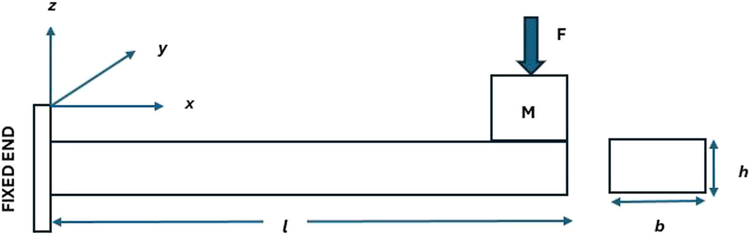
The element shown in Figure 1 has two nodes with three degrees of freedom (DOF). Three mechanical DOF (u, w, θ), the axial nodal, transverse nodal displacements, and the rotation angle, respectively, are defined at each node. The finite element discretization is done with the help of ANSYS. The displacement DOF is constrained to be zero for the fixed end of the cantilever beam. After discretization based on Hamilton’s principle, the element matrix [m], stiffness matrix [k], electromechanical coupling matrix [θ], and capacitance c p are calculated for a single element.
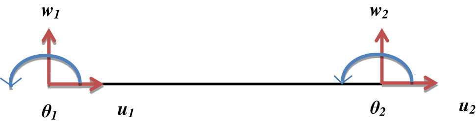
Two- node Euler–Bernoulli elements.
Thus, assembling the element matrices given for a single element, the global equations of motion are then obtained as
where M is the global mass matrix, K is the global stiffness matrix, Ʊ is the global electromechanical coupling matrix, c p is the diagonal global capacitance matrix, v 0 is the global vector of voltage outputs, Q is the global vector of electric charge outputs, C is the global damping matrix, and F is the force owing to base excitation.
A resistive load R, added across the piezoceramic layer, results in a current I = dQ/dt in the circuit. Differentiating equation (8), we get
By defining a potential degree of freedom for each element, it is assumed that there are as many electrodes as the number of elements and that these elements are insulated from each other. So, the potential values are not the same. A continuous electrode is placed on top of the piezoceramic layer, and a single potential difference v 0 exists across the thickness of the piezoceramic layer.
The current in the circuit can be expressed using Ohm’s law (I = v 0 /R) as
Now, another case of a piezoelectric cantilever plate is considered and modelled under the assumption of the classical (Kirchhoff) plate theory. According to this theory, the transverse shear strains and rotary inertias of the finite element are neglected, and in-plane displacements (u and v) are assumed to be due to the bending (cross-section rotation) of the plate only. Thus, the displacement field is then given by
where the displacement components u, v, and w at the thickness level z from the reference (neutral) surface are given in terms of the transverse deflection (w) of the reference surface.
The mechanical strain components can be written in terms of displacement components from equation (11):
Based on Hamilton’s principle given by equation (4), the element matrix [m], stiffness matrix [k], electromechanical coupling matrix [θ], capacitance c p, and the mechanical forcing vector [f] are obtained.
The width and thickness of a piezoelectric cantilever plate are not very small compared to its length. For that reason, the components σ 1, σ 2, and σ 3 of the stress tensor are also not very small, and thus they are taken into account. Therefore, the linear constitutive relations can be simplified as
The element shown in Figure 2 has four nodes having three DOF. Three mechanical DOFs (w, θ x , θ y ), which are the transverse nodal displacements and bending rotation angle in the x- and y-axis, respectively, are defined at each node. The finite element discretization is done with the help of ANSYS. The displacement DOFs are constrained to be zero for the fixed end of the cantilever beam. After discretization based on Hamilton’s principle, the element matrix [m], stiffness matrix [k], electromechanical coupling matrix [θ], and capacitance c p are calculated for a single element. Then, assembling the element matrices, the global equations of motion are given by equations (7) and (8).
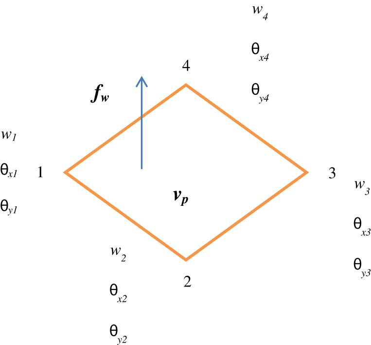
A four-node Kirchhoff’s element.
4 Verifications against the published results
The published results of Ly et al. (2011) have been used for validation. Ly et al. (2011) used a piezoelectric cantilever beam having a rectangular cross-section. The beam is subjected to 0.01 N excitation forces at the free end of the cantilever. The length of the beam is 49 mm with a thickness of 0.6 mm and a width of 3.8 mm. Figures 3–6 show the comparison of the published results with that of the present work using the finite element method. Figures 3 and 4 show the variation of tip displacement and voltage generated with a piezoelectric cantilever beam under an excitation force of 0.01 N at the tip, and the coefficient of damping assumed is 0.05 for the first mode. Similarly, Figures 5 and 6 show the variation of resonant frequencies and voltage generated with different proof masses for the first mode, respectively. Thus, as shown in Figures 3–6, a good agreement was observed between the experiment and present work by using the same methodology as discussed in Section 3.
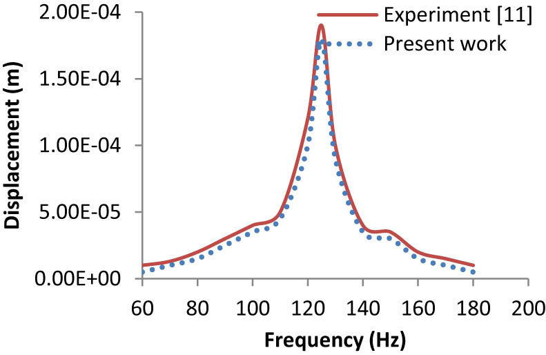
Harmonic response in terms of tip displacement (first mode).
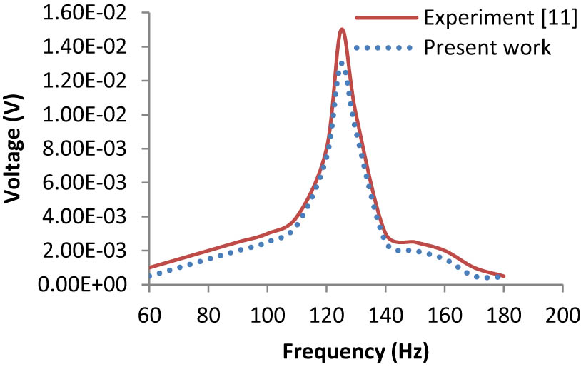
Harmonic response in terms of voltage (first mode).
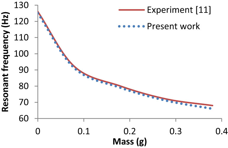
Variation of resonance frequencies with different proof masses (first mode).
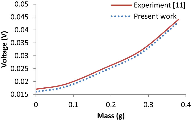
Variation of voltage generated with different proof masses (first mode).
The above agreement is done with the help of ANSYS, which is used as a tool for the finite element method. Based on the same methodology, the results obtained helped us move further with different cases to evaluate the performance of piezoelectric cantilever beams and plates.
5 Results and discussion
5.1 Numerical investigation of the performance of output power for a piezoelectric cantilever beam without a host structure
Under this objective, the numerical investigation of output power for a piezoelectric cantilever beam without a host structure is examined. Figure 7 shows a cantilever beam without any substructure having proof mass at the free end to adjust the resonance frequency.
Schematic piezoelectric cantilever beam without a substructure.
The frequency dependence of the output voltage and power at load resistances of 2.5, 4.5, 6.5, and 10 kΩ are plotted in Figure 8. From the figure, it can be seen that when the load resistance increases, the output peak voltage increases, while the output power first increases, reaches a maximum value at an appropriate load resistance, and then decreases with a further increase of resistance. The maximum value of the output power is about 2.8 μW at a load resistance of 30 kΩ. The maximum output voltage can be obtained by choosing a load resistance that is large enough, but a matching load resistance should be chosen to obtain maximum output power. As shown in Figure 9, the resonance frequency varies from 62 to 66 Hz with the thickness of the piezoelectric layer, and the output peak voltage decreases with an increase of thickness because the piezoelectric layer with a larger thickness weakens the deformation of the cantilever beam. The dependence of the generated voltage can be studied considering the size of the device being used to generate the electrical energy and the stress distribution that is acting on the piezoelectric layer. So, a large output voltage can be obtained by choosing the thinner beam where strain is greater.
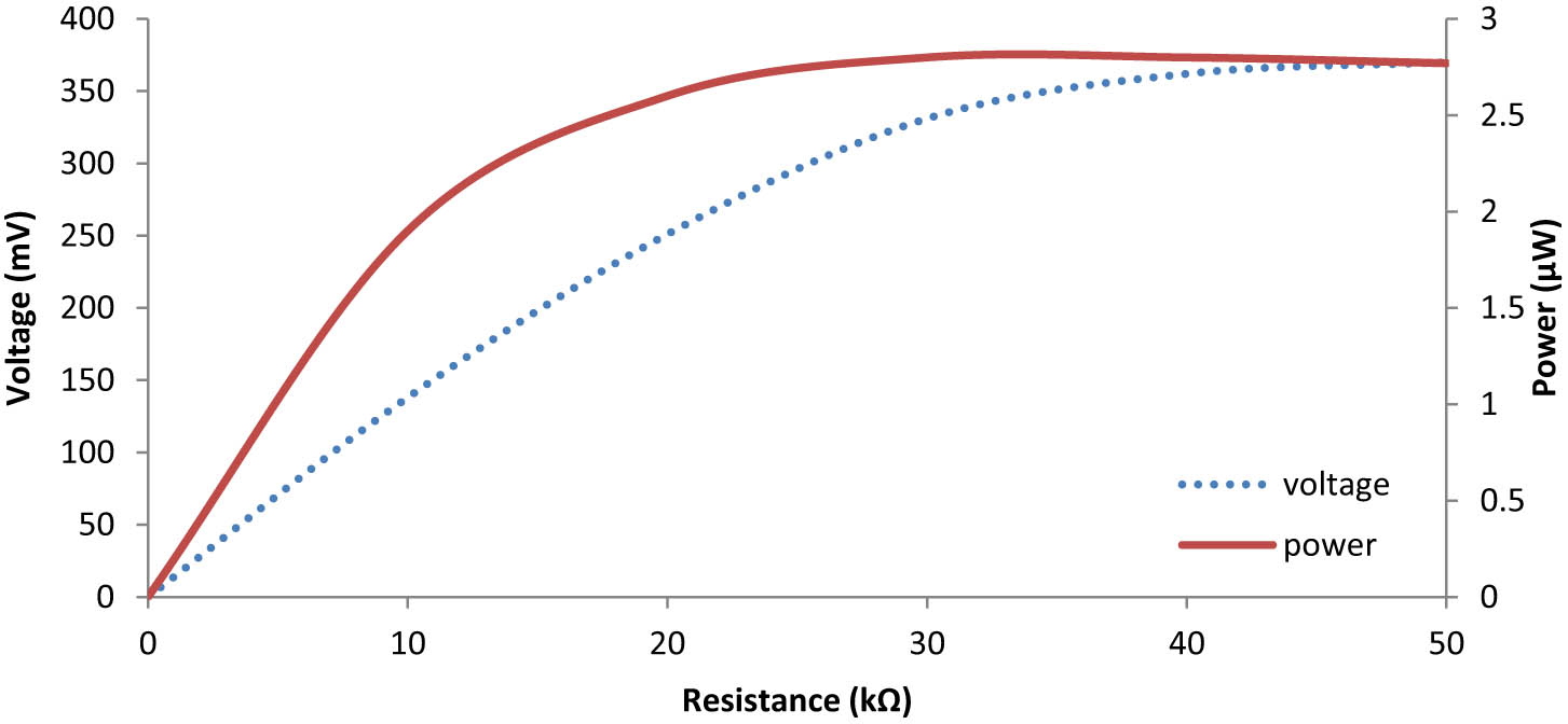
The output peak voltage and output power versus load resistance.
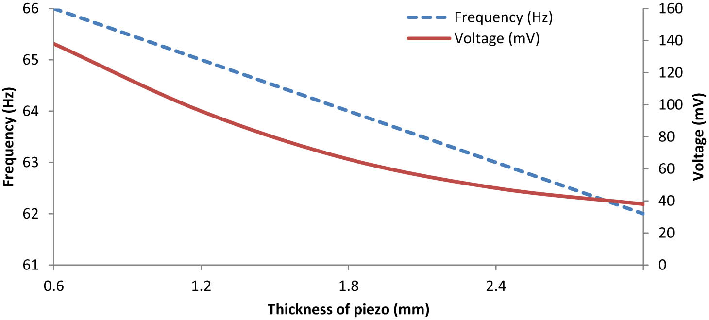
The output peak voltage and resonance frequency versus the thickness of the piezoelectric layer at R = 10 kΩ.
5.2 Numerical investigation of the performance of output power for a piezoelectric cantilever beam with a host structure
Under this objective, three cases, i.e. unimorph, bimorph, and embedded beams, are investigated numerically for their output performance using silicon as a host structure, as shown in Figures 9–11. The masses of unimorph and bimorph cantilever plates remain constant, except for the embedded piezoelectric beam (Figure 12).
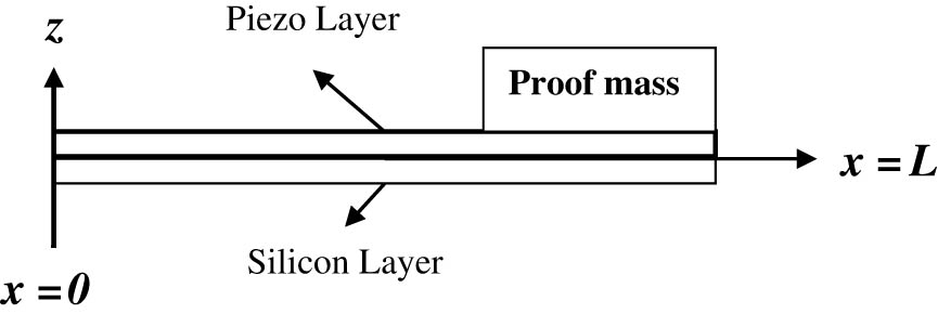
Unimorph piezoelectric cantilever beam.
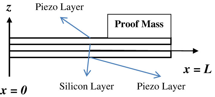
Bimorph piezoelectric cantilever beam.
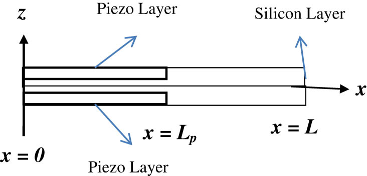
Embedded piezoelectric cantilever beam.
5.2.1 Unimorph
An energy-harvesting cantilever beam with an integrated Si proof mass was designed and numerically evaluated. The maximum power is attained at 6.5 kΩ of optimal resistance load, and the device had 147 mV of peak voltage and 0.42 μW under 0.75 g acceleration force at 162 Hz (Figure 13).
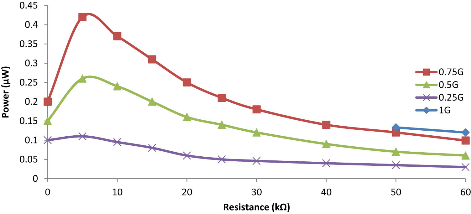
Power versus load resistances at different g values from the unimorph cantilever on Si.
5.2.2 Bimorph
A bimorph piezoelectric energy-harvesting cantilever performance is numerically evaluated. The mass remains constant as that of an unimorph piezoelectric cantilever beam. The resonance frequency at which the bimorph energy harvester shows its performance is quite lower than that of the unimorph energy harvester. Similar monotonic behaviour of voltage output with increasing load resistance is observed for all excitation frequencies according to the results of the numerical finite element model. The maximum power is attained at 10 kΩ of the optimal resistance load, and the device had 98 mV of peak voltage and 0.96 μW under 0.75 g acceleration force at 138 Hz, as shown in Figures 14 and 15.
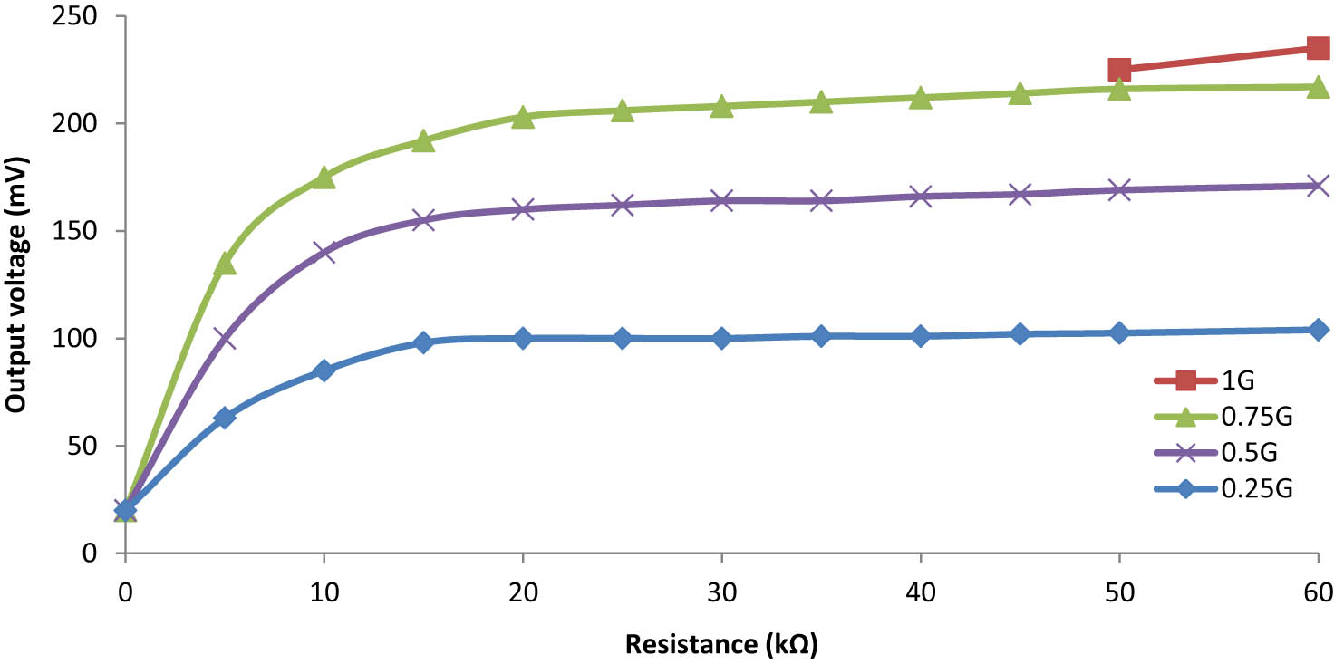
Output peak voltage versus load resistances at different g values for the unimorph cantilever on Si.
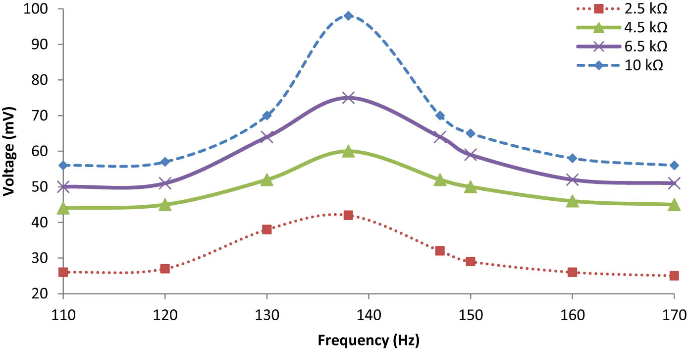
Frequency dependence output voltage for the bimorph energy harvester under 0.75g.
5.2.3 Embedded
From Figure 16, it can be observed that when the load resistance increases, the output voltage increases, but when the load resistance exceeds 10 kΩ, it does not affect the output power of the embedded energy harvester. In this case study, the length and thickness of piezoceramics are kept constant, and the proof is not present at the tip of the beam. The resonance frequency at which the embedded energy harvester shows its performance is good as compared to the previous energy harvester, which is discussed in the above section. The frequency dependence output power is also plotted in Figure 14, which shows that after applying a load resistance greater than 10 kΩ, the output power of the embedded cantilever beam decreases. Various parameters could be altered to analyse this case study. The maximum output power obtained in this case is 2.3 μW under a gravitational acceleration of 0.75 g at 124 Hz with a load resistance of 10 kΩ (Figure 17).
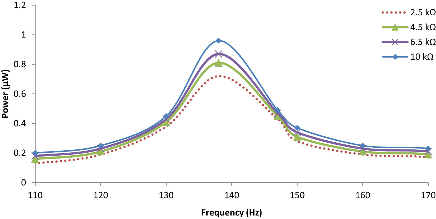
Frequency dependence output power for the bimorph energy harvester under 0.75g.
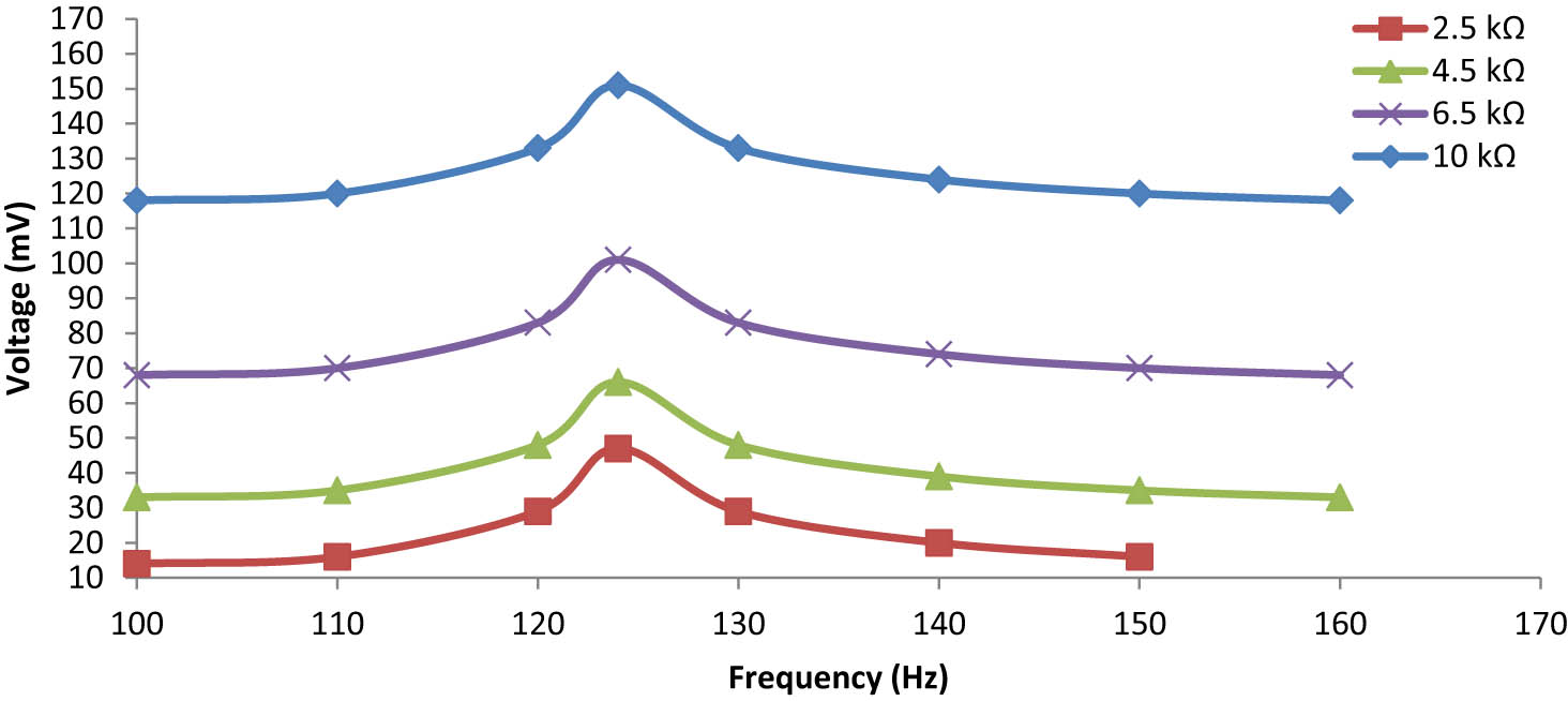
Frequency dependence output voltage of the embedded beam under 0.75 g.
5.3 Numerical investigation of the performance of output power for a piezoelectric cantilever plate with a host structure
Under this objective, three cases, i.e. unimorph, bimorph, and embedded piezoelectric cantilever plates, are investigated numerically for their output performance, where line type and cross piezoelectric patch are imposed on the silicon substructure, as shown in Figures 18 and 19 (top view). The mass remains constant throughout all the cases being considered, except the embedded piezoelectric plate.
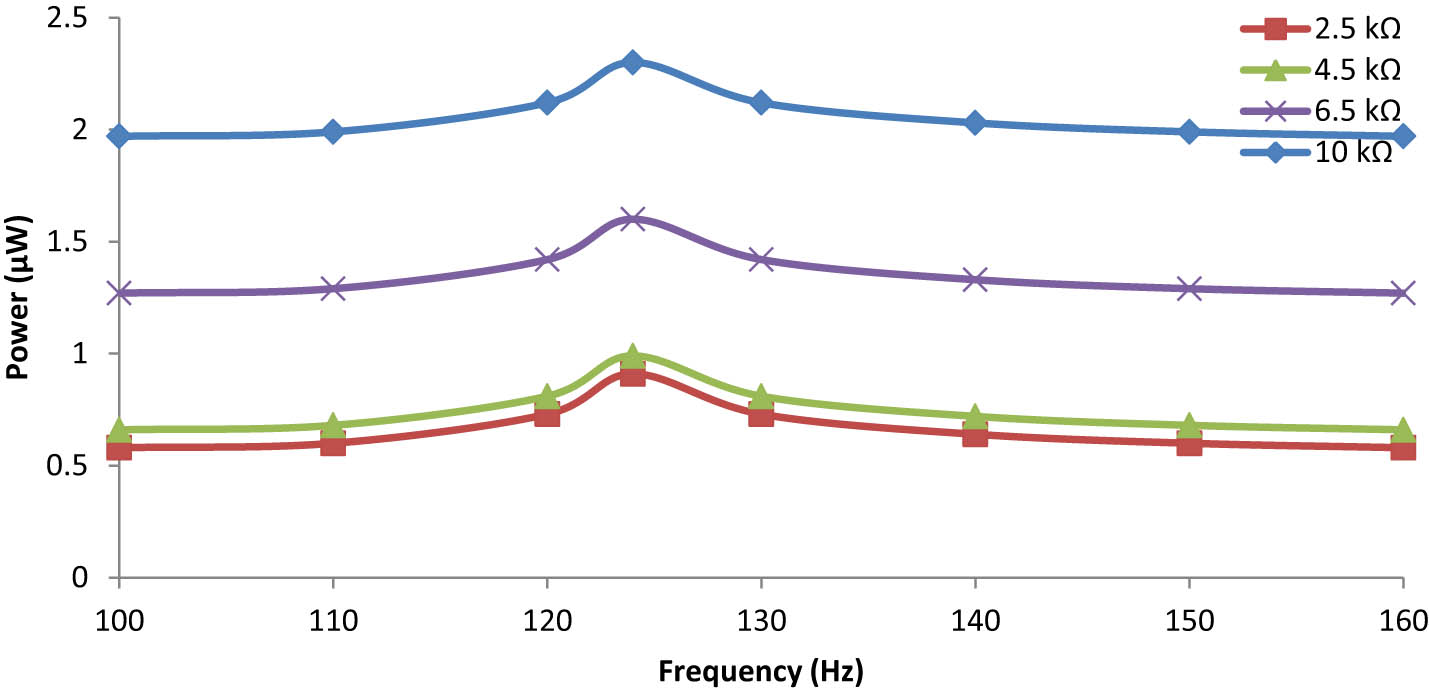
Frequency dependence output power of the embedded beam under 0.75 g.
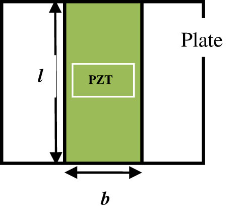
Plate with a line-type piezoelectric patch.
5.3.1 Line-type unimorph
In this case study, from Figure 20, it is observed that the maximum output power obtained is 1.39 μW under a gravitational acceleration of 0.75g at 117 Hz with a load resistance of 10 kΩ. Now, the remaining mass constant for another case, i.e. the cross-type unimorph plate is examined for its output performance. It is noticed that as the load resistance increases, the maximum power increases first, but after that, attenuation takes place when further load resistance is increased.
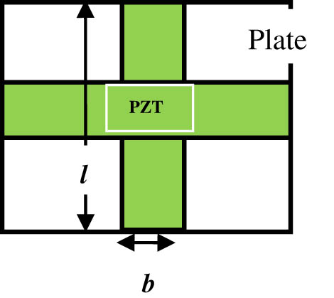
Plate with a cross-type piezoelectric patch.
5.3.2 Cross-type unimorph
In this case study, from Figure 21, it is observed that the maximum output power obtained is 1.44 μW under a gravitational acceleration of 0.75 g at 113 Hz with a load resistance of 10 kΩ, keeping the remaining mass constant. It is noticed that the output power increases slightly as compared to that of the line-type unimorph plate, and the frequency shifts to a lower side, which is remarkable.
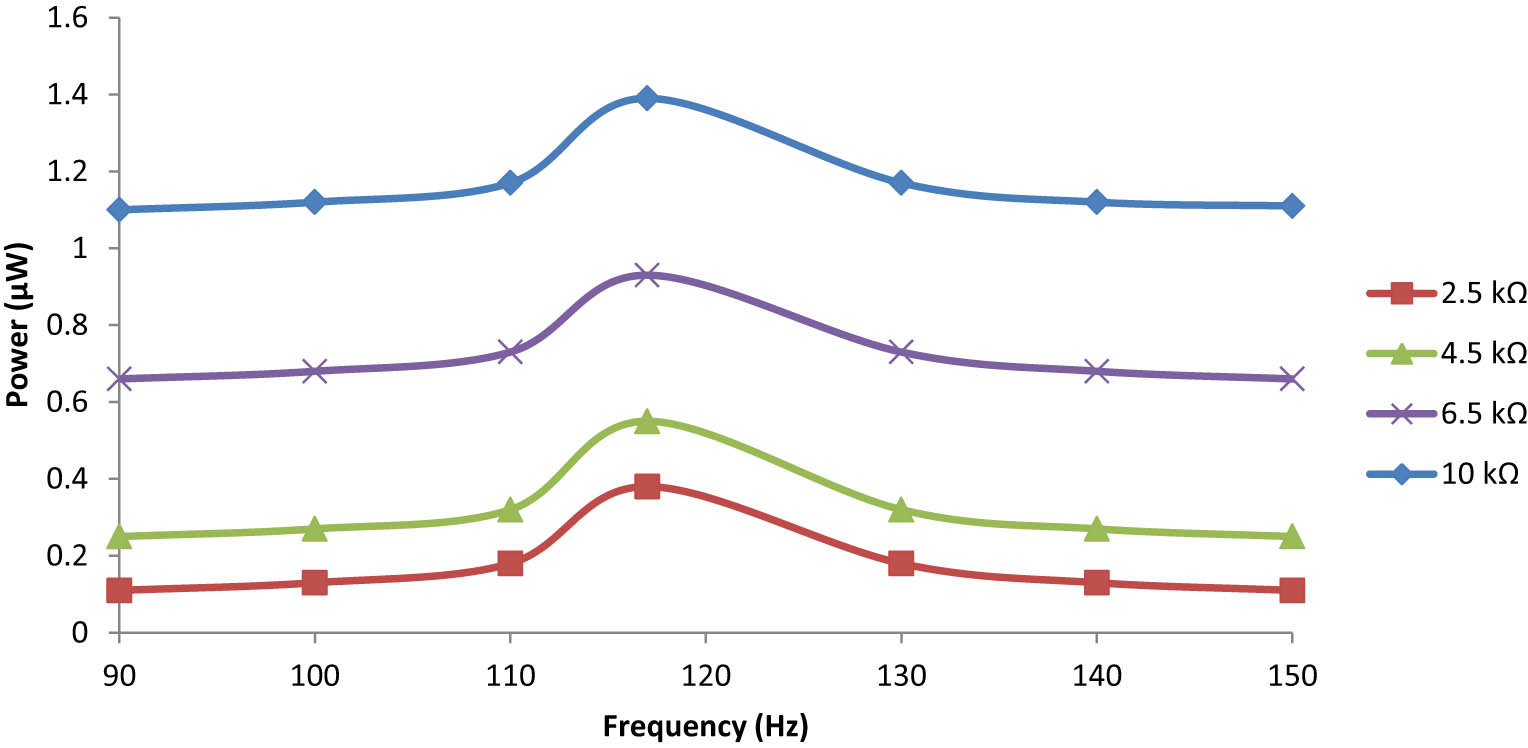
Frequency dependence output power for the line-type unimorph plate under 0.75 g.
5.3.3 Line-type bimorph
In this case study, from Figure 22, it is observed that the maximum output power obtained is 1.53 μW under a gravitational acceleration of 0.75 g at 124 Hz with a load resistance of 10 kΩ, keeping the remaining mass constant throughout all cases. Again, the maximum output power increases slightly, but in this case the frequency shifts to a higher side.
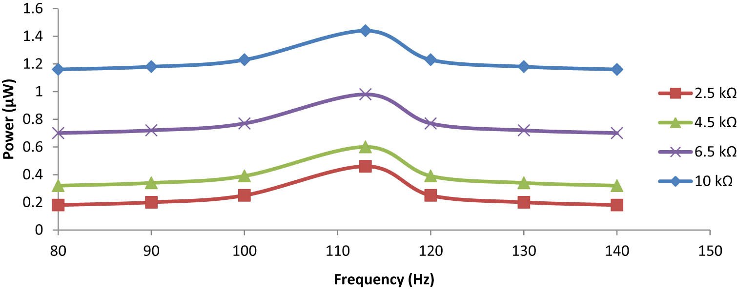
Frequency dependence output power for the cross-type unimorph plate under 0.75 g.
5.3.4 Cross-type bimorph
In this case study, from Figure 23, it is observed that the maximum power obtained is 1.66 μW under a gravitational acceleration of 0.75 g at 93 Hz with a load resistance of 10 kΩ. It is observed that wherever cross-type cases are considered, the frequency shifted to the lower side with an increase of the maximum output power.
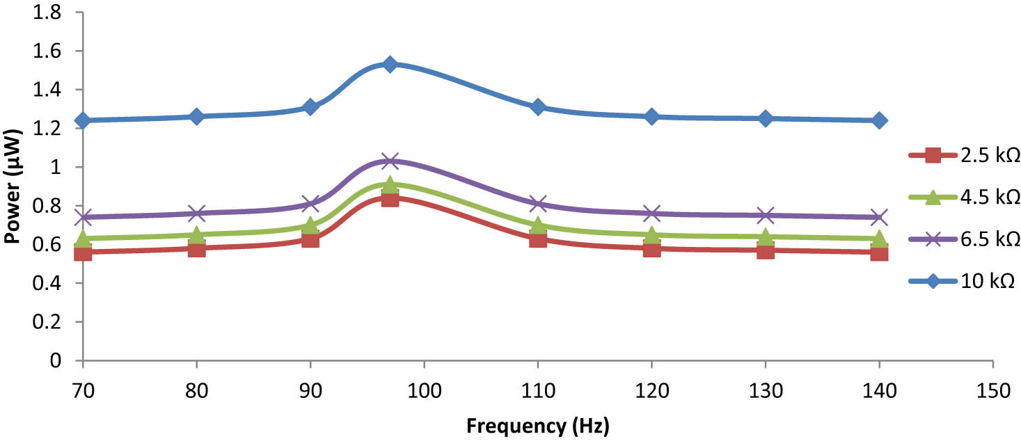
Frequency dependence output power for the line-type bimorph plate under 0.75 g.
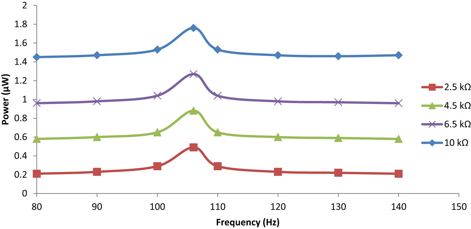
5.3.5 Line-type embedded
In this case study, from Figure 24, it is observed that the maximum output power obtained is 1.76 μW under a gravitational acceleration of 0.75 g at 106 Hz with a load resistance of 10 kΩ. Embedded plates are used to replace the existing materials, cut down on costs, and improve the output power performance. This type of plate is usually used to overcome the limited source of energy, limited size, and load capacity for any device where it is applicable. In this case study, again the proof mass is not added at the tip of the free end cantilever plate.
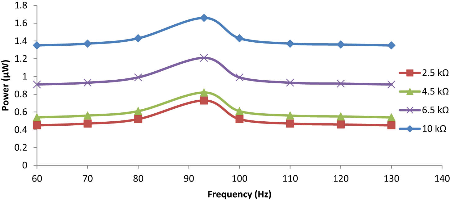
Frequency dependence on the output power for the cross-type bimorph plate under 0.75 g.
5.3.6 Cross-type embedded
In this case study, from Figure 25, it is observed that the maximum output power obtained is 2.03 μW under a gravitational acceleration of 0.75 g at 104 Hz with a load resistance of 10 kΩ (Figure 26).
Frequency dependence on the output power for the line-type embedded plate under 0.75 g.
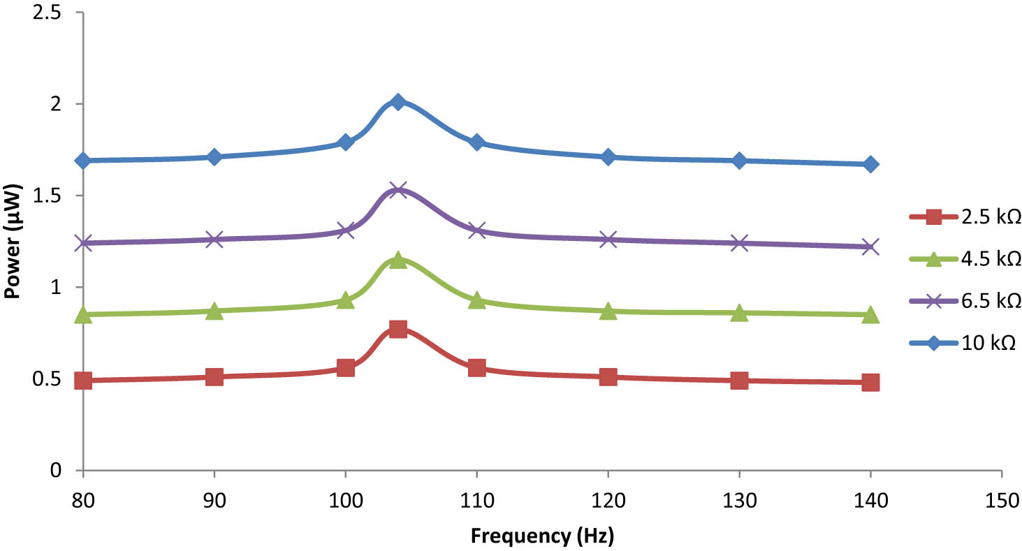
Frequency dependence on the output power for cross-type embedded plate under 0.75 g.
6 Conclusions
The following conclusions can be drawn from the results of the numerical simulation conducted for different cases:
The maximum value of the output power is about 2.8μW at a load resistance of 30 kΩ at 66 Hz for the piezoelectric cantilever beam without a host structure under external force applied.
For a piezoelectric unimorph cantilever beam, the maximum power is attained at 6.5 kΩ of the optimal resistance load, and the device had 147 mV of peak voltage and 0.42 μW under 0.75 g acceleration force at 162 Hz.
For a piezoelectric bimorph cantilever beam, the maximum power is attained at 10 kΩ of the optimal resistance load, and the device had 98 mV of peak voltage and 0.96 μW under 0.75 g acceleration force at 138 Hz.
For a piezoelectric embedded cantilever beam, the maximum output power obtained is 2.3 μW under the gravitational acceleration of 0.75 g at 124 Hz with a load resistance of 10 kΩ.
For a piezoelectric line-type unimorph cantilever plate, the maximum output power obtained is 1.39 μW under the gravitational acceleration of 0.75 g at 117 Hz with a load resistance of 10 kΩ.
For a piezoelectric cross-type unimorph cantilever plate, the maximum output power obtained is 1.44 μW under the gravitational acceleration of 0.75 g at 113 Hz with a load resistance of 10 kΩ, keeping the remaining mass constant.
For a piezoelectric line-type bimorph cantilever plate, the maximum output power obtained is 1.53 μW under the gravitational acceleration of 0.75 g at 124 Hz with a load resistance of 10 kΩ.
For a piezoelectric cross-type bimorph cantilever plate, the maximum output power obtained is 1.66 μW under the gravitational acceleration of 0.75 g at 93 Hz with a load resistance of 10 kΩ.
For a piezoelectric line-type embedded cantilever plate, the maximum output power obtained is 1.76 μW under the gravitational acceleration of 0.75 g at 106 Hz with a load resistance of 10 kΩ.
For a piezoelectric cross-type embedded cantilever plate, the maximum output power obtained is 2.03 μW under the gravitational acceleration of 0.75 g at 104 Hz with a load resistance of 10 kΩ.
7 Concluding remarks and future work
Numerical investigations on piezoelectric cantilever beams and plates with different cases reveal that the performance of output power is influenced by factors like load resistance, applications with and without host structures, and different design parameters like unimorph, bimorph, embedded, line-type, and cross-type piezoelectric patch arrangements, which are discussed in this article. The observations and data generated in the numerical work can be used to predict the estimation of the sound pressure level or sound power level at a given distance when the beam or plate vibrates under the influence of load resistance, applications of with and without host structures, and different design parameters with unimorph, bimorph, embedded, line- and cross-type piezoelectric patch arrangements.
-
Funding information: The authors are thankful to Manipal Institute of Technology, Manipal Academy of Higher Education & Alliance University, India for their support and required facility for the study.
-
Author contributions: The authors have contributed to the entire technical content of this manuscript and approved its submission.
-
Conflict of interest: Author states no conflict of interest.
-
Data availability statement: The raw data can be obtained on request from the corresponding author.
References
Anderson T. A. and Sexton D. W. (2006). “A vibration energy harvesting sensor platform for increased industrial efficiency,” Proceedings of SPIE – The International Society for Optical, p. 6174.10.1117/12.659586Search in Google Scholar
Atul and Deepak G. D. (2022). “Effectiveness of line type and cross type piezoelectric patches on active vibration control of a flexible rectangular plate,” Energy Harvesting Syst., vol. 9, no. 1, pp. 19–26.10.1515/ehs-2021-0048Search in Google Scholar
Atul, Ranjan V., and Pandey A. L. (2014). “Finite element modelling of piezoelectric cantilever with 31 effects for sensor application,” Sensors & Transducers, vol. 182, no. 11, pp. 281–287.Search in Google Scholar
Baker J., Roundy S., and Wright P. (2005). “Alternative geometries for increasing power density in vibration energy scavenging for wireless sensor networks,” 3rd International Energy Conversion Engineering Conference, San Francisco, California.10.2514/6.2005-5617Search in Google Scholar
Jiang S. N., Li X. F., Guo S. H., Hu Y. T., Yang J. S., and Jiang Q. (2005). “Performance of a piezoelectric bimorph for scavenging vibration energy,” Smart Materials and Structures, vol. 14, no. 4, pp. 769–774.10.1088/0964-1726/14/4/036Search in Google Scholar
Johnson T. J., Charnegie D., Clark W. W., Buric M., and Kusic G. (2006). “Energy harvesting from mechanical vibrations using piezoelectric cantilever beams,” Smart structures and materials 2006: Damping and Isolation, p. 6169.10.1117/12.659466Search in Google Scholar
Kim H. W., Batra A., Priya S., Uchino K., Markley D., Newnham R. E., et al. (2004). “Energy harvesting using a piezoelectric “cymbal” transducer in dynamic environment,” Japanese J. Appl. Phys., Part 1: Regular Papers and Short Notes and Review Papers, vol. 43, no. 9A, pp. 6178–6183.10.1143/JJAP.43.6178Search in Google Scholar
Ly R., Rguiti M., D’Astorg S., Hajjaji A., Courtois C., and Leriche A. (2011). “Modelling and characterization of piezoelectric cantilever bending sensor for energy harvesting,” Sensors and Actuators A: Physical, vol. 168, no. 1, pp. 95–100.10.1016/j.sna.2011.04.020Search in Google Scholar
Mateu L. and Moll F. (2005). “Optimum piezoelectric bending beam structures for energy harvesting using shoe inserts,” J. Intell. Mater. Syst. Struct., vol. 16, no. 10, pp. 835–845.10.1177/1045389X05055280Search in Google Scholar
Ng T. H. and Liao W. H. (2004). “Feasibility study of a self-powered piezoelectric sensor,” Smart Struct. Mater.: Smart Electron. MEMS Bio Mems Nanotechnol., vol. 5389, pp. 377–388.10.1117/12.539706Search in Google Scholar
Ng T. H. and Liao W. H. (2005). “Sensitivity analysis and energy harvesting for a self-powered piezoelectric sensor,” J. Intell. Mater. Syst. Struct., vol. 16, no. 10, pp. 785–797.10.1177/1045389X05053151Search in Google Scholar
Roundy S., Leland E. S., Baker J., Carleton E., Reilly E., Lai E., et al. (2005). “Improving power output for vibration-based energy scavengers,” IEEE Pervasive Computing, vol. 4, no. 1, pp. 28–36.10.1109/MPRV.2005.14Search in Google Scholar
Shahruz S. M. (2006). “Design of mechanical band-pass filters for energy scavenging,” J. Sound and Vib., vol. 292, no. 3–5, pp. 987–998.10.1016/j.jsv.2005.08.018Search in Google Scholar
© 2024 the author(s), published by De Gruyter
This work is licensed under the Creative Commons Attribution 4.0 International License.
Articles in the same Issue
- Solar photovoltaic-integrated energy storage system with a power electronic interface for operating a brushless DC drive-coupled agricultural load
- Analysis of 1-year energy data of a 5 kW and a 122 kW rooftop photovoltaic installation in Dhaka
- Reviews
- Real yields and PVSYST simulations: comparative analysis based on four photovoltaic installations at Ibn Tofail University
- A comprehensive approach of evolving electric vehicles (EVs) to attribute “green self-generation” – a review
- Exploring the piezoelectric porous polymers for energy harvesting: a review
- A strategic review: the role of commercially available tools for planning, modelling, optimization, and performance measurement of photovoltaic systems
- Comparative assessment of high gain boost converters for renewable energy sources and electrical vehicle applications
- A review of green hydrogen production based on solar energy; techniques and methods
- A review of green hydrogen production by renewable resources
- A review of hydrogen production from bio-energy, technologies and assessments
- A systematic review of recent developments in IoT-based demand side management for PV power generation
- Research Articles
- Hybrid optimization strategy for water cooling system: enhancement of photovoltaic panels performance
- Solar energy harvesting-based built-in backpack charger
- A power source for E-devices based on green energy
- Theoretical and experimental investigation of electricity generation through footstep tiles
- Experimental investigations on heat transfer enhancement in a double pipe heat exchanger using hybrid nanofluids
- Comparative energy and exergy analysis of a CPV/T system based on linear Fresnel reflectors
- Investigating the effect of green composite back sheet materials on solar panel output voltage harvesting for better sustainable energy performance
- Electrical and thermal modeling of battery cell grouping for analyzing battery pack efficiency and temperature
- Intelligent techno-economical optimization with demand side management in microgrid using improved sandpiper optimization algorithm
- Investigation of KAPTON–PDMS triboelectric nanogenerator considering the edge-effect capacitor
- Design of a novel hybrid soft computing model for passive components selection in multiple load Zeta converter topologies of solar PV energy system
- A novel mechatronic absorber of vibration energy in the chimney
- An IoT-based intelligent smart energy monitoring system for solar PV power generation
- Large-scale green hydrogen production using alkaline water electrolysis based on seasonal solar radiation
- Evaluation of performances in DI Diesel engine with different split injection timings
- Optimized power flow management based on Harris Hawks optimization for an islanded DC microgrid
- Experimental investigation of heat transfer characteristics for a shell and tube heat exchanger
- Fuzzy induced controller for optimal power quality improvement with PVA connected UPQC
- Impact of using a predictive neural network of multi-term zenith angle function on energy management of solar-harvesting sensor nodes
- An analytical study of wireless power transmission system with metamaterials
- Hydrogen energy horizon: balancing opportunities and challenges
- Development of renewable energy-based power system for the irrigation support: case studies
- Maximum power point tracking techniques using improved incremental conductance and particle swarm optimizer for solar power generation systems
- Experimental and numerical study on energy harvesting performance thermoelectric generator applied to a screw compressor
- Study on the effectiveness of a solar cell with a holographic concentrator
- Non-transient optimum design of nonlinear electromagnetic vibration-based energy harvester using homotopy perturbation method
- Industrial gas turbine performance prediction and improvement – a case study
- An electric-field high energy harvester from medium or high voltage power line with parallel line
- FPGA based telecommand system for balloon-borne scientific payloads
- Improved design of advanced controller for a step up converter used in photovoltaic system
- Techno-economic assessment of battery storage with photovoltaics for maximum self-consumption
- Analysis of 1-year energy data of a 5 kW and a 122 kW rooftop photovoltaic installation in Dhaka
- Shading impact on the electricity generated by a photovoltaic installation using “Solar Shadow-Mask”
- Investigations on the performance of bottle blade overshot water wheel in very low head resources for pico hydropower
- Solar photovoltaic-integrated energy storage system with a power electronic interface for operating a brushless DC drive-coupled agricultural load
- Numerical investigation of smart material-based structures for vibration energy-harvesting applications
- A system-level study of indoor light energy harvesting integrating commercially available power management circuitry
- Enhancing the wireless power transfer system performance and output voltage of electric scooters
- Harvesting energy from a soldier's gait using the piezoelectric effect
- Study of technical means for heat generation, its application, flow control, and conversion of other types of energy into thermal energy
- Theoretical analysis of piezoceramic ultrasonic energy harvester applicable in biomedical implanted devices
- Corrigendum
- Corrigendum to: A numerical investigation of optimum angles for solar energy receivers in the eastern part of Algeria
- Special Issue: Recent Trends in Renewable Energy Conversion and Storage Materials for Hybrid Transportation Systems
- Typical fault prediction method for wind turbines based on an improved stacked autoencoder network
- Power data integrity verification method based on chameleon authentication tree algorithm and missing tendency value
- Fault diagnosis of automobile drive based on a novel deep neural network
- Research on the development and intelligent application of power environmental protection platform based on big data
- Diffusion induced thermal effect and stress in layered Li(Ni0.6Mn0.2Co0.2)O2 cathode materials for button lithium-ion battery electrode plates
- Improving power plant technology to increase energy efficiency of autonomous consumers using geothermal sources
- Energy-saving analysis of desalination equipment based on a machine-learning sequence modeling