Improved design of advanced controller for a step up converter used in photovoltaic system
-
Nadia Ben Si Ali
 ,
Nadia Benalia
,
Nadia Benalia

Abstract
The expanding need for electricity has stimulated research and development of novel supply sources for energy production, conversion, and storage. Many studies are being done to increase the effectiveness of conversion systems as renewable energy is integrated into power networks on a larger scale. The global challenge is to minimize manufacturing costs and increase the use of sustainable resources. In this sense, photovoltaics is viewed as a particularly promising source due to the low cost of implementation and the wide range of applications it could be used for. This research focuses on the analysis, modeling, and simulation of a smart controller for a step-up converter that uses an artificial neural network (ANN) as a maximum power point tracking (MPPT) technique to provide maximum power. The proposed ANN-based algorithm is performed in Matlab/Simulink software, and its effectiveness has been demonstrated under varying climatic conditions.
1 Introduction
Interest in renewable energy sources has risen as a result of depleting energy supplies, rising environmental degradation, and global warming. The sun is the renewable energy source that is used the most frequently.
The solution is to use renewable energies which offer the possibility of producing electricity that meets ecological requirements, such as photovoltaic energy, but unfortunately this issue encounters economic constraints, high cost and low yield. The maximum power pursuit problem is among the problems of photovoltaic systems. This observation is confirmed by the large number of works concerning this problem encountered in the literature. Different maximum power point tracking MPPT methods have been used in the literature in order to achieve optimal performance. The most popular algorithm is perturb and observe (P&O) (Ben Si Ali, Zerzouri, and Benalia 2019; Derdar et al. 2021). The incremental conductance (INC) (Gupta, Chauhan, and Pachauri 2016; Manisha and Kumar 2021). The open-circuit voltage (OCV) (Tey and Mekhilef 2014), fuzzy logic method (Tey and Mekhilef 2014), genetic algorithm (Putri, Wibowo, and Rifa’i 2015). and MPPT algorithms based on neural networks in (Abdulrazzaq and Ali 2018; Hadji, Gaubert, and Krim 2018). Intelligence techniques play an important role in performance analysis, prediction, and control of renewable energy systems.
The main objective of this work is to investigate the performance of a solar system that uses an ANN MPPT technique for power maximization. The behavior and performance of PV panels utilizing this algorithm are assessed for climatic condition variations. The article is structured as follows: Section 1 describes the proposed system; Sections 2 and 3 present modeling and simulation of the PV system and step up converter, respectively; and Section 4 presents the proposed ANN-Based MPPT Algorithm, as well as its MATLAB/Simulink Simulation results and discussion. Section 6 conclusion.
2 System description
The system consists of photovoltaic PV panel connected to a load through a step-up DC-DC converter that uses an artificial neural network (ANN) as a maximum power point tracking (MPPT) algorithm to generate maximum power. The structure of the overall conversion chain is presented in Figure 1.

Structure of the overall converting chain.
3 Electrical equivalent circuit model of PV panel
A single solar cell can be modeled by using a current source, a diode, and two resistors (Rai et al. 2011; Salmi et al. 2012). This model is known as a single diode model. A PV array is a group of several PV cells which are electrically connected in series and parallel circuits to generate the required current and voltage (Figure 2).

Photovoltaic system.
Light induced current basically depends on irradiance and temperature.
The short-circuit current I sc is defined by:
The module-reverse saturation current I rs and I 0 which varies with cell temperature are given by:
The current voltage characteristics will be:
Nomenclature
- G
-
solar irradiance
- T
-
cell p-n junction temperature
- R sh
-
equivalent shunt resistance
- R s
-
equivalent series resistance
- I
-
output current
- V
-
output voltage
- I ph
-
photo generated electric current
- I sc
-
short circuit current
- I d
-
current at diode D
- K
-
Boltzman’s constant
- q
-
electron charge
- I s
-
diode reverse bias saturation current
- n
-
diode ideality factor
- N s
-
number of series cells
- E g
-
band gap energy of the semi-conductor.
Table 1 includes a datasheet and a list of the parameters for the PV panel Soltech 1STH-215-P used in Matlab Simulink. The first simulation is done for environmental condition variation for PV panels with two series modules and two parallel strings. The effect of application of different levels of irradiance as well as temperature on voltage-current (V–I) and voltage-power (V–P) is shown in Figure 3. The irradiance level and photo-generated current are directly related, therefore an increase in irradiation results in a larger photo-generated current. Additionally, because the photo generated current and short circuit current are particularly related, irradiance is directly proportional to both of them. It is clear that the variation in temperature mainly affects the open circuit voltage V oc. It decreases with temperature rise.
Electrical characteristics of 1Soltech 1STH-215-P module.
| Open circuit voltage (V oc) | 36.3 V |
| Short-circuit current (I sc) | 7.84 A |
| Voltage at MPP (V mp) | 29 V |
| Current at MPP (I mp) | 7.35 |
| Maximum power (P m ) | 213.15 w |
| N s | 96 |
| Voltage/temp. Coefficient VK | −0.38 %/°C |
| Current/temp. Coefficient I K | 0.065 %/°C |

PV characteristics for climatic condition variation. (a) I–V curves, (b) P–V curves.
In standard test condition STC conditions (G = 1000 w/m2, T = 25 °C) this panel generates a maximum power of 852.6 w corresponding to PV voltage of 58 V and a current of 15.68 A.
3.1 Step up converter design and control
Maximum Power Point Tracking (MPPT) is a technique used in photovoltaic (PV) systems to optimize the energy output of solar panels. PV systems rely on converting sunlight into electrical energy, and the amount of energy produced depends on various factors such as the angle of incidence of the sunlight, irradiation and temperature. The MPPT technology maximizes the power output of solar panels by continuously tracking and adjusting the operating point of the PV system to extract the maximum power available from the panels at any given time. Usually, in order to extract at all times, the maximum power available at the terminals of the photovoltaic module and transfer it to the load, an adaptation stage DC-DC converter is used. The proposed model incorporates a PV array and a step-up converter, which is used as an interface device connecting the PV panel to the load (Nema et al. 2010; Ram, Babu, and Rajasekar 2017).
The Step up DC-DC chopper is a power converter with a dc output voltage higher than its dc input voltage. It contains two semiconductors (diode, switch) and at least one energy storage element. The output capacity is added to reduce output voltage ripple (Figure 4). Relationship between input and output voltage and current are given by equation (5).

Step up converter.
The operation of the step-up boost converter can be divided into two modes, Mode 1 and Mode 2. Mode 1 begins when the transistor IGBT is switched on at time t = 0. The input current rises and flows through the inductor L and the transistor IGBT. Mode 2 begins when the transistor IGBT is switched off. The input current, in this case, flows through L, C, load, and diode D. The inductor current falls until the next cycle. The energy stored in inductor L flows through the load.
3.2 Component calculations
The design of the step up converter parameters is done according to equations in Table 2.
Design of the step up converter.
| Duty cycle | Load resistance | Inductor | Capacitor | Output current |
|---|---|---|---|---|
|
|
|
|
|
|
4 Conventional methods used for MPP tracking
4.1 Perturb and observe P&O technique
The Perturb and Observe (P&O) algorithm is regarded as the most popular because of its ease of use and effectiveness. The basic idea behind this technique is illustrated in Figure 5, where each iteration involves perturbing (increasing or decreasing) the array terminal voltage and observing the impact on the PV output power, then comparing it with the previous iteration’s value. If the power is increased, the perturbation will continue in its current direction; otherwise, it will reverse. The operating point begins to oscillate around the maximum power point (MPP) after it is achieved. This technique presents some limitations, such as an increase in power losses as a result of the steady state condition oscillation around the MPP, particularly in the case of big steps (Ram, Babu, and Rajasekar 2017). The (P&O) algorithm is sluggish during a quick change of atmospheric conditions. The flow chart in Figure 5 recapitulates the P&O algorithm.
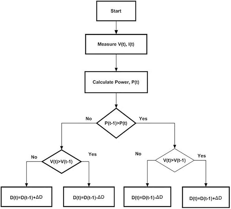
Flowchart of P&O algorithm.
4.2 Incremental conductance (INC) technique
As shown in Figure 6, the incremental conductance approach INC is based on tracking the MPP based on the slope of the solar panel’s output power. In this technique, the incremental conductance (ΔI/ΔV) and the instantaneous conductance (I/V) are compared. The terminal voltage of the PV array decreases if the slope of the P–V curve (ΔP/ΔV) is negative, indicating that the operating point is to the right of the MPP. If the slope is positive, the operating point is to the left of the MPP and the terminal voltage of the PV array is raised; if the slope is zero, the MPP is attained and the instantaneous and incremental conductances are equal (Chellal, Guimaraes, and Leite 2021).

Incremental conductance algorithm flowchart.
The first simulations were done for the perturb and observe P&O and incremental INC algorithms. Results have been established for T = 25 °C and variable irradiations to analyze the behavior of each technique (Figure 7). Figures 8 –13 show voltage and current of the PV panel and the load, PV power, and the duty cycle.

Radiation pattern.

Load and PV voltages and currents for the P&O algorithm.

PV power for the P&O algorithm.

Duty cycle for the P&O technique.

Load and PV voltages and currents for the for the INC technique.

PV power for the INC technique.

Duty cycle for INC technique.
At standard test conditions, STC The PV system performances using P&O and INC MPPT algorithms are shown. It is clear that for constant irradiation G = 1000 w/m2, P&O finds MPP quickly but oscillates at MPP. As shown in Figure 12, INC finds MPP after a time delay. But the oscillations at constant irradiation are less as compared to P&O. Duty cycle dynamics of both algorithms for variable climatic conditions show that for P&O, D is perturbed continuously and results in greater oscillation at MPP with better tracking performances for instantaneous variation or quick slope of irradiance. While for INC, D presents less oscillation at MPP and more time to reach steady state. Thus, in order to overcome these limitations of conventional MPPT techniques, an efficient MPPT algorithm is needed. For this reason, a neural network MPPT algorithm is proposed.
5 Basic structure of neural network
The neural network technology is composed of a huge number of interconnected processors known as neurons. Each neuron has an important number of weighted connections for signal processing. As a result, it may be able to handle the challenging task of data processing and interpretation. Basically, the architecture consists of three types of neuron layers: the input layer, the hidden layer, and the output layer. A simple neuron model is shown in Figure 14. There are different activation functions that can be used (Khanam and Foo 2018). A mathematical model of the output of a neuron k can be written as:

Basic structure of neuron.
The output neuron is obtained by summing each of the input signals after they have been multiplied by the connection weights. The proposed ANN in this study is a feed-forward neural network. The input layers represent the irradiance and temperature. The output layer is the voltage Vmpp corresponding to the maximum power generated by the panel. A duty cycle signal is then applied for adjusting PV voltage through the boost converter. The ANN Adaptive Neural Network for MPPT is shown in Figure 15.

ANN adaptive neural network for MPPT.
Figure 16 shows the topology that has been suggested and simulated in Matlab/Simulink. The NN algorithm provides the gate signal for the DC-DC converter. The algorithm uses the solar PV module’s temperature and irradiance to calculate the appropriate voltage to optimize for generating a referenced duty cycle for the dc-dc step up converter.

ANN MPPT based structure.
6 Training data for learning (inputs and targets)
The ANN of MPPT is obtained from the PV model parameters presented in Section 2. The tansig is an activation function for the input layer. The purelin is the activation function for the output layer. A Mean Square Error criterion is used in training the network for determination of error. The Levenberg-Marquardt (LM)optimization technique is a network learning function (Trainlm) that amends weight and bias values (Khabou, Souissi, and Aitouche 2020; Motahhir, El Hammoumi, and El Ghzizal 2020). When required performances are achieved, the trained ANN becomes ready to track the MPP. The difference in voltage generated by the PV panel and the voltage generated by a trained artificial neural network is fed into the PI controller, whose output is compared to a high frequency signal to generate duty cycle. The flowchart, showing the training process is presented in Figure 17. Inputs and target variables obtained by the training process are presented in Figure 18. Some of the data are presented in Table 3. Neural network training is done using nntraintool (Figure 19).

Training process flowchart.

Data of the training process: Inputs (a) temperature T, (b) radiation G, (c) target Vmpp.
A sample of some ANN training data.

Feed-forward neural network.
The command gensim (net) is used to develop a SIMULINK block for neural networks. The global Simulink model consists of two layers, as shown in Figure 20. The structures of layer 1 and layer 2 are shown in Figure 21.

Simulink model of neural network input layers.

Structure of layer.
The success of the ANN was measured using mean square error (MSE) and regression coefficient (Bataineh 2018; Khanaki, Radzi, and Marhaban 2013). Figure 22 shows validation performance graph obtained for the optimal value of the objective function of the network where training data, testing data and validation data are very close to each other. Best validation value is MSE = 1.802e−10 obtained at epoch 1000.

Validation performance graph.
Regression plot a graph for each of training, validation and test cases and average of the three make a plot graph mention as all. It is observed from Figure 23 that all the samples are aligned on the same line which represent a high accuracy of the acquisition of data and the validity of them.

Regression graph of the network.
The Simulink model shown in Figure 24 is the block diagram of the PV array connected to a resistive load through a dc/dc step up converter with artificial neuron network MPPT controller. It is used to simulate dynamic behavior and power generated using this algorithm with irradiation and temperature variation patterns. The three methods were tested and compared under different scenarios. Figure 25 shows generated power and Figure 26 shows input and output voltages and currents. Variations in solar irradiance and temperature are applied to check and evaluate the robustness of the proposed controller.

Matlab/simulink model of pv panel with ANN Algorithm.

PV power with ANN algorithm.

Load and PV voltages and currents for the ANN algorithm.
Figures 27 –30 show simulation results of P&O, INC and ANN algorithm for maximum power point tracking for atmospheric condition variation. It is clear that all of NN, P&O, and INC track MPP with varying degrees of efficiency and accuracy. the NN algorithm has a fast response it takes less time to reach MPP, with high efficiency and less oscillation compared with traditional methods.

Irradiance variation.

PV power obtained applying P&O, INC and ANN algorithm for irradiation variation.

Temperature variation.

PV power obtained applying P&O, INC and ANN algorithm for temperature variation.
7 Conclusions
The present research investigates how artificial neural networks (ANN) may be used to improve MPPT accuracy and smoothness in solar power systems. The efficiency of solar manufacturing processes under fast and slow-changing atmospheric scenarios is proven through a comparison study of maximum power point tracking approaches. The behavior of a PV system is studied using conventional methods such as perturb and observe, incremental conductance, and the intelligently proposed ANN technique. Before using the ANN-suggested method, data collection must be done by selecting the network structure, then training it, and finally testing the network. Based on the simulation findings, it can be shown that all approaches are stable at MPP, although P&O and INC overshoot when the irradiance varies quickly. The findings show that applying the ANN algorithm allows tracking of the MPP faster and with reduced fluctuations, which enhances efficiency, improves robustness, and minimizes power losses.
-
Author contributions: All the authors have accepted responsibility for the entire content of this submitted manuscript and approved submission.
-
Research funding: No funding.
-
Conflict of interest statement: The authors declare no conflicts of interest regarding this article.
References
Abdulrazzaq, A. A., and A. H. Ali. 2018. “Efficiency Performances of Two MPPT Algorithms for PV System with Different Solar Panels Irradiances.” International Journal of Power Electronics and Drive Systems 9 (4): 1751–64.10.11591/ijpeds.v9.i4.pp1755-1764Search in Google Scholar
Bataineh, K. 2018. “Improved Hybrid Algorithms-Based MPPT Algorithm for PV System Operating under Severe Weather Conditions.” IET Power Electronics 12 (4): 703–11. https://doi.org/10.1049/iet-pel.2018.5651.Search in Google Scholar
Ben Si Ali, N., N. Zerzouri, and N. Benalia. 2019. “New Sudoku PV Array Configuration for Out Put Power Losses Minimization.” Internatıonal Journal of Natural and Engineering Sciences 13 (2): 59–62.Search in Google Scholar
Chellal, M., T. F. Guimaraes, and V. Leite. 2021. “Experimental Evaluation of Mppt Algorithms: A Comparative Study.” International Journal of Renewable Energy Resources 11 (1): 486–94.Search in Google Scholar
Derdar, A., N. Ben Si Ali, M. Adjabi, and N. Boutasseta. 2021. “Modeling of the ND 240QCJ SHARP Photovoltaic Solar Module and Study the Influence of the Variation of the Parameters.” Procedia Computer Science 194: 237–45, https://doi.org/10.1016/j.procs.2021.10.079.Search in Google Scholar
Gupta, A., Y. K. Chauhan, and K. Pachauri. 2016. “A Comparative Investigation of Maximum Power Point Tracking Methods for Solar PV Systems.” Solar Energy 136: 236–53. https://doi.org/10.1016/j.solener.2016.07.001.Search in Google Scholar
Hadji, S., J.-P. Gaubert, and F. Krim. 2018. “Real-Time Genetic Algorithms-Based MPPT: Study and Comparison (Theoretical an Experimental) with Conventional Methods.” Energies 11: 459. https://doi.org/10.3390/en11020459.Search in Google Scholar
Khabou, H., M. Souissi, and A. Aitouche. 2020. “MPPT Implementation on Boost Converter by Using T–S Fuzzy Method.” Mathematics and Computers in Simulation 167: 119–34. https://doi.org/10.1016/j.matcom.2018.05.010.Search in Google Scholar
Khanaki, R., M. A. M. Radzi, and M. H. Marhaban. 2013. “Comparison of ANN and P&O MPPT Methods for PV Applications under Changing Solar Irradiation.” In IEEE Conference on Clean Energy and Technology, Langkawi, Malaysia.10.1109/CEAT.2013.6775642Search in Google Scholar
Khanam, J., and S. Y. Foo. 2018. “Neural Networks Technique for Maximum Power Point Tracking of Photovoltaic Array.” In South East Con 2018. St. Petersburg, FL, USA: IEEE.10.1109/SECON.2018.8479054Search in Google Scholar
Manisha, K., and N. Kumar. 2021. “Comparative Study of Different MPPT Techniques for PV System.” In International Conference for Emerging Technology, Belgaum, India. May 21–23, 2021.10.1109/INCET51464.2021.9456271Search in Google Scholar
Motahhir, S., A. El Hammoumi, and A. El Ghzizal. 2020. “The Most Used MPPT Algorithms: Review and the Suitable Low-Cost Embedded Board for Each Algorithm.” Journal of Cleaner Production 246: 118983. https://doi.org/10.1016/j.jclepro.2019.118983.Search in Google Scholar
Nema, S., R. K. Nema, and G. Agnihotri. 2010. “Matlab/simulink Based Study of Photovoltaic Cells/modules/array and Their Experimental Verification.” International Journal of Energy and Environment 1 (3): 487–500.Search in Google Scholar
Putri, R. I., S. Wibowo, and M. Rifa’i. 2015. “Maximum Power Point Tracking for Photovoltaic Using Incremental Conductance Method.” Energy Procedia 68: 22–30. https://doi.org/10.1016/j.egypro.2015.03.228.Search in Google Scholar
Rai, A. K., N. D. Kaushika, B. Singh, and N. Agarwal. 2011. “Simulation Model of ANN Based Maximum Power Point Tracking Controller for Solar PV System.” Solar Energy Materials and Solar Cells 95 (2): 773–8. https://doi.org/10.1016/j.solmat.2010.10.022.Search in Google Scholar
Ram, J. P., T. S. Babu, and N. Rajasekar. 2017. “A Comprehensive Review on Solar PV Maximum Power Point Tracking Techniques.” Renewable and Sustainable Energy Reviews 67: 826–47. https://doi.org/10.1016/j.rser.2016.09.076.Search in Google Scholar
Salmi, T., M. Bouzguenda, A. Gastli, and A. Masmoudi. 2012. “Matlab/Simulink Based Modelling of Solar Photovoltaic Cell.” International Journal of Renewable Energy Research 2 (2): 213–8.Search in Google Scholar
Tey, K. S., and S. Mekhilef. 2014. “Modified Incremental Conductance MPPT Algorithm to Mitigateinaccurate Responses under Fast-Changing Solar Irradiation Level.” Solar Energy 101: 333–42.10.1016/j.solener.2014.01.003Search in Google Scholar
© 2024 the author(s), published by De Gruyter, Berlin/Boston
This work is licensed under the Creative Commons Attribution 4.0 International License.
Articles in the same Issue
- Solar photovoltaic-integrated energy storage system with a power electronic interface for operating a brushless DC drive-coupled agricultural load
- Analysis of 1-year energy data of a 5 kW and a 122 kW rooftop photovoltaic installation in Dhaka
- Reviews
- Real yields and PVSYST simulations: comparative analysis based on four photovoltaic installations at Ibn Tofail University
- A comprehensive approach of evolving electric vehicles (EVs) to attribute “green self-generation” – a review
- Exploring the piezoelectric porous polymers for energy harvesting: a review
- A strategic review: the role of commercially available tools for planning, modelling, optimization, and performance measurement of photovoltaic systems
- Comparative assessment of high gain boost converters for renewable energy sources and electrical vehicle applications
- A review of green hydrogen production based on solar energy; techniques and methods
- A review of green hydrogen production by renewable resources
- A review of hydrogen production from bio-energy, technologies and assessments
- A systematic review of recent developments in IoT-based demand side management for PV power generation
- Research Articles
- Hybrid optimization strategy for water cooling system: enhancement of photovoltaic panels performance
- Solar energy harvesting-based built-in backpack charger
- A power source for E-devices based on green energy
- Theoretical and experimental investigation of electricity generation through footstep tiles
- Experimental investigations on heat transfer enhancement in a double pipe heat exchanger using hybrid nanofluids
- Comparative energy and exergy analysis of a CPV/T system based on linear Fresnel reflectors
- Investigating the effect of green composite back sheet materials on solar panel output voltage harvesting for better sustainable energy performance
- Electrical and thermal modeling of battery cell grouping for analyzing battery pack efficiency and temperature
- Intelligent techno-economical optimization with demand side management in microgrid using improved sandpiper optimization algorithm
- Investigation of KAPTON–PDMS triboelectric nanogenerator considering the edge-effect capacitor
- Design of a novel hybrid soft computing model for passive components selection in multiple load Zeta converter topologies of solar PV energy system
- A novel mechatronic absorber of vibration energy in the chimney
- An IoT-based intelligent smart energy monitoring system for solar PV power generation
- Large-scale green hydrogen production using alkaline water electrolysis based on seasonal solar radiation
- Evaluation of performances in DI Diesel engine with different split injection timings
- Optimized power flow management based on Harris Hawks optimization for an islanded DC microgrid
- Experimental investigation of heat transfer characteristics for a shell and tube heat exchanger
- Fuzzy induced controller for optimal power quality improvement with PVA connected UPQC
- Impact of using a predictive neural network of multi-term zenith angle function on energy management of solar-harvesting sensor nodes
- An analytical study of wireless power transmission system with metamaterials
- Hydrogen energy horizon: balancing opportunities and challenges
- Development of renewable energy-based power system for the irrigation support: case studies
- Maximum power point tracking techniques using improved incremental conductance and particle swarm optimizer for solar power generation systems
- Experimental and numerical study on energy harvesting performance thermoelectric generator applied to a screw compressor
- Study on the effectiveness of a solar cell with a holographic concentrator
- Non-transient optimum design of nonlinear electromagnetic vibration-based energy harvester using homotopy perturbation method
- Industrial gas turbine performance prediction and improvement – a case study
- An electric-field high energy harvester from medium or high voltage power line with parallel line
- FPGA based telecommand system for balloon-borne scientific payloads
- Improved design of advanced controller for a step up converter used in photovoltaic system
- Techno-economic assessment of battery storage with photovoltaics for maximum self-consumption
- Analysis of 1-year energy data of a 5 kW and a 122 kW rooftop photovoltaic installation in Dhaka
- Shading impact on the electricity generated by a photovoltaic installation using “Solar Shadow-Mask”
- Investigations on the performance of bottle blade overshot water wheel in very low head resources for pico hydropower
- Solar photovoltaic-integrated energy storage system with a power electronic interface for operating a brushless DC drive-coupled agricultural load
- Numerical investigation of smart material-based structures for vibration energy-harvesting applications
- A system-level study of indoor light energy harvesting integrating commercially available power management circuitry
- Enhancing the wireless power transfer system performance and output voltage of electric scooters
- Harvesting energy from a soldier's gait using the piezoelectric effect
- Study of technical means for heat generation, its application, flow control, and conversion of other types of energy into thermal energy
- Theoretical analysis of piezoceramic ultrasonic energy harvester applicable in biomedical implanted devices
- Corrigendum
- Corrigendum to: A numerical investigation of optimum angles for solar energy receivers in the eastern part of Algeria
- Special Issue: Recent Trends in Renewable Energy Conversion and Storage Materials for Hybrid Transportation Systems
- Typical fault prediction method for wind turbines based on an improved stacked autoencoder network
- Power data integrity verification method based on chameleon authentication tree algorithm and missing tendency value
- Fault diagnosis of automobile drive based on a novel deep neural network
- Research on the development and intelligent application of power environmental protection platform based on big data
- Diffusion induced thermal effect and stress in layered Li(Ni0.6Mn0.2Co0.2)O2 cathode materials for button lithium-ion battery electrode plates
- Improving power plant technology to increase energy efficiency of autonomous consumers using geothermal sources
- Energy-saving analysis of desalination equipment based on a machine-learning sequence modeling