Experimental study on enhancement characteristics of steam/nitrogen condensation inside horizontal multi-start helical channels
-
Jianjun Wen
 und
Dan Zheng
und
Dan Zheng

Abstract
The aim of this study was to reveal the internal mechanism of enhanced condensation heat transfer, by experimentally performing steam condensation with higher inlet velocity in the horizontal multi-start helical channels (HMSHCs), and investigating the influences of pressure of steam, mass flowrate of cooling water, and mass fraction of noncondensable (NC) gas on steam condensation performance. Taking steam condensation in horizontal circular condensation channel (HCCC) as a reference, the condensation heat transfer coefficients (CHTCs), the outlet condensate mass flowrates (CMFRs), and the total steam condensation pressure drops (SCPDs) were compared and discussed, respectively. The results indicated that NC gas had a strong inhibitory effect on steam condensation, and average condensation characteristics decreased with the increase in NC gas fraction for lower Rem. But for higher Rem, the gas–liquid interfacial shearing stress can likely weaken the negative effect of NC gas. In addition, increasing the cooling water flowrate can entirety promote steam condensation. The comparison results indicated that steam condensation performance of HMSHC is better than that of HCCC under same experimental conditions. For the specific experimental scope, the average CHTCs and the outlet CMFRs in HMSHC are approximately 2.35 and 1.25 times of that inside HCCC, respectively, while the overall SCPDs in HMSHC are about 1.16 times of that inside HCCC. After introducing the performance evaluation factor, the calculation results revealed that the performance evaluation factor
Nomenclature
- c p
-
specific heat capacity at constant pressure, J kg−1 K−1
- d
-
tube diameter, m
- G
-
specific mass flux, kg m−2 s−1
- h
-
heat transfer coefficient, W m−2 K−1
- H
-
enthalpy, kJ kg−1
- J s
-
dimensionless steam velocity (Wallis parameter)
- m
-
mass flowrate, kg h−1
- Nu
-
Nusselt number
- Pr
-
Prandtl number
- Re
-
Reynolds number
- T
-
temperature, K
- x
-
steam quality
- X tt
-
Martinelli number
Greek symbols
- λ
-
thermal conductivity, W m−1 K−1
- μ
-
dynamic viscosity, Pa s
- ρ
-
density, kg m−3
- Φ
-
heat flowrate, W
- ω
-
mass fraction of NC gas
Subscripts
- c
-
condensate or condensation
- e
-
Enhancement
- i
-
inner, interface
- l
-
liquid
- m
-
mixture
- n
-
nitrogen
- o
-
outer
- r
-
reference
- s
-
steam
-
-
uncondensed steam
- w
-
wall
Superscripts
- ′
-
entrance
- ″
-
exit
- +
-
absorption
- −
-
release
Abbreviations
- CHTC
-
condensation heat transfer coefficient
- CMFR
-
condensate mass flowrate
- ETS
-
experimental test section
- HCCC
-
horizontal circular condensation channel
- HMSHC
-
horizontal multi-start helical channel
- NC
-
noncondensable
- NCGMF
-
noncondensable gas mass fraction
- SCPDs
-
steam condensation pressure drops
1 Introduction
Due to the strong heat transfer ability, constant temperature control, compact structure, and other advantages, steam condenser of the horizontal in-tube condensation type are widely used in many industrial fields. However, in the horizontal restricted channels, there are numerous factors restraining steam condensation, making the condensation process extremely complicated due to the symmetrical and nonuniform distribution characteristics of the liquid film in the axial and circumferential directions. Especially when there is a small amount of noncondensable (NC) gas, the existence of NC gas will deteriorate seriously the heat transfer performance because of the NC gas diffusion layer [1,2]. Therefore, exploring the horizontal enhanced condensation channels to improve the steam condensation characteristics is of great significance for the optimal design of condensers.
The effect of the NC gas mass fractions (NCGMFs) on the steam condensation characteristics has been extensively studied both experimentally [3,4,5,6,7,8,9,10,11,12,13,14,15] and theoretically [16,17,18,19,20,21] in the horizontal restricted channels. In this respect, Othmer [5] was the first to carry out experimental research on the condensation of steam-air mixture on an isothermal condensing surface. It was surprisingly found that, when the air concentration is 0.5%, the average condensation heat transfer coefficient (CHTC) is 50% lower than that of pure steam, which arouse many scholars’ interest in the research of steam condensation in the presence of NC gas. Sideman et al. [6] conducted an experimental investigation on the effects of tube cross-section shape and air mass fraction on steam condensation characteristics under different conditions. He found that the average CHTC of steam with 3% air is 65% lower than that of pure steam in the horizontal condenser tube, and the average CHTC in the horizontal elliptical tube is 20% higher than that in the horizontal circular tube, under the same conditions. Nakamura et al. [7] experimentally assessed the impact of NCGMFs on the average value of steam CHTCs in the horizontal single U-tube under the postulated severe accident conditions. They found that NCGMFs had an insignificant impact on the average CHTCs in the horizontal single U-tube even at high NCGMFs. Wu and Vierow [8] experimentally studied the effect of NCGMFs on the average CHTC of vapor condensation in the horizontal condenser tube, and investigated the asymmetrical heat transfer characteristics around the condenser tube periphery. They found that the CHTCs of the tube top and tube bottom surface near the entrance and near the outlet of the condenser tube were significantly different for lower mixture inlet Reynolds number.
Caruso et al. [9,10,11] experimentally investigated the steam condensation characteristics inside the condenser tubes with different inclination angles in a wide range of NCGMF. The effect of tube diameter (12.6, 20, and 26.8 mm), air mass fraction (2–42%), and tube inclination (0, 7, 15, 30, and 45°) on the average CHTCs of steam condensation were analyzed. The criterion correlations to evaluate the local CHTCs of the steam/air mixtures condensation were proposed. They found that NC gas did reduce the steam condensation characteristics inside the condenser tubes with different inclination angles, and that the predicted Nucal was in good agreement with the experimental Nuexp for gravity-controlled stratified flow. Ren et al. [12] experimentally investigated the steam condensation characteristics in the horizontal circular condensation channel (HCCC) in the presence of NC gas, and analyzed the effect of NCGMFs on the local CHTCs near the entrance and the outlet of the condensing tube. The correlations of the local CHTCs, respectively, for the stratified or annular flow regimes were developed, and the error was within ±20%. They found that, near the entrance of the condenser tube, the local CHTCs at the bottom of the condenser tubes were smaller than that at the top of the tubes due to the asymmetrical liquid film thickness profile. While near the outlet of the condensing tube, the relative deviation gradually decreased along the axis direction of the condenser tube, especially at higher NCGMFs.
Cheng et al. [13] experimentally studied the steam condensation characteristics with higher inlet velocity in a small horizontal rectangular channel. It was found that the overall CHTCs could go down by 26.4% with an 8% inlet NCGMF, while NCGMF had no evident influence on steam condensation performance when inlet mixture mass flux was large. Xu et al. [14] experimentally investigated the steam condensation performances for annular, wavy, and stratified flow inside a horizontal tube containing multicomponent NC gases. They found that the local CHTCs increased with the increase in the condensation temperature difference for annular and wavy flow but decreased for stratified flow. Moreover, they also displayed that the calculated Nucal from the proposed correlation were in good agreement with the experimental Nuexp with satisfactory engineering accuracy.
Shen et al. [15] performed an experimental investigation on steam condensation characteristics for the stratified flow regime in a horizontal vacuum tube. They found that the local CHTCs in film condensation section were evidently higher than that in the condensate gathering section, and the former decreased with the increase in the condensation temperature difference, while the latter had less effect on that. Furthermore, new correlations for predicting the local CHTCs of steam condensation in the horizontal vacuum tube under stratified flow pattern were proposed.
Due to the uneven circumferential distribution structure of liquid film inside the horizontal tube, most studies on the heat transfer characteristics of steam condensation in horizontal tube used experimental methods. However, some scholars have simplified the flow and heat transfer process in the horizontal tube and obtained a series of simple models for calculating the CHTCs. Lee and Kim [19] developed a theoretical model to investigate steam condensation performances with NC gas inside a horizontal condenser tube. The method of heat and mass analogy was applied to analyze the steam/NC gas mixture boundary layer. It was found that, for stratified flow with higher mixture velocity, based on the measured data at the bottom of the horizontal condenser tube, the local CHTCs obtained from the theoretical model slightly overestimated those calculated by theoretical formula. While based on the experimental data at the top of the horizontal condenser tube, the local CHTCs obtained from the theoretical model slightly underestimated those calculated by theoretical formula. In addition, the predicted CHTCs of the empirical correlation proposed by Lee and Kim [20] were in good agreement with those of the theoretical model. Ahn et al. [21] proposed a steam condensation heat transfer model package to improve the prediction capability of the upper and lower parts of the nearly-horizontal tube under the air-water and steam-water separated flow conditions, when considering the effects of interfacial shear stress resulting from a high convective steam flow. The experimental results showed that the calculative h cal of the model was in good agreement with the experimental h exp with only an average deviation of 6.2%, which indicated that the prediction performance of the condensation model was significantly improved.
About strengthening the condensation heat transfer, other scholars have also proposed many technologies of enhanced condensation heat transfer in the horizontal channel. For example, some horizontal microfin tubes with external extended surface (such as 3-D finned tubes, spiral finned tubes, serrated finned tubes, slotted finned tubes, etc.) [22,23], some horizontal non-circular channels (such as triangular channels, elliptical channels, rectangular channels, etc.), microchannel, and enhanced heat exchanger with nanoparticles are used for heat transfer enhancement [24,25,26,27,28,29]. However, most of the working fluids in the literature are concentrated on water, refrigerants, nanofluids, and so on, and less on steam enhancement condensation in the horizontal channels.
Although many researchers have studied steam condensation characteristics in the horizontal confined channel through experiments, theories, and even simulations, most of them are low steam flow velocity or are mostly in horizontal smooth tubes, and very few works were performed to study steam condensation characteristics inside the horizontal enhanced condensation channels with NC gas. Therefore, in this study, nitrogen was used as NC gas (ω i,n = 0–10%), steam/nitrogen condensation experiments inside horizontal multi-start helical channel (HMSHC) would be performed and compared with that inside HCCC under same conditions.
2 Experimental system and procedure
The schematic diagram of steam condensation experiment is shown in Figure 1, which were composed of steam pipeline system, NC gas pipeline system, cooling water pipeline system, experimental test section (ETS), data acquisition system, and so on. Forty-five T-type thermocouples with the precision less than ±0.1°C, seven Rosemount pressure transducers with the precision less than ±0.065%, and six Coriolis mass flowmeter with the precision less than ±0.02% were installed on the pipeline to measure the temperature, pressure, and mass flowrate, respectively.

Schematic diagram of steam condensation experiment.
The cooling water softened by FLECK water softener was used as coolant, and stored separately in the cooling water tank and in the condensate tank to be used. The steam required for the experiment was supplied by a steam generator, under the rated conditions, with corresponding pressure of 0.7 MPa, temperature of 170℃, and mass flowrate of 65 kg h−1. Nitrogen was used as NC gas in the study, which was provided by high pressure gas cylinders, its pressure and mass flowrate were controlled by decompression valve, and its temperature was controlled by the preheater. Then, the steam (saturated pure steam) and the nitrogen (meeting the required state, with inlet NCGMF of 0–10%) were thoroughly mixed in the mixer. Here gas–liquid mixture (steam + nitrogen + condensate) in the condensing tube was used as thermal fluid.
The ETS of HCCC was a concentric-tube heat exchange consisting of two stainless steel tubes, and an annular interlayer was formed between the inner and outer tubes. The thermal fluid flowed inside the inner tube (the condenser tube), while the coolant flowed reversely in the annular interlayer. The ETS was well insulated, and the heat transfer between steam/nitrogen mixture and cooling water was mainly carried out through the condenser tube. In the ETS, due to condensation, the steam ceaselessly turned into the condensate to release heat, and NC gas (nitrogen) moved toward steam-condensate interface where they accumulate, and the temperature of the cooling water after absorbing heat raised correspondingly. The gas–liquid mixture in the condenser tube flowed out of the ETS into the 1# gas–liquid separator. The condensate separated from the gas–liquid mixture flowed through ball float drain valve and flowed into the condensate tank. Then, the uncondensed steam and NC gas nitrogen mixture flowed into a water-gas cooler to make the uncondensed steam condense thoroughly. Finally, another condensate separated again by 2# gas–liquid separator flows through ball float drain valve and also into the condensate tank. After being cooled down, the separated NC gas was discharged into the atmosphere through the check valve. The cooling water heated in ETS flowed into the next water cooler to be further cooled so as to make the inlet temperature of the cooling water constant in ETS. Steam generator absorbed the condensate in the condensate tank from time to time to maintain the continuous operation of the system.
The thermocouple layout is shown in Figure 2. Seven T type thermocouples on each row were arranged along the axial direction, and a total of 21 T type thermocouples in 3 rows with the diameter of 0.2 mm were welded on the outer surface of the condenser tube to measure the local temperatures of the outer surface, respectively. For the same reason, taking no account of two T type thermocouples at the cooling water inlet and outlet, a total of 19 T type armored thermocouples in 3 rows with the diameter of 2 mm passed through the outer tube to measure the local temperature of the cooling water in the annular interlayer, as shown in Figure 2. The picture of the thermocouple on the outer surface of the condenser tube is shown in Figure 3. The picture of the multi-start helical channel component is shown in Figure 4. The ETS of HMSHC was constituted only by infixing a multi-start helical channel component into the condenser tube of HCCC mentioned earlier. Now we think that the HMSHC is a horizontal enhanced condensation channel. Table 1 shows the comparison of the main structural parameters of ETSs. Figure 5 shows the picture of the ETS of HMSHC.

Sketch map of thermocouple layout.

Picture of the thermocouple on the condenser tube.
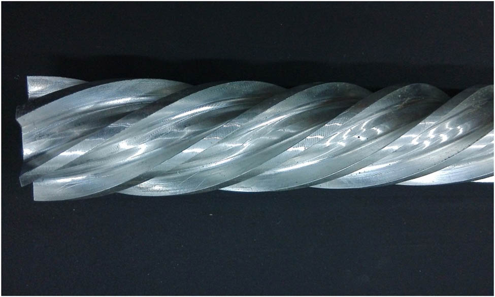
Picture of multi-start helical channel component.
Comparison of the main structural parameters of ETS
| Configuration and parameters | Value |
|---|---|
| ETS of HCCC | |
| Effective length (mm) | 1,000 |
| Inner tube ID (mm) | 50 |
| Inner tube thickness (mm) | 3 |
| Outer tube ID (mm) | 80 |
| Inner tube material | 304 stainless steel |
| Outer tube material | 304 stainless steel |
| Multi-start helical channel component | |
| Effective length (mm) | 1,000 |
| Width of fin (mm) | 5 |
| Depth of slots (mm) | 8.75 |
| Numbers of slots | 6 |
| Slot distance (mm) | 196 |
| Component OD (mm) | 48.5 |
| Component material | High strength aluminum alloy |

Picture of the ETS of HMSHC.
Finally, during the tests, the local temperature, pressure, and mass flowrate were all gathered by KEITHLEY-2700 data acquisition unit at interval of 5 s, and were saved in the computer for data processing. In each ETS, three important physical quantities of the average CHTCs, the outlet condensate mass flowrates (CMFRs), and the total steam condensation pressure drops (SCPDs) were separately obtained by using the conservation of mass and energy. Inside the HMSHC, performance evaluation factors of the average CHTCs and performance evaluation factors of the outlet CMFRs were introduced to evaluate the enhancement performance of steam condensation in the presence of NC gas nitrogen.
3 Experimental calculation and data processing
The inlet mass fraction of NC gas nitrogen is given by:
where
On the coolant side, the rate of heat absorption for the coolant in ETS is:
where
On the thermal fluid side, the rate of heat release from thermal fluid in ETS is:
where
The average heat transfer rate
By Newton’s law of cooling, the convective heat transfer coefficient
where
The ETS is a typical concentric-tube heat exchanger. If the fouling resistance is neglected, the average heat transfer rate
where
Finally, the condensation heat transfer coefficient
Using the method in literature [30], the error propagation analysis had been performed to evaluate the uncertainty of the main physical quantity. It was found that the uncertainties of the heat transfer rates were approximately ±7.00%, and the uncertainties of the average CHTCs were approximately ±10.00%.
4 System validation
First, in the following experimental conditions: inlet steam partial pressure P i,s = 0.3–0.7 MPa, inlet steam flowrates m i,s = 28–65 kg h−1, inlet NCGMFs ω i,n = 0–10%, inlet cooling water flowrates m i,cw = 2,500–4,000 kg h−1, the relative heat balance rate, the cooling water flow characteristics, and the steam condensation characteristics inside HCCC were investigated and verified.
4.1 Validation of relative heat balance rate
Only tests with the differences in the heat balance within ±10% were considered. At this point, the whole steam condensation system was considered to reach a stable state, and the experimental data were recorded. As displayed in Figure 6, the heat balance rate between them were within 10% error for more than 99% of all data.

Verification of heat balance rate.
4.2 Validation of cooling water flow characteristics
On the coolant side, the cooling water convection characteristics were compared with the existing correlations [31]. The experimental Nuexp obtained by the theoretical formula were compared with the predictive Nucal obtained by the correlations, validation is shown in Figure 7. The results showed that the deviations between the predictive Nucal and the experimental Nuexp were less than 10%, indicating that the test data collected by data acquisition unit are reasonable and reliable.

Verification of experimental Nuexp and predictive Nucal from the correlations.
4.3 Validation of steam condensation characteristics
On the thermal fluid side, the steam condensation characteristics were also compared with Caruso’s correlation [11]. The experimental Nuexp calculated by the theoretical formula were verified with the predictive Nucal from Caruso’s correlation, as shown in Figure 8. The results showed that the predictive Nucal were about 1.5–2.5 times of the experimental Nuexp. The main reason for the deviation is due to different experimental conditions: Caruso’s correlation was fixed with the test data inside the slightly inclined tube; however, the condenser tube in this study was horizontal with no inclination. Therefore, we need to establish a new criterion correlation according to the current situation.

Verification of experimental Nuexp and predictive Nucal of Caruso’s correlation.
Based on the test data, a new criterion correlation for the inlet steam Nus is proposed as follows:
Experimental range: inlet NCGMFs is 0 ≤ ω ≤ 10%, inlet steam/nitrogen mixture is 38,705 ≤ Rem ≤ 40,025, outlet condensate is 664 ≤ Rel ≤ 766, and gravity-controlled stratified region with dimensionless steam velocity is J s < 0.9, and Martinelli number X tt < 1. Descriptions of the stratified flow region controlled by gravity is given in ref. [32].
The comparative verification between the experimental Nuexp obtained by theoretical formula and the predictive Nucal obtained from equation (7) is shown in Figure 9. The results show that relative error between the experimental Nuexp and the calculative Nucal are less than 10% for all data. The R 2 value is 0.905 and the Std Error is 0.176, Separately.
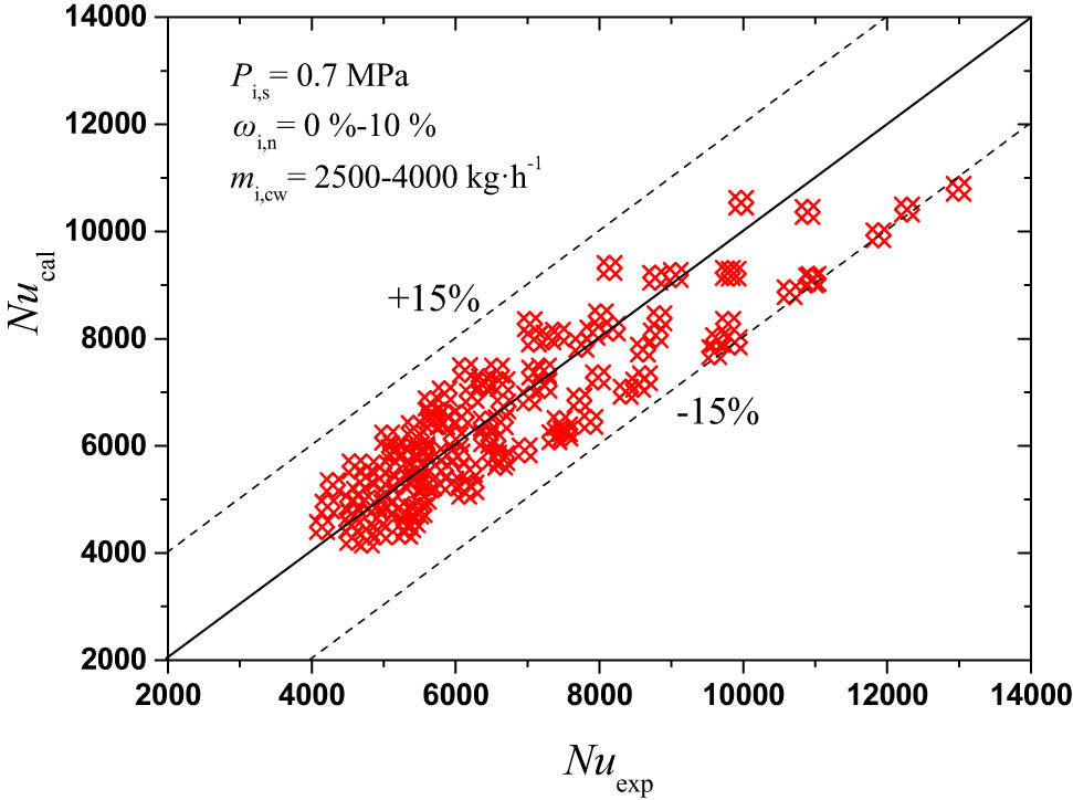
Verification of experimental Nuexp and predictive Nucal of new fitting correlation.
5 Experimental results and discussion
To reveal the internal mechanism of enhanced condensation heat transfer, taking steam condensation characteristics in the HCCC as a reference, steam condensation characteristics in HMSHC are experimentally investigated and discussed under the specific experimental conditions: inlet cooling water flowrates m i,cw = 2,500–4,000 kg h−1, inlet steam partial pressure P i,s = 0.7 MPa, inlet steam flowrate m i,s = 65 kg h−1, and inlet NCGMFs ω i,n = 0–10%.
5.1 Characteristics of the HCCC
In view of the symmetrical and nonuniform characteristics of the liquid film in the horizontal condenser tube in the axial and circumferential directions, the average steam condensation characteristics inside the HCCC were first investigated. Influence of inlet NCGMFs on average CHTCs for different cooling water flowrates is shown in Figure 10. Figure 11 presents the influence of inlet NCGMFs on the outlet CMFRs for different cooling water flowrates. Figure 12 indicates the influence of inlet NCGMFs on the total SCPDs for different cooling water flowrates.

Influence of inlet NCGMFs on average CHTCs for different cooling water flowrates.

Influence of inlet NCGMFs on outlet CMFRs for different cooling water flowrates.

Influence of inlet NCGMFs on overall SCPDs for different cooling water flowrates.
In Figures 10–12, taking the pure steam under rated condition as a reference, it can be concluded for a fixed steam flowrate and different inlet NCGMFs that when inlet nitrogen mass fraction is separately 2, 5, 7, and 10%, the average CHTCs decreases accordingly by 22, 30, 45, and 58%, severally, and the outlet CMFRs decreases correspondingly by 8, 11, 14, and 15%, respectively, and the overall SCPDs increase correspondingly by 7, 12, 17, and 20%, respectively. Moreover, in comparison to the pure steam, when the mass flowrate of the cooling water changes from 2,500 to 4,000 kg h−1 with every 500 kg h−1 increase, the average CHTCs approximately increase by 10%, and the outlet CMFRs increase correspondingly by 5%, and the overall SCPDs increase correspondingly by 6%. The results clearly indicated that all three physical quantities decreases in different degrees with the increment in inlet NCGMFs, and all the physical quantities increase with the increment in cooling water mass flowrates to varying degrees. The main reason of weakening steam condensation: the formation of nitrogen diffusion layer seriously restricts further condensation of the steam. That is to say, as the steam condenses gradually in the condenser tube, the nitrogen diffusion layer appears and becomes thicker and thicker along the axial direction, only passing through which by way of convection or diffusion steam can be condensed on the liquid film. The thermal resistance of nitrogen diffusion layer has become the primary factor to prevent further condensation of steam. Moreover, with the increment in inlet NCGMFs, steam condensation becomes more difficult. The strengthening measure is to enhance the gas–liquid disturbance in the condenser tube, to accelerate the removal of the condensate, and to thin or destroy the thickness of nitrogen diffusion layer which is the most important factor affecting the steam condensation characteristics.
5.2 Comparison of characteristics between HMSHC and HCCC
Next taking the HCCC as a reference, the steam condensation enhancement characteristics inside the HMSHC formed only by infixing a multi-start helical channel component into the condenser tube of HCCC mentioned earlier were experimentally investigated, and compared to that of the HCCC under the same experimental conditions. The comparison of the average CHTCs between the HMSHC and the HCCC under same experimental conditions is demonstrated in Figure 13. Figure 14 displays the comparison of the outlet CMFRs between the HMSHC and the HCCC under same experimental conditions. Figure 15 shows the comparison of the overall SCPDs between the HMSHC and the HCCC under the same experimental conditions.

Comparison of average CHTCs between HMSHC and HCCC under same experimental conditions.

Comparison of outlet CMFRs between HMSHC and HCCC under same experimental conditions.

Comparison of overall SCPDs between HMSHC and HCCC under same experimental conditions.
In Figures 13 and 14, it can be concluded by comparison that, under same experimental conditions, when the mass flowrate of the cooling water changes from 2,500 to 4,000 kg h−1 with an increment of 500 kg h−1, when inlet nitrogen mass fraction changes separately from 0 to 2, 5, 7, and 10%, as far as the relative ratio of the whole experimental range, the average CHTCs of the HMSHC is approximately 2.35 times as much as that of the HCCC, and the outlet CMFRs of the HMSHC is approximately 1.25 times as much as that of the HCCC. It is noticeable that the above two performance indicators of the HMSHC are significantly better than that of the HCCC under same experimental conditions. Similarly, in Figure 15, it can also be concluded by comparison that the overall SCPDs of the HMSHC is approximately 1.16 times as much as that of the HCCC. The reinforcement mechanism of the HMSHC as follows: the decrease in the steam-side equivalent diameter improves significantly the steam-side speed, and accelerates the removal of the condensate, and undoubtedly thins the thickness of nitrogen diffusion layer. The use of the multi-start helical channels changes the steam flow direction, and prolongs the time of steam condensation. The secondary circulation generated in the multi-start helical channels also strengthens the disturbance, and even destroys the thickness of nitrogen diffusion layer, which would greatly promote the further condensation of the steam ultimately under the comprehensive function of various factors. While the reason for the enlargement of the overall SCPDs inside HMSHC is mainly due to more steam condensation and higher friction pressure loss.
5.3 Performance evaluation factor of HMSHC
Finally, the performance evaluation factor was used to evaluate the comprehensive performance of the HMSHC in the above specific experimental scope. The performance evaluation factor
where the subscript “r” is the abbreviation of “reference”, here HCCC is taken as reference. The subscript “e” is the abbreviation of “enhancement”, here it refers to the HMSHC. The overall SCPDs between the inlet and outlet
Summary of steam condensation characteristics inside HMSHC and HCCC
| Characteristic | HCCC | HMSHC |
|---|---|---|
| Condensation type | Film condensation | Film condensation |
| Channel type of steam condensation | HCCC | HMSHC |
| Pressure of inlet steam (MPa) | 0.7 | 0.7 |
| Mass flowrates of inlet steam (kg h−1) | 65 | 65 |
| Equivalent diameter of steam channel (mm) | 50 | 10 |
| Specific mass flux of inlet steam (kg m−2 s−1) | 8.0 | 198 |
| Channel type of cooling water convection | Annular interlayer | Annular interlayer |
| Mass flowrates of cooling water (kg h−1) | 2,500–4,000 | 2,500/4,000 |
| Equivalent diameter of cooling water channel (mm) | 23 | 23 |
| NC gas type | Nitrogen | Nitrogen |
| Mass fractions of inlet NC gas (%) | 0, 2, 5, 7, and 10 | 0, 2, 5, 7, and 10 |
| Average CHTCs (W m−2 K−1) | 2.157–5.294 | 4.311–11.017 |
| Outlet CMFRs (kg h−1) | 24.887–32.933 | 30.271–38.381 |
| Overall SCPDs (MPa) | 10.455–31.019 | 13.464–33.961 |
| Performance evaluation factor of average CHTCs | — | 2.02 |
| Performance evaluation factor of outlet CMFRs | — | 1.08 |
6 Conclusion
To study the steam condensation characteristics in the HMSHC, under given steam pressure, cooling water mass flowrates, and NCGMFs conditions, the experimental investigation of steam condensation inside the HMSHC is performed, and the performance evaluation factor in the HMSHC were calculated, and the reinforcement mechanism of steam condensation in the HMSHC were analyzed. The main conclusions are as follows:
Although the symmetrical and non-uniform distribution characteristics of the liquid film in the axial and circumferential directions in the HCCC, seven thermocouples on each row along the direction of steam flow, a total of 40 T-type thermocouples in six rows make the local temperature measurement more reasonable and make the average heat transfer calculation of steam condensation more accurate, at the top, middle, and bottom part on the outer surface of the condenser tube and at the middle of the annular interlayer, respectively. It is found that the local temperature at the top part is higher than that at the bottom; however, the deviation gradually decreased along the direction of steam flow, especially at higher inlet NCGMFs.
In consideration of the complexity of steam/nitrogen condensation in the HMSHC, the experimental investigation of steam condensation in the HMSHC is based on that of steam condensation in the HCCC. Although the experimental Nuexp of steam/nitrogen condensation in the HCCC are quite different from the predicted Nucal of Caruso’s correlation, they are in good accordance with the predicted Nucal of the new fitting criterion in the study, less than ±15% for all data.
The degradation of three physical quantities clearly shows that nitrogen diffusion layer has a dramatic influence on steam condensation characteristics. In the HMSHC, taking the pure steam as a reference, the average CHTCs, the outlet CMFRs, and the overall steam condensations reduce by about 47, 12, and 22% when nitrogen mass fraction attains 10%, respectively. Inside the HCCC, by comparison to the pure steam, the average CHTCs, the outlet CMFRs, and the overall SCPDs reduce approximately by 58, 15, and 20%, separately. But for higher Rem, the gas–liquid interfacial shearing stress likely weakens the negative effect of the NC gas. In addition, increasing the cooling water flowrate can entirety promote steam condensation.
The comparison results of steam condensation revealed that, under the specific experimental scope, the average CHTCs of the HMSHC is approximately 2.35 times as much as that of the HCCC, and the outlet CMFRs of the HMSHC is approximately 1.25 times as much as that of the HCCC, and the overall SCPDs inside HMSHC are about 1.16 times of that inside HCCC. The performance evaluation factor (equations [13] and [14])) is introduced to evaluate the comprehensive performance of the HMSHC for the above specific experimental scope. The calculation results showed that the performance evaluation factor
-
Funding information: The Natural Science Foundation of China (Grant no. 51768054), the Innovation Foundation of Inner Mongolia University of Science and Technology (Grant no. 2016QDL-B24), and the Natural Science Foundation of Inner Mongolia Autonomous Region (Grant no. 2021MS05014), supported the current research work.
-
Author contributions: All authors have accepted responsibility for the entire content of this manuscript and approved its submission.
-
Conflict of interest: The authors state no conflict of interest.
References
[1] Ren B. Study on heat transfer characteristics of condensation inside horizontal tubes in presence of noncondensable gas. Ph.D. thesis. Shanghai, China: East China University of Science and Technology; 2015. p. 29–32.Suche in Google Scholar
[2] Xu HQ. Investigation of steam condensation heat transfer characteristics in the presence of noncondensable gases in a horizontal tube. Ph.D. thesis. Harbin, China: Harbin Engineering University; 2017. p. 46–68.Suche in Google Scholar
[3] Nolte G, Mayinger F. Condensation from steam-air mixtures in a horizontal annular flow channel. Exp Therm Fluid Sci. 1988;1:373–84.10.1016/0894-1777(88)90017-9Suche in Google Scholar
[4] Zhu AM, Wang SC, Sun JX, Xie LX, Wang Z. Effects of high fractional noncondensable gas on condensation in the dewvaporation desalination process. Desalination. 2007;214:128–37.10.1016/j.desal.2006.08.017Suche in Google Scholar
[5] Othmer DF. The condensation of steam. Ind Eng Chem. 2002;21:576–83.10.1021/ie50234a018Suche in Google Scholar
[6] Sideman S, Moalem D, Semiat R. Performance improvement of horizontal evaporator-condenser desalination units. Desalination. 1977;21:221–33.10.1016/S0011-9164(00)80319-7Suche in Google Scholar
[7] Nakamura H, Kondo M, Asaka H, Anoda Y, Tabata H, Obata H. Single U-tube testing and RELAP5 code analysis of PCCS with horizontal heat exchanger. In: Proceedings of NTHAS2 Second Japan-Korea Symposium on Nuclear Thermal Hydraulics and Safety. Fukuoka, Japan; 2000. p. 336–43.Suche in Google Scholar
[8] Wu T, Vierow K. Local heat transfer measurements of steam/air mixtures in horizontal condenser tubes. Int J Heat Mass Transf. 2006;49:2491–501.10.1016/j.ijheatmasstransfer.2006.01.025Suche in Google Scholar
[9] Caruso G, Giannetti F, Naviglio A. Experimental investigation on pure steam and steam–air mixture condensation inside tubes. Int J Heat Technol. 2012;30(2):77–84.10.18280/ijht.300211Suche in Google Scholar
[10] Caruso G, Di Maio DV, Naviglio A. Film condensation in inclined tubes with noncondensable gases: An experimental study on the local heat transfer coefficient. Int Commun Heat Mass Transf. 2013;45:1–10.10.1016/j.icheatmasstransfer.2013.04.010Suche in Google Scholar
[11] Caruso G, Vitale Di Maio D, Naviglio A. Condensation heat transfer coefficient with noncondensable gases inside near horizontal tubes. Desalination. 2013;309:247–53.10.1016/j.desal.2012.10.026Suche in Google Scholar
[12] Ren B, Zhang L, Xu H, Cao J, Tao ZY. Experimental study on condensation of steam/air mixture in a horizontal tube. Exp Therm Fluid Sci. 2014;58:145–55.10.1016/j.expthermflusci.2014.06.022Suche in Google Scholar
[13] Cheng FN, Dai RK, Wen JJ, Ying Z, Zeng M, Wang QW. Condensation in horizontal rectanglular channel. CIESC J. 2016;67:246–52.Suche in Google Scholar
[14] Xu H, Gu H, Sun Z. Forced convection condensation of steam in the presence of multicomponent noncondensable gases inside a horizontal tube. Int J Heat Mass Transf. 2017;104:1110–9.10.1016/j.ijheatmasstransfer.2016.09.031Suche in Google Scholar
[15] Shen SQ, Wang YX, Yuan DY. Circumferential distribution of local heat transfer coefficient during steam stratified flow condensation in vacuum horizontal tube. Int J Heat Mass Transf. 2017;114:816–25.10.1016/j.ijheatmasstransfer.2017.06.042Suche in Google Scholar
[16] Minkowycz WJ, Sparrow EM. Condensation heat transfer in the presence of noncondensables, interfacial resistance, superheating, variable properties, and diffusion. Int J Heat Mass Transf. 1966;9:1125–44.10.1016/0017-9310(66)90035-4Suche in Google Scholar
[17] Tang GH, Hu HW, Zhuang ZN, Tao WQ. Film condensation heat transfer on a horizontal tube in presence of a noncondensable gas. Appl Therm Eng. 2012;36:414–25.10.1016/j.applthermaleng.2011.10.058Suche in Google Scholar
[18] Takeda T, Ohwada A, Nakamura H. Measurement of non-condensable gas in a PWR small-break LOCA simulation test with LSTF for OECD/NEA ROSA Project and RELAP5 post-test analysis. Exp Therm Fluid Sci. 2013;51:112–21.10.1016/j.expthermflusci.2013.07.007Suche in Google Scholar
[19] Lee KY, Kim MH. Steam condensation in the presence of a noncondensable gas in a horizontal tube, evaporation, condensation and heat transfer. Republic of Korea: Korea Atomic Energy Research Institute/Pohang University of Science and Technology; 2011. p. 153–68.10.5772/21234Suche in Google Scholar
[20] Lee KY, Kim MH. Experimental and empirical study of steam condensation heat transfer with a noncondensable gas in a small-diameter vertical tube. Nucl Eng Des. 2008;238:207–16.10.1016/j.nucengdes.2007.07.001Suche in Google Scholar
[21] Ahn T, Kang J, Bae B. Steam condensation in horizontal and inclined tubes under stratified flow conditions. Int J Heat Mass Transf. 2017;141:71–87.10.1016/j.ijheatmasstransfer.2019.06.056Suche in Google Scholar
[22] Morteza KA, Zahra AL. Proposing new configurations for twisted square channel (TSC): Nanofluid as working fluid. Appl Therm Eng. 2016;108:709–19.10.1016/j.applthermaleng.2016.07.173Suche in Google Scholar
[23] Liang ZS, Sun J, Chau HK, Leong EI, Wu D, Chen GH, et al. Experimental investigation on the air-side flow and heat transfer characteristics of 3-D finned tube bundle. Int J Heat Mass Transf. 2019 Mar;131:506–16.10.1016/j.ijheatmasstransfer.2018.10.026Suche in Google Scholar
[24] Derby M, Lee HJ, Peles Y, Jensen MK. Condensation heat transfer in square, triangular, and semi-circular mini-channels. Int J Heat Mass Transf. 2011;55(1):187–97.10.1016/j.ijheatmasstransfer.2011.09.002Suche in Google Scholar
[25] Khan MZU, Uddin E, Akbar B, Akram N, Naqvi AA, Sajid M, et al. Investigation of heat transfer and pressure drop in microchannel heat sink using Al2O3 and ZrO2 nanofluids. Nanofluids. 2020;10(9):1796.10.3390/nano10091796Suche in Google Scholar PubMed PubMed Central
[26] Zhou J, Cao X, Zhang N, Yuan Y, Zhao X, Hardy D. Micro-channel heat sink: a review. J Therm Sci. 2020;29(6):1431–62.10.1007/s11630-020-1334-ySuche in Google Scholar
[27] Zheng D, Wang J, Chen Z, Baleta J, Sundén B. Performance analysis of a plate heat exchanger using various nanofluids. Int J Heat Mass Transf. 2020;158:119993.10.1016/j.ijheatmasstransfer.2020.119993Suche in Google Scholar
[28] Zheng D, Yang J, Wang J, Kabelac S, Sundén B. Analyses of thermal performance and pressure drop in a plate heat exchanger filled with ferrofluids under a magnetic field. Fuel. 2021;293:120432.10.1016/j.fuel.2021.120432Suche in Google Scholar
[29] Wang J, Li Y, Zheng D, Mikulčić H, Vujanović M, Sundén B. Preparation and thermophysical property analysis of nanocomposite phase change materials for energy storage. Renew Sustain Energy Rev. 2021;151:111541.10.1016/j.rser.2021.111541Suche in Google Scholar
[30] Kline SJ, McClintock F. Describing uncertainties in single-sample experiments. Mech Eng. 1953;75:3–8.Suche in Google Scholar
[31] Yang SM, Tao WQ. Heat Transfer. 3th edn. Beijing, China: Higher Education Press; 1998. p. 164–6.Suche in Google Scholar
[32] Palen JW, Breber G, Taborek J. Prediction of flow regimes in horizontal tube-side condensation. Heat Transf Eng. 1979;1(2):5–57.10.1080/01457637908939558Suche in Google Scholar
© 2021 Jianjun Wen et al., published by De Gruyter
This work is licensed under the Creative Commons Attribution 4.0 International License.
Artikel in diesem Heft
- Regular Articles
- Circular Rydberg states of helium atoms or helium-like ions in a high-frequency laser field
- Closed-form solutions and conservation laws of a generalized Hirota–Satsuma coupled KdV system of fluid mechanics
- W-Chirped optical solitons and modulation instability analysis of Chen–Lee–Liu equation in optical monomode fibres
- The problem of a hydrogen atom in a cavity: Oscillator representation solution versus analytic solution
- An analytical model for the Maxwell radiation field in an axially symmetric galaxy
- Utilization of updated version of heat flux model for the radiative flow of a non-Newtonian material under Joule heating: OHAM application
- Verification of the accommodative responses in viewing an on-axis analog reflection hologram
- Irreversibility as thermodynamic time
- A self-adaptive prescription dose optimization algorithm for radiotherapy
- Algebraic computational methods for solving three nonlinear vital models fractional in mathematical physics
- The diffusion mechanism of the application of intelligent manufacturing in SMEs model based on cellular automata
- Numerical analysis of free convection from a spinning cone with variable wall temperature and pressure work effect using MD-BSQLM
- Numerical simulation of hydrodynamic oscillation of side-by-side double-floating-system with a narrow gap in waves
- Closed-form solutions for the Schrödinger wave equation with non-solvable potentials: A perturbation approach
- Study of dynamic pressure on the packer for deep-water perforation
- Ultrafast dephasing in hydrogen-bonded pyridine–water mixtures
- Crystallization law of karst water in tunnel drainage system based on DBL theory
- Position-dependent finite symmetric mass harmonic like oscillator: Classical and quantum mechanical study
- Application of Fibonacci heap to fast marching method
- An analytical investigation of the mixed convective Casson fluid flow past a yawed cylinder with heat transfer analysis
- Considering the effect of optical attenuation on photon-enhanced thermionic emission converter of the practical structure
- Fractal calculation method of friction parameters: Surface morphology and load of galvanized sheet
- Charge identification of fragments with the emulsion spectrometer of the FOOT experiment
- Quantization of fractional harmonic oscillator using creation and annihilation operators
- Scaling law for velocity of domino toppling motion in curved paths
- Frequency synchronization detection method based on adaptive frequency standard tracking
- Application of common reflection surface (CRS) to velocity variation with azimuth (VVAz) inversion of the relatively narrow azimuth 3D seismic land data
- Study on the adaptability of binary flooding in a certain oil field
- CompVision: An open-source five-compartmental software for biokinetic simulations
- An electrically switchable wideband metamaterial absorber based on graphene at P band
- Effect of annealing temperature on the interface state density of n-ZnO nanorod/p-Si heterojunction diodes
- A facile fabrication of superhydrophobic and superoleophilic adsorption material 5A zeolite for oil–water separation with potential use in floating oil
- Shannon entropy for Feinberg–Horodecki equation and thermal properties of improved Wei potential model
- Hopf bifurcation analysis for liquid-filled Gyrostat chaotic system and design of a novel technique to control slosh in spacecrafts
- Optical properties of two-dimensional two-electron quantum dot in parabolic confinement
- Optical solitons via the collective variable method for the classical and perturbed Chen–Lee–Liu equations
- Stratified heat transfer of magneto-tangent hyperbolic bio-nanofluid flow with gyrotactic microorganisms: Keller-Box solution technique
- Analysis of the structure and properties of triangular composite light-screen targets
- Magnetic charged particles of optical spherical antiferromagnetic model with fractional system
- Study on acoustic radiation response characteristics of sound barriers
- The tribological properties of single-layer hybrid PTFE/Nomex fabric/phenolic resin composites underwater
- Research on maintenance spare parts requirement prediction based on LSTM recurrent neural network
- Quantum computing simulation of the hydrogen molecular ground-state energies with limited resources
- A DFT study on the molecular properties of synthetic ester under the electric field
- Construction of abundant novel analytical solutions of the space–time fractional nonlinear generalized equal width model via Riemann–Liouville derivative with application of mathematical methods
- Some common and dynamic properties of logarithmic Pareto distribution with applications
- Soliton structures in optical fiber communications with Kundu–Mukherjee–Naskar model
- Fractional modeling of COVID-19 epidemic model with harmonic mean type incidence rate
- Liquid metal-based metamaterial with high-temperature sensitivity: Design and computational study
- Biosynthesis and characterization of Saudi propolis-mediated silver nanoparticles and their biological properties
- New trigonometric B-spline approximation for numerical investigation of the regularized long-wave equation
- Modal characteristics of harmonic gear transmission flexspline based on orthogonal design method
- Revisiting the Reynolds-averaged Navier–Stokes equations
- Time-periodic pulse electroosmotic flow of Jeffreys fluids through a microannulus
- Exact wave solutions of the nonlinear Rosenau equation using an analytical method
- Computational examination of Jeffrey nanofluid through a stretchable surface employing Tiwari and Das model
- Numerical analysis of a single-mode microring resonator on a YAG-on-insulator
- Review Articles
- Double-layer coating using MHD flow of third-grade fluid with Hall current and heat source/sink
- Analysis of aeromagnetic filtering techniques in locating the primary target in sedimentary terrain: A review
- Rapid Communications
- Nonlinear fitting of multi-compartmental data using Hooke and Jeeves direct search method
- Effect of buried depth on thermal performance of a vertical U-tube underground heat exchanger
- Knocking characteristics of a high pressure direct injection natural gas engine operating in stratified combustion mode
- What dominates heat transfer performance of a double-pipe heat exchanger
- Special Issue on Future challenges of advanced computational modeling on nonlinear physical phenomena - Part II
- Lump, lump-one stripe, multiwave and breather solutions for the Hunter–Saxton equation
- New quantum integral inequalities for some new classes of generalized ψ-convex functions and their scope in physical systems
- Computational fluid dynamic simulations and heat transfer characteristic comparisons of various arc-baffled channels
- Gaussian radial basis functions method for linear and nonlinear convection–diffusion models in physical phenomena
- Investigation of interactional phenomena and multi wave solutions of the quantum hydrodynamic Zakharov–Kuznetsov model
- On the optical solutions to nonlinear Schrödinger equation with second-order spatiotemporal dispersion
- Analysis of couple stress fluid flow with variable viscosity using two homotopy-based methods
- Quantum estimates in two variable forms for Simpson-type inequalities considering generalized Ψ-convex functions with applications
- Series solution to fractional contact problem using Caputo’s derivative
- Solitary wave solutions of the ionic currents along microtubule dynamical equations via analytical mathematical method
- Thermo-viscoelastic orthotropic constraint cylindrical cavity with variable thermal properties heated by laser pulse via the MGT thermoelasticity model
- Theoretical and experimental clues to a flux of Doppler transformation energies during processes with energy conservation
- On solitons: Propagation of shallow water waves for the fifth-order KdV hierarchy integrable equation
- Special Issue on Transport phenomena and thermal analysis in micro/nano-scale structure surfaces - Part II
- Numerical study on heat transfer and flow characteristics of nanofluids in a circular tube with trapezoid ribs
- Experimental and numerical study of heat transfer and flow characteristics with different placement of the multi-deck display cabinet in supermarket
- Thermal-hydraulic performance prediction of two new heat exchangers using RBF based on different DOE
- Diesel engine waste heat recovery system comprehensive optimization based on system and heat exchanger simulation
- Load forecasting of refrigerated display cabinet based on CEEMD–IPSO–LSTM combined model
- Investigation on subcooled flow boiling heat transfer characteristics in ICE-like conditions
- Research on materials of solar selective absorption coating based on the first principle
- Experimental study on enhancement characteristics of steam/nitrogen condensation inside horizontal multi-start helical channels
- Special Issue on Novel Numerical and Analytical Techniques for Fractional Nonlinear Schrodinger Type - Part I
- Numerical exploration of thin film flow of MHD pseudo-plastic fluid in fractional space: Utilization of fractional calculus approach
- A Haar wavelet-based scheme for finding the control parameter in nonlinear inverse heat conduction equation
- Stable novel and accurate solitary wave solutions of an integrable equation: Qiao model
- Novel soliton solutions to the Atangana–Baleanu fractional system of equations for the ISALWs
- On the oscillation of nonlinear delay differential equations and their applications
- Abundant stable novel solutions of fractional-order epidemic model along with saturated treatment and disease transmission
- Fully Legendre spectral collocation technique for stochastic heat equations
- Special Issue on 5th International Conference on Mechanics, Mathematics and Applied Physics (2021)
- Residual service life of erbium-modified AM50 magnesium alloy under corrosion and stress environment
- Special Issue on Advanced Topics on the Modelling and Assessment of Complicated Physical Phenomena - Part I
- Diverse wave propagation in shallow water waves with the Kadomtsev–Petviashvili–Benjamin–Bona–Mahony and Benney–Luke integrable models
- Intensification of thermal stratification on dissipative chemically heating fluid with cross-diffusion and magnetic field over a wedge