Investigation on subcooled flow boiling heat transfer characteristics in ICE-like conditions
-
Xiaoyu Hu
 ,
Shuzhan Bai
and
Ke Sun
,
Shuzhan Bai
and
Ke Sun

Abstract
The increasing demand of cooling in internal combustion engine (ICE) may require the shift of heat removal method from traditional single phase liquid convection to subcooled flow boiling in order to fulfill the desired functional temperature. Thus, the characteristics of subcooled flow boiling heat transfer should be studied exclusively considering the practical conditions in ICEs. Accordingly, in this article, subcooled flow boiling experiments were conducted in a rectangular channel using 50/50 volume mixture of ethylene glycol and water coolant (EG/W) as working fluid. Aluminum and cast iron surfaces were selected as the heated surfaces to simulate the material of cylinder head in gasoline and diesel engines, respectively. Experimental results showed a trend that the aluminum surface had a better performance than the cast iron surface in terms of heat transfer coefficient in the boiling region. The difference between these two surfaces was concluded as results of different surface thermophysical properties. A modified wall heat flux model was proposed based on the power-type addition method. The proposed model modified the nucleation boiling contribution by introducing a new parameter which accounts for the influence of thermophysical properties of heated surface on the boiling process. Thus, one such modified model could be useful for practical engine cooling applications.
1 Introduction
Engine downsizing and strengthening is one of the important technical solutions to deal with increasingly strict fuel consumption and emission regulations [1]. However, an evitable issue associated with these techniques is the enhanced thermal load in internal combustion engine (ICE) cylinder head, which requires to establish optimal cooling strategies. A great amount of heat transfer augment techniques have been reported for decades, such as extended surfaces [2,3], boiling [4,5], ferrofluids [6], etc. Among these techniques, subcooled flow boiling heat transfer has been proved to be effective and beneficial to enhance heat transfer, which is largely due to its high heat dissipation rate under relatively small change in wall temperature. This benefit could help enhancing the heat transfer rate in the compact space of ICE cylinder head without essential changes in its architecture. However, the boiling process is extremely complex and contains many different phenomena, such as bubble nucleation, growth, detachment, and collapse, of which the process is still not fully understood yet [7,8]. Therefore, from the point of view of designing advanced engine cooling system, prediction of heat flux through coolant passage wall of ICEs is important and requires the application of empirical or semi-empirical correlations.
One such widely applied model in ICE industry was proposed by Chen [9], in which the overall heat transfer is governed by a combined effect of both forced convection component q sp and nucleate boiling component q nb. Two factors, the enhancement factor F and the suppression factor S that is as a function of flow Reynolds number, were defined taking into account the convective heat transfer enhancement by bubble agitation and the flow suppression effect on the nucleation boiling, respectively.
Several modifications have been made based on the investigation of subcooled flow boiling heat transfer to further improve the accuracy of Chen model in its application to ICE industry. As proposed by Steiner et al. [10], the suppression factor in Chen model was calibrated for saturated boiling and is insensitive to local parameters such as wall superheat and wall shear stress, which could cause deviations in application for subcooled flow boiling conditions. Then, a modified model was proposed to improve Chen’s superposition method by taking into account the impact of the flow-induced suppression and subcooling. As stated by Torregrosa et al. [11], the Chen model fails in boiling regimes for low velocities and subcooling, which is largely due to the significant influence of Prandtl number on suppression factor. More recently, Chen et al. [12] made a modification on the enhancement and suppression factors of the Chen model by introducing a non-dimension boiling number into them, and the predictions of this modified correlation coincides well with the subcooled flow boiling experimental data. Although Chen model has been exclusively used in ICE industry [13,14,15], its application to ICE cooling system design is not totally straightforward. For one thing, Chen model is mainly used in gasoline engines, but it may not be applicable to diesel engines because the Chen model overestimates the subcooled flow boiling heat flux of cast iron heated surfaces under high wall superheat [16]. The other is the difficulty in defining an effective hydraulic diameter and velocity scale for the cooling passage due to its complex architecture [10]. Therefore, an appropriate correlation considering the above issues is still required.
A more general form of the above strategy is the so called power-type addition model or asymptotic model. This kind of model mainly focuses on the component with greater influence regarding the convective and nucleate boiling components, which could connect the overall flow boiling phenomena with the more dominant mechanism in these two regions as well as assure a smooth transition in between.
where n is an empirical constant to be determined from the experimental data. In particular case of n = 1, it becomes the simple additive model similar to Chen model. The model given in equation (2) has the advantage that the researchers can incorporate the set of correlations which best estimate their problem for two contributions of forced convection and nucleation components.
Ramstorfer et al. [17] proposed a new type of power-type addition correlation adopting only Rohsenow saturation pool boiling type model [18] in its q nb. The advantages of this type of model are that first, it eliminates the dependence of structure parameters on calculating nucleation boiling term; second, it could reasonably account for the effect of fluid–solid interaction on boiling heat transfer. Similar method was adopted by Hua et al. [16]. According to the authors, the prediction results were sensitive to empirical constants C sf and γ, and these constants should be derived from the experimental results of exactly the same surface–fluid combination.
Consequently, there is a great interest in applying such a power-type addition model into ICE coolant jacket’s design considering its accuracy and independence on structure parameter. However, proper empirical constants in this type of model for the fluid–solid combination of 50/50 EG/W and aluminum or cast iron is not yet available in literature. Moreover, reprehensive subcooled flow boiling experimental data, especially that of 50/50 EG/W on cast iron heater surface is not sufficient to support in developing a generally improved model beyond the models mentioned above. Therefore, the objective of this work is to carry out subcooled flow boiling experiments under conditions that are similar to practical ICE operating conditions and construct an appropriate power-type addition model for future more advanced ICE engine coolant passage design.
One of the unique characteristics of coolant subcooled boiling in the cylinder head regions in ICEs is that boiling generally occurs only on the cooling channel side facing the flame plate because of the one-sided heating condition. Accordingly, in this study, subcooled flow boiling experiments were conducted in a one-side heated rectangular channel using 50/50 EG/W as working fluid. Aluminum and cast iron were employed as heater surfaces to simulate the material of gasoline and diesel engine cylinder head, respectively. Considering its practical conditions in ICEs, the experimental conditions of inlet temperature, bulk velocity, and system pressure ranged from 70 to 90°C, 0.25–1 m/s, and 1–2 bar, respectively. Finally, a subcooled flow boiling correlation was proposed to characterize the effect of heated surface material on flow boiling heat transfer.
2 Experimental setup
2.1 Experimental apparatus
The experiment system was built accordingly to investigate the subcooled flow boiling heat transfer in the cooling passages for cylinder head in ICEs. A schematic of the whole system is shown in Figure 1. The closed flow circulating system consists of storage tank, pump, flowmeter, heating apparatus, heat exchanger, and rectangular test section. The storage tank with a capacity of 150 L was designed to maintain a stable bulk fluid temperature. Four immersion heaters with total maximum power of 4 kW were installed at the bottom of the storage tank. The heaters were controlled by a PID controller so as to achieve and maintain certain bulk fluid temperature. Likewise, a solenoid valve connected to high pressure nitrogen was mounted on the top of the storage tank to adjust the pressure in the loop by the PID controller. Additionally, the circuit was equipped with a variable speed pump to determine flow rate across the test section.

Schematic of boiling system.
A photo of the real flow boiling test section can be seen in Figure 2. The horizontal rectangular test section, of 300 mm length and with 38 mm × 48 mm cross-sectional dimensions, located at 2,000 mm downstream of a stainless steel rectangular tube, which was to ensure the flow in the test section was fully developed is shown in Figure 3. The test specimen with dimensions of 90 mm × 10 mm was placed on the bottom surface of the test section and was located 110 mm downstream of the test section inlet. The test specimen was heated by seven heating rods inserted at the bottom of the testing surfaces which can supply a maximum power of around 7 kW. As shown in Figure 4, seven K-type thermocouples with diameter of 1.0 mm were arranged below the test specimen along the vertical direction in two rows, where three thermocouples were in the upper row and the other four were in the lower row. The thermocouple probes were inserted to reach the width-wise centerline below the testing surface. The heating surface temperature during the experiment was obtained based on the thermocouple readings and Fourier’s thermal conduction equation. The distance between the upper row and the test section surface is 3 mm and the distance between upper and lower rows is 5 mm. Since PTFE (polytetrafluoroethylene) was coated on the surrounding of test samples to minimize thermal diffusion, most of the heat can only be transferred in the vertical direction (i.e., 1-D) through the thickness of the test specimen.

Photo of the test section.
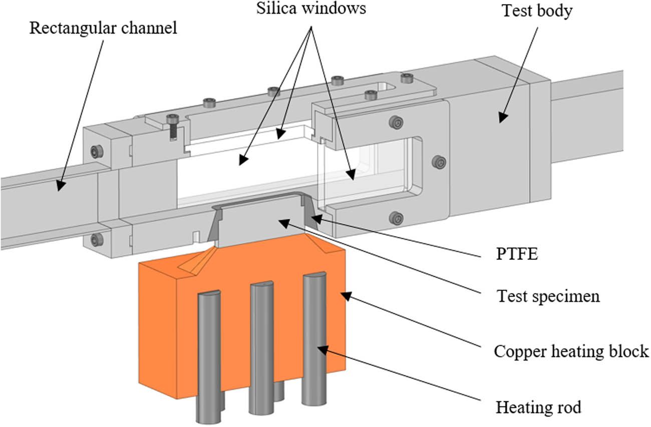
Details of test section.

Location of thermocouples and dimension of test specimen.
2.2 Experimental procedures
Before the formal testing, the bulk fluid was heated close to its boiling point (around 95°C) for several hours to remove the dissolved gas in the fluid. Besides, subcooled flow boiling heat transfer experiment was continuously running for more than 100 h before generating any experimental data in order to minimize the effect of heater surface morphology on boiling heat transfer [19]. The experimental range of inlet temperature, bulk velocity, and system pressure were set as 70–90°C, 0.25–1 m/s, and 1–2 bar, respectively. In each experimental condition, the test surface was heated from low heat flux to high heat flux and the data were taken 20 min after the system reached thermally steady state. Heat flux q and surface temperature T w are calculated as follows:
where T 1 and T 2 are average temperatures of the upper and lower thermocouple rows, respectively. H 1 (3 mm) and H 2 (5 mm) are the distances from the heated surface to the upper thermocouples row and the distance between the upper and lower thermocouple rows, as shown in Figure 4. k is the thermal conductivity of the test specimen.
2.3 Experimental uncertainties
The experimental errors of the variables were mainly caused by the accuracy of sensors, manufacturing tolerances, the layout of thermocouples, undesired heat losses, and functions to calculate the indirect variables. Before the experiment, all the thermocouples and corresponding data acquisition system were calibrated according to the thermal conditions between ice and saturation temperature of water. For uncertainties of indirect measurement such as heat flux, error propagation equation (6) was adopted for the calculation. All the calculated and measured uncertainties are listed in Table 1.
where
Experimental uncertainties
| Parameters | Uncertainties |
|---|---|
| Bulk temperature | 0.1°C |
| Bulk velocity | 0.022 m/s |
| Pressure | 1,500 Pa |
| Thermocouple location | 0.15 mm |
| Thermocouple temperature | 0.1°C |
| Heat flux | ≤11.2% |
2.4 Fluid thermophysical properties
The thermophysical properties of bulk liquid are required in the data reduction and analysis of this study. These properties are usually a function of the temperature, and the effective thermophysical properties of EG/W mixtures are calculated based on the values of pure water and ethylene glycol, and also the concentration of ethylene glycol in the mixtures. The density, specific heat capacity, thermal conductivity, and dynamic viscosity of pure liquids and mixtures were evaluated by semi-empirical equations as suggested in refs. [20,21,22].
3 Experimental result and discussion
3.1 Single-phase heat transfer
Before the subcooled flow boiling heat transfer experiment, a series of single-phase heat transfer experiments were carried out to validate the experimental setup and study the heat transfer characteristics of one-side heated rectangular channels. The prediction of convective heat flux q sp was calculated as follows:
where h sp is the single-phase heat transfer coefficient calculated from Dittus–Boelter equation [23]. T w and T b are wall temperature and bulk temperature, respectively.
where Rel and Prl are the liquid Reynolds number and Prandtl number, respectively, as can be seen in equations (9) and (10). k l is the thermal conductivity of the bulk liquid. All these values are evaluated at bulk temperature.
where ρ l, u b, μ l, and c p,l are bulk density, velocity, dynamic viscosity, and specific thermal capacity, respectively. D h is the hydraulic diameter of the test channel, which can be calculated as follows:
where A is the cross-sectional area of the channel and P e is the wetted perimeter of the channel. In this article, the D h equals to 42.4 mm.
The comparative results between experimental data and predicted values can be seen in Figure 5(a). It is shown that the Dittus–Boelter equation underpredicted the heat flux value, and this trend is in consistence with previous literatures [14,23]. The range of validation of Dittus–Boelter equation can be summarized as smooth pipes, hydraulically and thermally developed flow. Obviously, the experimental conditions in this article do not satisfy the validity criteria. As for this article, the heated surface is located downstream from the duck inlet. This would lead to an enhancement in heat transfer coefficient, since the bulk fluid reaching to the heated surface would be cooler than that of the simultaneously developing flow (fluid dynamic boundary layer and thermal boundary layer developed in the meantime) from which the Dittus–Boelter equation was proposed [23]. As a result, a modified equation was correlated based on the experimental data:

Comparison of experimental convective heat flux with predictions: (a) Dittus–Boelter correlation (b) modified Dittus–Boelter correlation.
The comparison between the experimental heat flux and predictions by modified equation is shown in Figure 5(b). the maximum deviation is within ±10%, which means the modified equation could well predict the convective heat transfer coefficient of this apparatus.
3.2 Subcooled flow boiling heat transfer
For the cooling system of ICEs, coolant temperature, velocity, and operation pressure are important control variables. As a result, the effect of these parameters on subcooled flow boiling heat transfer is discussed in more detail.
To investigate the effect of subcooling on subcooled flow boiling heat transfer, boiling curves at constant velocity and system pressure (u b = 1.0 m/s and P = 1.0 bar) are presented at various inlet temperatures from 70 to 90°C, as shown in Figure 6. It can be seen that, with the increase in subcooling, the onset of boiling (ONB) is delayed since the wall temperature is decreased with an increase in subcooling at a given heat flux. The boiling curves become steep after the ONB, which implies that the heat transfer coefficient is increased with the boiling process. In this partially developed boiling region (PDB), the heat transfer is determined by forced convection and nucleate boiling simultaneously, and the boiling curves of lower inlet temperature would be shifted to the left. But as the heat flux keeps increasing, the flow boiling comes into fully developed boiling region (FDB) where the agitation of generated bubbles is so vigorous that the effect of macro-forced convection disappears, and the boiling curves merge into an asymptote.

Effect of bulk subcooling on subcooled flow boiling heat transfer (u b = 1.0 m/s and P = 1.0 bar).
Figure 7 presents the effect of velocity on subcooled flow boiling at constant inlet temperature and system pressure (T in = 80°C and P = 1.0 bar) at various velocities from 0.25 to 1.0 m/s. With the increase in bulk velocity, the convective heat transfer coefficient increases, leading to higher boiling curve in PDB region since in this region the overall heat flux is largely dependent on forced convection. But this dependence disappears when the boiling goes into FDB region, where the boiling curves converge into the nucleation boiling curve. During boiling process, the bubble behavior, such as nucleation, growth, and departure, is strongly governed by the thermal boundary layer whose thickness decreases with the increase in bulk velocity [24]. As a result, increased bulk velocity would suppress the boiling process and finally lead to a delay on ONB and convergence to FDB for high bulk velocity cases.

Effect of bulk velocity on subcooled flow boiling heat transfer (T in = 80°C and P = 1.0 bar).
The boiling curves at different system pressures are plotted in Figure 8. These data were obtained at constant inlet temperature of 90°C, bulk velocity of 0.25 m/s, and various system pressures of 1.0, 1.5, and 2.0 bar, at the saturation temperature of 107.8, 119.9, and 129.3°C, respectively. It exhibits that, the effect of system pressure on single-phase heat transfer is considerably small, and the boiling curves at different pressures seem to follow a similar development pattern. However, the ONB is delayed with the increase in system pressure, which is mainly caused by the enhanced saturation temperature of the 50/50 EG/W mixture.
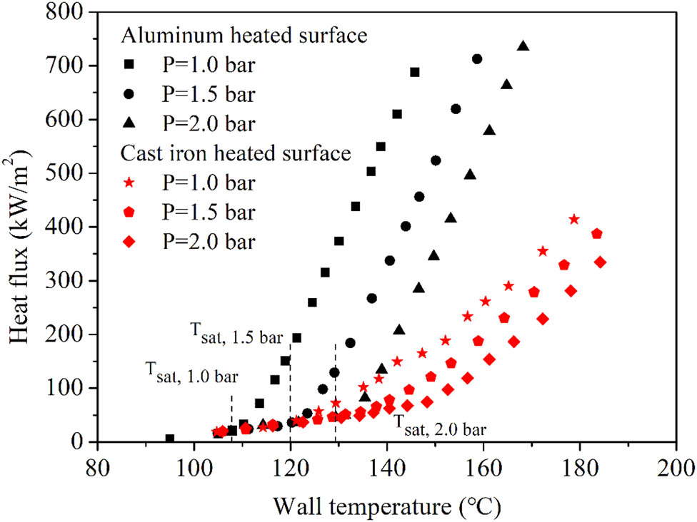
Effect of system pressure on subcooled flow boiling heat transfer (T in = 90°C and u b = 0.25 m/s).
The material of engine cylinder head is mainly aluminum or cast iron, and its influence on boiling heat transfer is shown in Figures 6–8. It can be seen that: (1) In the single-phase flow heat transfer area, the heated surface material has little effect on the heat transfer. In this area, the heat transfer effect is mainly affected by the flow and fluid physical parameters. (2) The boiling curves of aluminum and cast iron heated surfaces obey the similar law: under the same experimental conditions, as the inlet temperature and fluid velocity increase, the heat flux in the PDB increases. While in the FBD, the boiling heat transfer curves finally converge to nucleate boiling curves. In addition, as the system pressure increases, the ONB point is delayed. (3) In the boiling heat transfer area, under the same experimental conditions, the heat flux of the aluminum heated surface is higher than that of the cast iron heated surface, and this trend is more pronounced at low inlet temperature and fluid velocity conditions. It can be seen that for the design of the coolant passages of the engine cylinder head, in the area where single-phase flow heat transfer mechanism dominates, the effect of the cylinder head material on the heat transfer could be ignored; but in the area with high wall superheat where nucleate boiling heat transfer is the main mechanism, the difference in boiling heat transfer performance caused by different materials must be considered.
The difference of boiling heat flux between these two surfaces is concluded as results of different surface thermophysical properties, such as thermal conductivity. On the heated surface, vapor bubble generating centers are places of intensive heat removal, with the local heat flux being much higher than the average value. Therefore, the time-average temperature near the active vapor bubble generating center in the surface layer of a heated surface is lower than that on the rest of the surface. This will cause the overall temperature of the heating surface to decrease, which can obtain a greater heat transfer coefficient than single-phase heat transfer. Moreover, due to the uneven temperature distribution, heat would be transferred inside the surface layer from the free surface of the uncovered bubble to the vicinity of the nucleation center [25,26]. The thermal conductivity of the heated surface material is the key factor that determines its internal heat conduction. It can be predicted that the higher the thermal conductivity of the heated surface, the stronger the internal heat conduction from the free surface to the nucleation center, and thus better heat transfer efficiency.
From the perspective of bubble dynamics, the evaporation of the micro-liquid layer at the bottom of the bubble is the main mechanism of boiling heat transfer, and its contribution to the entire bubble volume accounts for 30–70% [27]. In the process of bubble growth, due to the evaporation of the micro-liquid layer, the temperature of the nearby heating surface will decrease. For the surface with high thermal conductivity, the heat conduction from the surrounding free surface to the vicinity of the nucleation point is easier than that of the surface with low thermal conductivity, and the temperature change around the nucleation point caused by evaporation is smaller. In other words, for high thermal conductivity heated surface, the bubble micro-liquid layer can supply more heat to bubble growth. Therefore, the heated surface with high thermal conductivity can obtain better boiling heat transfer performance.
4 Subcooled flow boiling correlation
4.1 Comparison between experimental data and predictions
As discussed previously, the power-type addition model proposed by Ramstorfer et al. [17] is attractive for the application in ICE coolant system design, as this model could reasonably account for the effect of fluid–solid combination on subcooled flow boiling heat transfer and no local input related to channel size or velocity is required. As a result, this type of model was chosen as reference model to make a comparison between the predicted and the experimental data of this article.
Ramstorfer et al. [17] conducted subcooled flow boiling experiment using 40/60 EG/W bulk fluid and cast iron heated surface combination. The experiment was carried out in a vertical channel under 3.4 bar system pressure, at 43°C subcooling, and at various bulk velocities. An asymptotic type model was proposed by correlating the experimental data, which is presented as follows:
where q conv is the convective heat flux and q nb is the nucleate heat flux. The natural convective heat transfer should be considered for the cases with very low velocity.
where q sp is the forced convective heat flux and q nc is the natural convective heat flux.
where the Grashof number Gr and f 1(Pr l) are given as follows:
where g is the gravitational acceleration, L is the length of the heated surface, and β l is the coefficient of thermal expansion.
The nucleate heat flux is calculated using the Rohsenow pool boiling equation [18].
where h lg is latent heat and ρ g is the density of vapor. C sf = 0.0172 and γ = 0.9 were suggested for the combination of 40-60 EG/W and cast iron.
Hua et al. [16] carried out subcooled flow boiling experiment in a horizontal rectangular channel heated with cast iron test sample using water as fluid. The experimental conditions of bulk temperature, bulk velocity, and system pressure were 70–90°C, 0.2–2 m/s, and 1–3 bar, respectively. The model is written as:
The term q nb is calculated based on equation (19) with C sf = 0.046 and γ = 0.624.
Moreover, Hua et al. [16] proposed a new correlation for water and aluminum heated surface combination based on the experimental data in ref. [10], which was conducted in a horizontal rectangular channel with aluminum heated surface and water as fluid. The correlations are given as follows:
where the q sp term is obtained from standard Dittus–Boelter equation. The q nb term is calculated from equation (19) with C sf = 0.0248 and γ = 0.613.
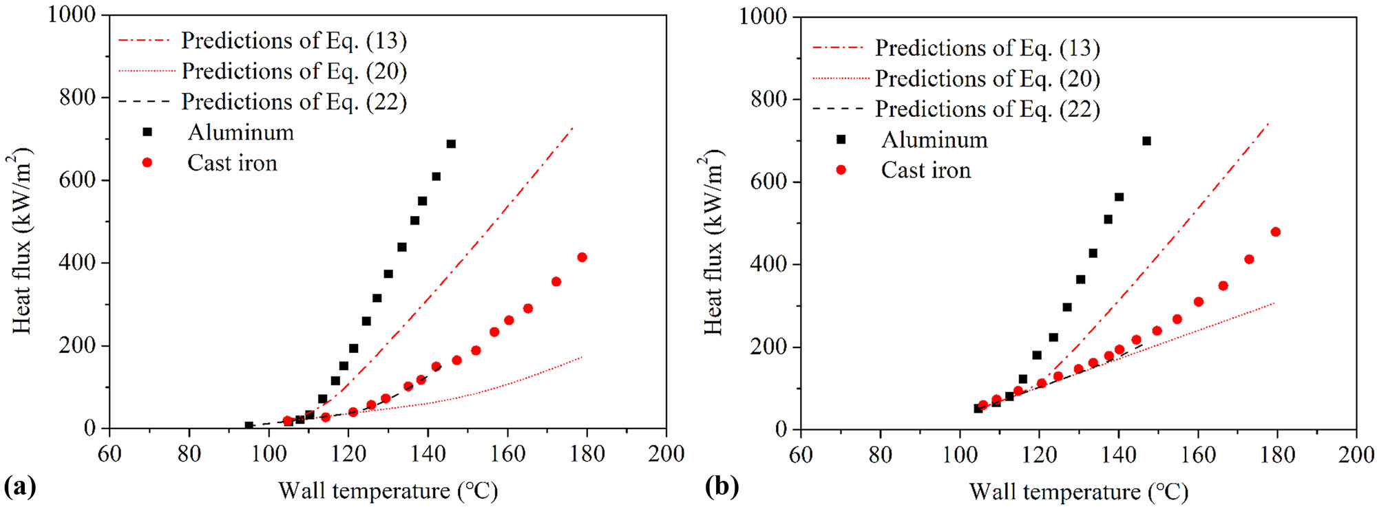
Comparisons have been made between the experimental data of this article and the predictions of the above proposed equations. The forced convection term in these equations was obtained from equations (7) and (12). Equations (13) and (20) were adopted to predict the heat flux value of cast iron heated surface, and equation (22) for aluminum surface.
Some representative comparison results between the predicted and experimental data are shown in Figures 9–12. It can be seen that, for particular measurement conditions considered here, the performance of the reference models is unreasonable, with a deviation larger than ±30% in high wall superheat region, especially for low bulk subcooling and velocity conditions. The main reason is that the empirical parameters C sf and γ in these equations are derived from experimental data of different solid–liquid combinations from this research. Equation (13) is based on the subcooled flow boiling heat transfer data of the cast iron and the 40/60 EG/W. For the same heated surface, the boiling heat transfer performance of 40/60 and 50/50 EG/W is not much different [28]. However, the heated test sample in the literature is a cylindrical heating rod with a diameter of 12 mm wrapped with a layer of cast iron, and its effusivity value (ρck, the product of density, specific heat capacity, and thermal conductivity) is higher than that of the cast iron heated block used in this research. Experimental studies have shown that the heated surface with a large effusivity value has a greater boiling heat transfer performance [7]. Therefore, the predicted value of heat flux in equation (13) is greater than the experimental value in this article. As for equations (20) and (22), these equations are derived for prediction of water subcooled heat transfer. And the influence of fluid physical parameters on boiling process is somewhat different for pure water and EG/W mixtures. Thus, the unmatched empirical parameters lead to large deviation in these reference models.
Comparison of heat flux between predicted and experimental data at T in = 90°C and P = 1 bar. (a) u b = 0.25 m/s and (b) u b = 0.5 m/s.

Comparison between experimental data of cast iron heated surface with predictions of equation (13).

Comparison between experimental data of cast iron heated surface with predictions of equation (20).

Comparison between experimental data of aluminum heated surface with predictions of equation (22).
4.2 Modified correlation
To develop a comprehensive subcooled flow boiling model, the nucleation boiling heat transfer model is modified initially. In order to reflect the influence of the thermos-properties of the heated surface on the subcooled flow boiling heat transfer, the Rohsenow pool boiling heat transfer model is modified. The main concept of Rohsenow’s method is that the heat transfers from the wall directly to the liquid with an increased heat transfer rate due to the agitation of liquid by the departing vapor bubbles. Based on this logical explanation of the boiling heat transfer mechanism, the usual type of convective heat transfer equation was used:
Where Nu b is the bubble Nusselt number, Reb is the bubble Reynolds number, and C is an empirical constant. Equation (23) can be written in the final form as:
It should be pointed out that the nucleate boiling curve of subcooled flow boiling is substantially different from that of pool boiling curve, according to the comparison of experimental results of subcooled flow boiling and pool boiling with the same heated surface [29]. In subcooled flow boiling, due to the influence of flow, the gradient of the thermal boundary layer near the wall is larger. Thus, the bubble characteristics in the subcooled flow boiling process will be different from the pool boiling, which will eventually lead to different disturbances of the liquid near the wall caused by generated bubbles. Therefore, it is necessary to re-establish the relationship between the dimensionless factors in equation (23).
Since only one fluid 50/50 EG/W is considered in this research, its Prandtl number is influenced only by the system pressure. Thus, the relationship between the dimensionless wall temperature and the heat flux of two heated surfaces was initially accessed under various system pressure conditions, as shown in Figure 13. Note that all the data used here were derived from the FDB region where the nucleate boiling heat transfer is the main heat transfer mechanism. It can be seen that m = 0.75 can well fit the data of the two heated surfaces.

The relationship between dimensionless wall temperature and heat flux.
In order to reflect the influence of the thermophysical properties of the heated surface on the boiling heat transfer, the following parameter is adopted accordingly:
where c p, k, and ρ are specific heat capacity, thermal conductivity, and density, respectively, and subscripts l and s refer to liquid and heated surfaces, respectively.
The C sf in equation (24) is set to account for the effect of fluid–solid interaction on boiling heat transfer. According to published references [7,25], ω has an exponential relationship with the boiling heat flux. Thereby, the authors now define C sf = Cω a . Thus, the equation (24) can be transformed into:
where C = 3.62 and a = 1.86 yield the best fit to the experimental data. The final nucleate boiling equation is given as follows:
The comparison between the predicted results of equation (27) and the experimental data of nucleate boiling is shown in Figure 14. It can be seen that the maximum deviation of the predicted results is within ±20%, indicating that the proposed nucleate boiling heat transfer model can well reflect the influence of thermophysical parameters of heated surface on boiling heat transfer.

Comparison between experimental data and predictions of the modified nucleation model.
For obtaining the final subcooled flow boiling heat transfer model, the power-type addition method in the literature [17] is adopted:
where b is the parameter that needs to be fitted. q sp is the heat flux of the single-phase flow heat transfer, calculated by equations (7) and (12); q nb is the heat flux of nucleate boiling, calculated by equation (27).
The final fitting shows that b = 6.5 can well predict the experimental data in this article. The comparison between the predicted value of the equation (28) and the experimental value is shown in Figure 15. It is shown that prediction results agree with the experimental data very well with the maximum deviation less than 20%.

Comparison between experimental data and predictions of modified subcooled flow boiling model.
5 Conclusion
Subcooled flow boiling heat transfer model is important for ICE cylinder head design. The present study reports the subcooled flow boiling experiment of 50/50 EG/W in a horizontal rectangular channel with a flat plane heated surface of aluminum and cast iron. The experiment was conducted under the condition similar to that of practical ICE applications, aiming to simulate the flow boiling characteristics in the real cooling passages of a cylinder head in ICEs. The main concluding remarks are as follows:
The effects of operation conditions, bulk temperature, bulk velocity, and system pressure, on subcooled flow boiling heat transfer are similar for aluminum and cast iron heated surfaces. And under same system pressure, the flow boiling curves of different bulk temperatures and velocities tend to converge to an asymptote, which implies in this region that the effect of these operation parameters disappears.
Besides above similarities, the aluminum surface had a better performance than the cast iron surface in terms of heat transfer coefficient in the boiling region. The difference between these two surfaces is concluded as results of different surface thermophysical properties.
A modified wall heat flux model is proposed based on the power-type addition method. The proposed model modifies the nucleation boiling contribution by introducing a new parameter which accounts for the influence of thermophysical properties of the heated surface on the boiling process. The comparison with experimental data shows good agreement indicating that the proposed model could help to improve the design of ICE cylinder head.
-
Funding information: This work was supported by the National Key Research and Development Project of China (Grant No. 2017YFB0103504) and National Natural Science Foundation of China (Grant No.51576116).
-
Conflict of interest: The authors state no conflict of interest.
Nomenclature
Latin symbols
- A
-
Cross-sectional area of the duck, m2
- C p
-
specific heat, J/kg K
- C sf
-
fluid–solid combination constant
- D h
-
hydraulic diameter, mm
- g
-
gravitational acceleration, m/s2
- G
-
mass flow rate, kg/m2 s
- h fg
-
latent heat, J/kg
- k
-
thermal conductivity, W/m K
- L
-
length of heated surface, m
- P
-
system pressure, bar
- q
-
heat flux, W/m2
- T
-
temperature, °C
- u
-
velocity, m/s
- Bo
-
Boiling number = q/Gh fg
- Pr
-
Prandtl number
- Re
-
Reynolds number
Greek symbols
- ΔT sat
-
wall superheat = T w − T sat, °C
- β
-
Liquid coefficient of thermal expansion, 1/K
- σ
-
surface tension, N/m
- ρ
-
density, kg/m3
- μ
-
dynamic viscosity, kg/m s
- γ
-
exponent in Rohsenow’s correlation
- ω
-
influence factor of surface material
Subscripts
- b
-
bulk flow
- fc
-
forced convection
- g
-
vapor
- l
-
liquid
- nb
-
nucleate boiling
- nc
-
natural convection
- s
-
heated surface
- sat
-
saturation
- sub
-
subooling
- sp
-
single phase
- w
-
wall
References
[1] Taylor AMKP. Science review of internal combustion engines. Energy Policy. 2008;36:4657–67. 10.1016/j.enpol.2008.09.001.Search in Google Scholar
[2] Wijayanta AT, Yaningsih I, Juwana WE, Aziz M, Miyazaki T. Effect of wing-pitch ratio of double-sided delta-wing tape insert on the improvement of convective heat transfer. Int J Therm Sci. 2020;151:106261. 10.1016/j.ijthermalsci.2020.106261.Search in Google Scholar
[3] Hu X, Sun Q, Li G, Bai S. Numerical investigation of thermo-hydraulic performance of an opposed piston opposed cylinder engine water jacket with helical fins. Appl Therm Eng. 2019;159:159. 10.1016/j.applthermaleng.2019.113824.Search in Google Scholar
[4] Enoki K, Ono M, Okawa T, Kristiawan B, Wijayanta AT. Water flow boiling heat transfer in vertical minichannel. Exp Therm Fluid Sci. 2020;117:117. 10.1016/j.expthermflusci.2020.110147.Search in Google Scholar
[5] Enoki K, Ono M, Okawa T, Akisawa A, Mori H, Kristiawan B, et al. Two-phase flow regimes of refrigerant R134a in an oscillating horizontal rectangular minichannel conduit. Int J Refrig. 2020;118:261–8. 10.1016/j.ijrefrig.2020.06.002.Search in Google Scholar
[6] Zheng D, Yang J, Wang J, Kabelac S, Sundén B. Analyses of thermal performance and pressure drop in a plate heat exchanger filled with ferrofluids under a magnetic field. Fuel. 2021;293:120432. 10.1016/j.fuel.2021.120432.Search in Google Scholar
[7] Paz MC, Conde M, Suárez E, Concheiro M. On the effect of surface roughness and material on the subcooled flow boiling of water: experimental study and global correlation. Exp Therm Fluid Sci. 2015;64:114–24. 10.1016/j.expthermflusci.2015.02.016.Search in Google Scholar
[8] Paz C, Conde M, Porteiro J, Concheiro M. Effect of heating surface morphology on active site density in subcooled flow nucleated boiling. Exp Therm Fluid Sci. 2017;82:147–59. 10.1016/j.expthermflusci.2016.11.011.Search in Google Scholar
[9] Chen JC. Correlation for boiling heat transfer to saturated fluids in convective flow. Ind Eng Chem Process Des Dev. 1966;5:322–9. 10.1021/i260019a023.Search in Google Scholar
[10] Steiner H, Kobor A, Gebhard L. A wall heat transfer model for subcooled boiling flow. Int J Heat Mass Transf. 2005;48:4161–73. 10.1016/j.ijheatmasstransfer.2005.03.032.Search in Google Scholar
[11] Torregrosa AJ, Broatch A, Olmeda P, Cornejo O. Experiments on subcooled flow boiling in I.C. engine-like conditions at low flow velocities. Exp Therm Fluid Sci. 2014;52:347–54. 10.1016/j.expthermflusci.2013.10.004.Search in Google Scholar
[12] Chen L, Zhou P, Huang R, Han X, Hua S, Li Z, et al. Experimental investigation on the suppression factor in subcooled boiling flow. Appl Therm Eng. 2018;135:549–58. 10.1016/j.applthermaleng.2018.02.026.Search in Google Scholar
[13] Robinson K, Hawley JG, Campbell NAF. Experimental and modelling aspects of flow boiling heat transfer for application to internal combustion engines. Proc Inst Mech Eng Part D J Automob Eng. 2003;217:1209–15. 10.1243/095440703769683289.Search in Google Scholar
[14] Nourbakhsh A, Bayareh M, Mohammadi A, Jahantighi S. Effect analysis on boiling heat transfer performance of an internal combustion engine at the shutdown time. Int J of Therm Sci. 2018;129:365–74. 10.1016/j.ijthermalsci.2018.03.022.Search in Google Scholar
[15] Gholinia M, Pourfallah M, Chamani HR. Numerical investigation of heat transfers in the water jacket of heavy duty diesel engine by considering boiling phenomenon. Case Studies in Therm Eng. 2018;12:497–509. 10.1016/j.csite.2018.07.003.Search in Google Scholar
[16] Hua S, Huang R, Li Z, Zhou P. Experimental study on the heat transfer characteristics of subcooled flow boiling with cast iron heating surface. Appl Therm Eng. 2015;77:180–91. 10.1016/j.applthermaleng.2014.11.082.Search in Google Scholar
[17] Ramstorfer F, Steiner H, Brenn G, Kormann C, Rammer F. Subcooled boiling flow heat transfer from plain and enhanced surfaces in automotive applications. J Heat Transf. 2008;130:81–99. 10.1115/1.2780178.Search in Google Scholar
[18] Rohsenow WM. A method of correlating heat transfer data for surface boiling of liquids. Trans of ASME. 1952;84:969–75.10.1115/1.4015984Search in Google Scholar
[19] Steiner H, Breitschädel B, Brenn G, Petutschnig H, Samhaber C. Nucleate boiling flow experimental investigations and wall heat flux modelling for automotive engine applications. Adv Comput Methods Heat Transf. 2008;61:169–78. 10.2495/HT080161.Search in Google Scholar
[20] Sun T, Teja AS. Density, viscosity, and thermal conductivity of aqueous ethylene, diethylene, and triethylene glycol mixtures between 290 and 450 K. J Chem Eng Data. 2003;48:198–202. 10.1021/je025610o.Search in Google Scholar
[21] Bohne D, Fischer S, Obermeier E. Thermal, conductivity, density, viscosity, and prandtl-numbers of ethylene glycol-water mixtures. Ber Bunsen Phys Chem. 1984;88:739–42.10.1002/bbpc.19840880813Search in Google Scholar
[22] Popiel CO, Wojtkowiak J. Simple formulas for thermophysical properties of liquid water for heat transfer calculations (from 0 to 150°C). Heat Transf Eng. 1998;19:87–101. 10.1080/01457639808939929.Search in Google Scholar
[23] Robinson K, Hawley JG, Hammond GP, Owen NJ. Convective coolant heat transfer in internal combustion engines. Proc Inst Mech Eng Part D J Automob Eng. 2003;217:133–46. 10.1177/095440700321700207.Search in Google Scholar
[24] Lucic A, Emans M, Mayinger F, Zenger C. Interferometric and numerical study of the temperature field in the boundary layer and heat transfer in subcooled flow boiling. Int J Heat Fluid Flow. 2004;25:180–95. 10.1016/j.ijheatfluidflow.2003.11.004.Search in Google Scholar
[25] Pioro IL, Rohsenow W, Doerffer SS. Nucleate pool-boiling heat transfer. I: review of parametric effects of boiling surface. Int J Heat Mass Transf. 2004;47:5033–44. 10.1016/j.ijheatmasstransfer.2004.06.019.Search in Google Scholar
[26] Zou L, Jones BG. Heating surface material’s effect on subcooled flow boiling heat transfer of R134a. Int J Heat Mass Transf. 2013;58:168–74. 10.1016/j.ijheatmasstransfer.2012.11.036.Search in Google Scholar
[27] Chen Z, Wu F, Utaka Y. Numerical simulation of thermal property effect of heat transfer plate on bubble growth with microlayer evaporation during nucleate pool boiling. Int J Heat Mass Transf. 2018;118:989–96. 10.1016/j.ijheatmasstransfer.2017.11.083.Search in Google Scholar
[28] Yu W, France DM, Zhao W, Singh D, Smith RK. Subcooled flow boiling heat transfer to water and ethylene glycol/water mixtures in a bottom-heated tube. Exp Heat Transf. 2016;29:593–614. 10.1080/08916152.2015.1046018.Search in Google Scholar
[29] Sparrow EM. The determination of forced-convection surface-boiling heat transfer. J Heat Transf. 1964;86:365–72. 10.1115/1.3688697.Search in Google Scholar
© 2021 Xiaoyu Hu et al., published by De Gruyter
This work is licensed under the Creative Commons Attribution 4.0 International License.
Articles in the same Issue
- Regular Articles
- Circular Rydberg states of helium atoms or helium-like ions in a high-frequency laser field
- Closed-form solutions and conservation laws of a generalized Hirota–Satsuma coupled KdV system of fluid mechanics
- W-Chirped optical solitons and modulation instability analysis of Chen–Lee–Liu equation in optical monomode fibres
- The problem of a hydrogen atom in a cavity: Oscillator representation solution versus analytic solution
- An analytical model for the Maxwell radiation field in an axially symmetric galaxy
- Utilization of updated version of heat flux model for the radiative flow of a non-Newtonian material under Joule heating: OHAM application
- Verification of the accommodative responses in viewing an on-axis analog reflection hologram
- Irreversibility as thermodynamic time
- A self-adaptive prescription dose optimization algorithm for radiotherapy
- Algebraic computational methods for solving three nonlinear vital models fractional in mathematical physics
- The diffusion mechanism of the application of intelligent manufacturing in SMEs model based on cellular automata
- Numerical analysis of free convection from a spinning cone with variable wall temperature and pressure work effect using MD-BSQLM
- Numerical simulation of hydrodynamic oscillation of side-by-side double-floating-system with a narrow gap in waves
- Closed-form solutions for the Schrödinger wave equation with non-solvable potentials: A perturbation approach
- Study of dynamic pressure on the packer for deep-water perforation
- Ultrafast dephasing in hydrogen-bonded pyridine–water mixtures
- Crystallization law of karst water in tunnel drainage system based on DBL theory
- Position-dependent finite symmetric mass harmonic like oscillator: Classical and quantum mechanical study
- Application of Fibonacci heap to fast marching method
- An analytical investigation of the mixed convective Casson fluid flow past a yawed cylinder with heat transfer analysis
- Considering the effect of optical attenuation on photon-enhanced thermionic emission converter of the practical structure
- Fractal calculation method of friction parameters: Surface morphology and load of galvanized sheet
- Charge identification of fragments with the emulsion spectrometer of the FOOT experiment
- Quantization of fractional harmonic oscillator using creation and annihilation operators
- Scaling law for velocity of domino toppling motion in curved paths
- Frequency synchronization detection method based on adaptive frequency standard tracking
- Application of common reflection surface (CRS) to velocity variation with azimuth (VVAz) inversion of the relatively narrow azimuth 3D seismic land data
- Study on the adaptability of binary flooding in a certain oil field
- CompVision: An open-source five-compartmental software for biokinetic simulations
- An electrically switchable wideband metamaterial absorber based on graphene at P band
- Effect of annealing temperature on the interface state density of n-ZnO nanorod/p-Si heterojunction diodes
- A facile fabrication of superhydrophobic and superoleophilic adsorption material 5A zeolite for oil–water separation with potential use in floating oil
- Shannon entropy for Feinberg–Horodecki equation and thermal properties of improved Wei potential model
- Hopf bifurcation analysis for liquid-filled Gyrostat chaotic system and design of a novel technique to control slosh in spacecrafts
- Optical properties of two-dimensional two-electron quantum dot in parabolic confinement
- Optical solitons via the collective variable method for the classical and perturbed Chen–Lee–Liu equations
- Stratified heat transfer of magneto-tangent hyperbolic bio-nanofluid flow with gyrotactic microorganisms: Keller-Box solution technique
- Analysis of the structure and properties of triangular composite light-screen targets
- Magnetic charged particles of optical spherical antiferromagnetic model with fractional system
- Study on acoustic radiation response characteristics of sound barriers
- The tribological properties of single-layer hybrid PTFE/Nomex fabric/phenolic resin composites underwater
- Research on maintenance spare parts requirement prediction based on LSTM recurrent neural network
- Quantum computing simulation of the hydrogen molecular ground-state energies with limited resources
- A DFT study on the molecular properties of synthetic ester under the electric field
- Construction of abundant novel analytical solutions of the space–time fractional nonlinear generalized equal width model via Riemann–Liouville derivative with application of mathematical methods
- Some common and dynamic properties of logarithmic Pareto distribution with applications
- Soliton structures in optical fiber communications with Kundu–Mukherjee–Naskar model
- Fractional modeling of COVID-19 epidemic model with harmonic mean type incidence rate
- Liquid metal-based metamaterial with high-temperature sensitivity: Design and computational study
- Biosynthesis and characterization of Saudi propolis-mediated silver nanoparticles and their biological properties
- New trigonometric B-spline approximation for numerical investigation of the regularized long-wave equation
- Modal characteristics of harmonic gear transmission flexspline based on orthogonal design method
- Revisiting the Reynolds-averaged Navier–Stokes equations
- Time-periodic pulse electroosmotic flow of Jeffreys fluids through a microannulus
- Exact wave solutions of the nonlinear Rosenau equation using an analytical method
- Computational examination of Jeffrey nanofluid through a stretchable surface employing Tiwari and Das model
- Numerical analysis of a single-mode microring resonator on a YAG-on-insulator
- Review Articles
- Double-layer coating using MHD flow of third-grade fluid with Hall current and heat source/sink
- Analysis of aeromagnetic filtering techniques in locating the primary target in sedimentary terrain: A review
- Rapid Communications
- Nonlinear fitting of multi-compartmental data using Hooke and Jeeves direct search method
- Effect of buried depth on thermal performance of a vertical U-tube underground heat exchanger
- Knocking characteristics of a high pressure direct injection natural gas engine operating in stratified combustion mode
- What dominates heat transfer performance of a double-pipe heat exchanger
- Special Issue on Future challenges of advanced computational modeling on nonlinear physical phenomena - Part II
- Lump, lump-one stripe, multiwave and breather solutions for the Hunter–Saxton equation
- New quantum integral inequalities for some new classes of generalized ψ-convex functions and their scope in physical systems
- Computational fluid dynamic simulations and heat transfer characteristic comparisons of various arc-baffled channels
- Gaussian radial basis functions method for linear and nonlinear convection–diffusion models in physical phenomena
- Investigation of interactional phenomena and multi wave solutions of the quantum hydrodynamic Zakharov–Kuznetsov model
- On the optical solutions to nonlinear Schrödinger equation with second-order spatiotemporal dispersion
- Analysis of couple stress fluid flow with variable viscosity using two homotopy-based methods
- Quantum estimates in two variable forms for Simpson-type inequalities considering generalized Ψ-convex functions with applications
- Series solution to fractional contact problem using Caputo’s derivative
- Solitary wave solutions of the ionic currents along microtubule dynamical equations via analytical mathematical method
- Thermo-viscoelastic orthotropic constraint cylindrical cavity with variable thermal properties heated by laser pulse via the MGT thermoelasticity model
- Theoretical and experimental clues to a flux of Doppler transformation energies during processes with energy conservation
- On solitons: Propagation of shallow water waves for the fifth-order KdV hierarchy integrable equation
- Special Issue on Transport phenomena and thermal analysis in micro/nano-scale structure surfaces - Part II
- Numerical study on heat transfer and flow characteristics of nanofluids in a circular tube with trapezoid ribs
- Experimental and numerical study of heat transfer and flow characteristics with different placement of the multi-deck display cabinet in supermarket
- Thermal-hydraulic performance prediction of two new heat exchangers using RBF based on different DOE
- Diesel engine waste heat recovery system comprehensive optimization based on system and heat exchanger simulation
- Load forecasting of refrigerated display cabinet based on CEEMD–IPSO–LSTM combined model
- Investigation on subcooled flow boiling heat transfer characteristics in ICE-like conditions
- Research on materials of solar selective absorption coating based on the first principle
- Experimental study on enhancement characteristics of steam/nitrogen condensation inside horizontal multi-start helical channels
- Special Issue on Novel Numerical and Analytical Techniques for Fractional Nonlinear Schrodinger Type - Part I
- Numerical exploration of thin film flow of MHD pseudo-plastic fluid in fractional space: Utilization of fractional calculus approach
- A Haar wavelet-based scheme for finding the control parameter in nonlinear inverse heat conduction equation
- Stable novel and accurate solitary wave solutions of an integrable equation: Qiao model
- Novel soliton solutions to the Atangana–Baleanu fractional system of equations for the ISALWs
- On the oscillation of nonlinear delay differential equations and their applications
- Abundant stable novel solutions of fractional-order epidemic model along with saturated treatment and disease transmission
- Fully Legendre spectral collocation technique for stochastic heat equations
- Special Issue on 5th International Conference on Mechanics, Mathematics and Applied Physics (2021)
- Residual service life of erbium-modified AM50 magnesium alloy under corrosion and stress environment
- Special Issue on Advanced Topics on the Modelling and Assessment of Complicated Physical Phenomena - Part I
- Diverse wave propagation in shallow water waves with the Kadomtsev–Petviashvili–Benjamin–Bona–Mahony and Benney–Luke integrable models
- Intensification of thermal stratification on dissipative chemically heating fluid with cross-diffusion and magnetic field over a wedge