Analysis of the structure and properties of triangular composite light-screen targets
-
Hai Li
 and
Zhichao Wu
and
Zhichao Wu

Abstract
With the development of light-screen targets for ballistic projectiles, not only must accuracy in the measurement of projectiles be assured but also the installation of the system and error compensation in the initial calibrations must be considered. We have designed a triangular composition light-screen target that is easy to install, derived expressions for the speed and direction of ballistic trajectories based on intersecting-CCD vertical targets, and conducted analyses of the points of impact and projectile speed. Results show that errors in the point of impact are affected by the coordinates of the target plane. Positional errors gradually increase with the distance from the origin. The horizontal angle error with the trajectory line does not exceed 0.3°, whereas the vertical angle error does not exceed 0.2°. Errors in the speed of the projectile remain relatively stable when the vertical coordinates are greater. Errors in speed and direction, as well as error fluctuations, are smaller on the x = 0 plane, making it the ideal region for error compensation in initial calibrations.
1 Introduction
With the rapid development of the arms industry, the precise positioning and testing of weapons and equipment [1] have become an important part of military development, as well as essential links in the process of weapons development [2], production, and acceptance [3,4,5]. As such, it has drawn attention from many researchers. Optoelectronic testing technologies are an effective means for testing equipment [6,7,8]. Due to their advantages of noncontact, high accuracy, and good electromagnetic compatibility, these technologies are often used in ballistic range testing systems [9,10]. Light-screen targets measure the velocity of a bullet using the principles of optoelectronic testing. Due to their simple structures and ease of installation, light-screen targets are not only used in weapons testing systems but are also highly favored in the military training.
In recent years, relevant research have focused mainly on multi-light-screen targets [8,11] in which various technical indicators and data acquisition methods are used to enhance the accuracy in measuring the point of impact and speed. Actual tests in on-site locations are driving the rapid development of light-screen target technologies, for instance, expansion of the testing area from small target planes to large target planes [12,13], reduction in the size of measurable projectiles [14], and generation of optimization technologies for trigger interference signals [15]. Many novel light-screen targets have been developed, including light-screen targets with integrated transmission and receiving functions [16] and intelligent light-screen targets [17]. This diversity in light-screen targets can help to further optimize testing structures and precision.
Intersecting-charge-coupled devices (CCD) vertical target screens [2] are two-dimensional (2D) measurement planes formed from two linear CCD arrays. When a projectile penetrates the measurement plane, it would produce corresponding image points on the CCD arrays. As the primary optical axes of the CCD arrays form fixed angles with the horizontal axis, they allow us to calculate the location of the impact point. Using intersecting-CCD vertical target screens as the base structure, we have designed an easy-to-install and cost-efficient novel composite light-screen target with smaller error magnitudes. This method is a part of early research on the simultaneous measurement of multiple projectiles. We have conducted an error analysis on its structure, providing a theoretical foundation for the development of light-screen target technologies.
2 Methodology
An intersecting-CCD vertical target screen is placed in the z = 0 plane. Two-point light sources, T1 and S1, are placed symmetrically in front of the screen. Two linear CCD arrays are placed on the target plane, axisymmetric about the x = 0 plane and forming fixed angles of intersection with the y = 0 plane. These arrays receive signals from the light sources at T1 and S1, respectively, to form two spatial planes, the S planes (the red plane) and T planes (the yellow plane), as shown in Figure 1.

Structural schematic of the composite light-screen target.
When a projectile passes through this composite light screen in any arbitrary direction, for instance, the trajectory in Figure 1 marked in blue, it forms two points of intersection, K2 and K1, on the two planes in front. This forms a trajectory on the intersecting-CCD target screen that passes through M1. The intersecting points K2 and K1 will respectively project within the T and S planes onto the linear CCD array, with the projected points being M3 and M2. The coordinates of M1 and the 2D coordinates can be expressed as
where
The point of impact will be (
The unit normal vector
The equation of this plane can then be expressed as
The unit normal vector
The equation of this plane can be expressed as
The intersection of the planes described by Eqs. (5) and (7) will be the ballistic trajectory. The direction vector of this trajectory line will be
The parametric equations for the trajectory line can be expressed as
Solving for the parameters of these two normal vectors yields
Let the linear vector of the trajectory be
Thus, the horizontal angle of intersection between the trajectory line and the z-axis will be
The vertical angle of intersection between the trajectory line and the z-axis will be
The velocity of the projectile can be derived from Eqs. (13) and (14). Unit normal vectors for the planes S and T can be expressed, respectively, in terms of points
The equations of these plans are, respectively:
Solving Eqs. (15) and (16) yields
Substituting Eq. (9) into Eq. (17) yields
We can determine that the time taken for the projectile to travel from
Similarly, substituting eq. (9) into eq. (18) yields
We can determine that the time taken for the projectile to travel from
We can easily use Eqs. (9), (22), and (24) to express the spatial coordinates of
Here the average value of the two distances, is taken. Alternatively, one can first compare the point distances between
3 Experimental procedures
Light screens primarily measure a projectile’s point of impact and the speed at which it crosses the plane of the screen. As the point of impact in this system relies directly on the intersecting-CCD vertical target, the system parameters will have a direct impact on the measurement of positions. When the CCDs in the vertical targets are placed 2,000 mm apart, respective front optical lens focal lengths are 14 mm, CCD dimension is 6.4 mm, and baseline angles are 45°, and the horizontal coordinate errors and vertical coordinate errors for the point of impact are affected by the coordinates of the impact point, as shown in Figures 2 and 3.
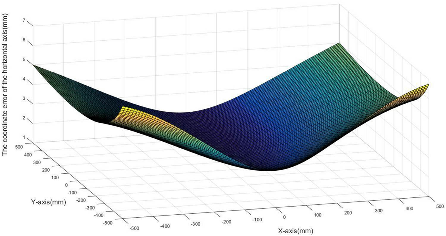
Influence of impact point coordinates on horizontal coordinate errors of the point of impact.

Influence of impact point coordinates on vertical coordinate errors of the point of impact.
As can be seen, the position error is smallest at the origin and increases with the value of the coordinates. The horizontal error increases significantly as the x-coordinate changes, but changes in the y-coordinate can always keep lateral error within 1 mm. Similarly, the vertical error increases significantly as the y-coordinate changes, but changes in the x-coordinate can also keep vertical error within 1 mm. In practical applications, effective detection target surfaces generally have dimensions of ±500 mm × ±500 mm. This can keep position errors within a relatively small range and ensure measurement accuracy.
When the placement distance error of the CCDs in the vertical target screen is 1 mm, the focal length error of the front optical lens is 0.14 mm, and the screen angle error is 0.1°, and the horizontal angle error between the trajectory detection direction and the z-axis is as shown in Figure 4.

Horizontal angle error between the trajectory line and the z-axis.
Horizontal errors within the target plane can be controlled within 0.3°, as shown in Figure 4. Such errors are smaller in regions closer to the x = 0 plane, but increase as the horizontal coordinates of the point of impact take on larger values. However, errors are not symmetrically distributed from left to right on the x = 0 plane. This is because the outward direction of the projectile is random. Projected points
Given the same system parameter values, the vertical angle error between the trajectory line and the z-axis is as shown in Figure 5.

Vertical angle error between the trajectory line and the z-axis.
As shown in Figure 5, vertical angle errors in the target screen generally do not exceed 0.2°, smaller than horizontal angle errors. When y-coordinates are smaller, angle errors can be kept within 0.1°, while x-coordinates have a lesser effect on fluctuations in vertical angle errors. As y-coordinates increase, angle errors tend to increase, while x-coordinates will have a larger impact on vertical angle errors. However, peak error values are in the vicinity of 0.2° and can ensure error precision.
When the same values are set for system parameters, errors in the speed of the projectile similarly vary with changes in the coordinates of the target surface, as shown in Figure 6.

Influence of the point of impact on the speed error of the projectile.
As can be seen, changes in the x-coordinate have a greater impact on errors in the speed of the projectile when the y-coordinate is smaller. The impact of the x-coordinate on errors in the speed of the projectile is relatively stable. Even though the horizontal and vertical coordinates will simultaneously have an impact on errors in projectile speed, combined with the measured projectile direction, we can easily find that the speed and the direction errors in the vicinity of the x = 0 plane and are relatively small. Effective measurement target planes are selected symmetrically with the x = 0 plane as the axis. This selection method not only makes installation easier and reduces the time needed for calibration, but can also effectively reduce measurement errors.
4 Conclusion
Based on intersecting-CCD vertical target screens, this study has designed a triangular composite light-screen target and derived the horizontal and vertical angles of intersection between the trajectory line and the z-axis for such light screens. Through parametric equations, we derived an expression for the speed of the projectile. Through error analysis, we discovered that errors in the horizontal and vertical coordinates with respect to the point of impact are affected by the coordinates of impact, with error values increasing with the two orthogonal coordinates. However, x-coordinates have a more significant impact on the horizontal axis error of the point of impact than y-coordinates. Similarly, y-coordinates have a more significant impact on the vertical axis error of the point of impact than x-coordinates. In an effective receiving target screen, points of impact near the origin are more precise. Greater error compensation is required during initial system calibration for regions further from the origin.
Through a simulation analysis of the horizontal and vertical angle errors between the trajectory line and the z-axis, we find that horizontal angle errors can be kept within 0.3°, whereas vertical angle errors generally do not exceed 0.2°. In addition, horizontal coordinates of the point of impact have a more significant influence on the horizontal angle error. Vertical coordinates have a more significant impact on the vertical angle error. Errors in the speed of the projectile are also affected by the orthogonal coordinates. When y-coordinates are larger, fluctuations in speed error are relatively stable. On the whole, errors in speed and direction are smaller in the vicinity of the x = 0 plane. This provides some convenience for the initial system calibration.
In future work, a further analysis on this system and building of experimental platforms in the field to carry out specific analysis by combining simulation data with experimental results, will be conducted. The system with a sound calibration data compensation to make measurements more precise, will be provided.
-
Funding information: This study is supported by a key laboratory project of Shaanxi provincial department of education (Grant No. 20JS057).
-
Authors contribution: All authors have accepted responsibility for the entire content of this manuscript and approved its submission.
-
Conflict of interest: The authors state no conflict of interest.
References
[1] Wang LF, Wang H, Jiang HZ, Li LQ, Tuo X, Wan XT, et al. Environmental adaptability test and design of carrier-based aviation ammunition. Ordnance Ind Autom. 2019;38(8):46–8.Search in Google Scholar
[2] Ni JP. Technol application Meas Light screen array. Bei Jing: National Defense Industry Press; 2014. p. 4–22.Search in Google Scholar
[3] Madsen LS, Waleed M, Casacio CA, Terrasson A, Stilgoe AB, Taylor MA, et al. Ultrafast viscosity measurement with ballistic optical tweezers. Nat Photonics. 2021;15(1):386–92.10.1038/s41566-021-00798-8Search in Google Scholar
[4] Salzenstein P, Pavlyuchenko E. Uncertainty evaluation on a 10.52 GHz (5 dBm) optoelectronic oscillator phase noise performance. Micromachines. 2021;12(5):474.10.3390/mi12050474Search in Google Scholar PubMed PubMed Central
[5] Kumru F, Akca T, Acar RS. Performance evaluation of nonlinear filters on impact point prediction of ballistic targets. In: 2017 20th International Conference on Information Fusion (Fusion); 2017. p. 1–7.10.23919/ICIF.2017.8009642Search in Google Scholar
[6] Zong-Min YE, No U. Research on implementation method of infrared imaging guided anti-ship missile. Infrared. 2019;15(2):871–9.Search in Google Scholar
[7] Zheng S, Wang Z, Xu L. Research on the application of photoelectric detection information in air defense missile weapon system. Aerosp Control. 2019;24(1):23–31.Search in Google Scholar
[8] Li H, Zhang X, Zhang X, Lu L. Detection sensitivity correction calculation model and application of photoelectric detection target in four-screen intersection testing system. Measurement. 2021;177(3):109281.10.1016/j.measurement.2021.109281Search in Google Scholar
[9] Liu Y, Jiang M, Zhang Z, Li Y. Study on aerodynamic characteristics of projectile in plateau based on shooting test. J Ordnance Equip Eng. 2019;12(8):557–62.Search in Google Scholar
[10] Wu Z, Zhang X. On-sate calibration method of target distance of the sky screen target velocity measuring system. Optik. 2019;178:483–7.10.1016/j.ijleo.2018.09.150Search in Google Scholar
[11] Chen R, Ni JP, Liu J. Uncertainty analysis of coordinate measurement of six-light-screen array sky screen vertical target based on engineering model. Acta Armamentarii. 2019;46(11):1362–75.Search in Google Scholar
[12] Lu CG, Wang YJ, Yao ZJ, Zhang L, Fan B. Attack angle measurement of projectile with multi-linear array photoelectric vertical target. Transducer Microsyst Technol. 2016;31(2):75–84.Search in Google Scholar
[13] Dong T, Ni JP. Measurement principle of six-light-screen vertical target based on sky screen. J Appl Opt. 2011;32(5):913–6.10.5768/JAO202142.0507001Search in Google Scholar
[14] Kalonia RC, Chhachhia DP, Bajpai PP, Singh M, Biswas I, Yadav MS. Multiple laser-based high-speed digital shadowgraphy system for small caliber projectile-target interaction studies. Optical Eng. 2014;53(3):034104.10.1117/1.OE.53.3.034104Search in Google Scholar
[15] Pan D. Technology of anti-interference of sky screen based on CPLD. Comput Digital Eng. 2017;45(04):655–8.Search in Google Scholar
[16] Shi L. Research on the technology of integrated receiving-transmitting laser screens. Xi’an: Xi’an Technological University; 2010.Search in Google Scholar
[17] Zhang YW, Zhang S, Zhang MY, Zhang HZ Intelligent light screen target coordinate measurement system, CN210570247U; 2020.Search in Google Scholar
© 2021 Hai Li et al., published by De Gruyter
This work is licensed under the Creative Commons Attribution 4.0 International License.
Articles in the same Issue
- Regular Articles
- Circular Rydberg states of helium atoms or helium-like ions in a high-frequency laser field
- Closed-form solutions and conservation laws of a generalized Hirota–Satsuma coupled KdV system of fluid mechanics
- W-Chirped optical solitons and modulation instability analysis of Chen–Lee–Liu equation in optical monomode fibres
- The problem of a hydrogen atom in a cavity: Oscillator representation solution versus analytic solution
- An analytical model for the Maxwell radiation field in an axially symmetric galaxy
- Utilization of updated version of heat flux model for the radiative flow of a non-Newtonian material under Joule heating: OHAM application
- Verification of the accommodative responses in viewing an on-axis analog reflection hologram
- Irreversibility as thermodynamic time
- A self-adaptive prescription dose optimization algorithm for radiotherapy
- Algebraic computational methods for solving three nonlinear vital models fractional in mathematical physics
- The diffusion mechanism of the application of intelligent manufacturing in SMEs model based on cellular automata
- Numerical analysis of free convection from a spinning cone with variable wall temperature and pressure work effect using MD-BSQLM
- Numerical simulation of hydrodynamic oscillation of side-by-side double-floating-system with a narrow gap in waves
- Closed-form solutions for the Schrödinger wave equation with non-solvable potentials: A perturbation approach
- Study of dynamic pressure on the packer for deep-water perforation
- Ultrafast dephasing in hydrogen-bonded pyridine–water mixtures
- Crystallization law of karst water in tunnel drainage system based on DBL theory
- Position-dependent finite symmetric mass harmonic like oscillator: Classical and quantum mechanical study
- Application of Fibonacci heap to fast marching method
- An analytical investigation of the mixed convective Casson fluid flow past a yawed cylinder with heat transfer analysis
- Considering the effect of optical attenuation on photon-enhanced thermionic emission converter of the practical structure
- Fractal calculation method of friction parameters: Surface morphology and load of galvanized sheet
- Charge identification of fragments with the emulsion spectrometer of the FOOT experiment
- Quantization of fractional harmonic oscillator using creation and annihilation operators
- Scaling law for velocity of domino toppling motion in curved paths
- Frequency synchronization detection method based on adaptive frequency standard tracking
- Application of common reflection surface (CRS) to velocity variation with azimuth (VVAz) inversion of the relatively narrow azimuth 3D seismic land data
- Study on the adaptability of binary flooding in a certain oil field
- CompVision: An open-source five-compartmental software for biokinetic simulations
- An electrically switchable wideband metamaterial absorber based on graphene at P band
- Effect of annealing temperature on the interface state density of n-ZnO nanorod/p-Si heterojunction diodes
- A facile fabrication of superhydrophobic and superoleophilic adsorption material 5A zeolite for oil–water separation with potential use in floating oil
- Shannon entropy for Feinberg–Horodecki equation and thermal properties of improved Wei potential model
- Hopf bifurcation analysis for liquid-filled Gyrostat chaotic system and design of a novel technique to control slosh in spacecrafts
- Optical properties of two-dimensional two-electron quantum dot in parabolic confinement
- Optical solitons via the collective variable method for the classical and perturbed Chen–Lee–Liu equations
- Stratified heat transfer of magneto-tangent hyperbolic bio-nanofluid flow with gyrotactic microorganisms: Keller-Box solution technique
- Analysis of the structure and properties of triangular composite light-screen targets
- Magnetic charged particles of optical spherical antiferromagnetic model with fractional system
- Study on acoustic radiation response characteristics of sound barriers
- The tribological properties of single-layer hybrid PTFE/Nomex fabric/phenolic resin composites underwater
- Research on maintenance spare parts requirement prediction based on LSTM recurrent neural network
- Quantum computing simulation of the hydrogen molecular ground-state energies with limited resources
- A DFT study on the molecular properties of synthetic ester under the electric field
- Construction of abundant novel analytical solutions of the space–time fractional nonlinear generalized equal width model via Riemann–Liouville derivative with application of mathematical methods
- Some common and dynamic properties of logarithmic Pareto distribution with applications
- Soliton structures in optical fiber communications with Kundu–Mukherjee–Naskar model
- Fractional modeling of COVID-19 epidemic model with harmonic mean type incidence rate
- Liquid metal-based metamaterial with high-temperature sensitivity: Design and computational study
- Biosynthesis and characterization of Saudi propolis-mediated silver nanoparticles and their biological properties
- New trigonometric B-spline approximation for numerical investigation of the regularized long-wave equation
- Modal characteristics of harmonic gear transmission flexspline based on orthogonal design method
- Revisiting the Reynolds-averaged Navier–Stokes equations
- Time-periodic pulse electroosmotic flow of Jeffreys fluids through a microannulus
- Exact wave solutions of the nonlinear Rosenau equation using an analytical method
- Computational examination of Jeffrey nanofluid through a stretchable surface employing Tiwari and Das model
- Numerical analysis of a single-mode microring resonator on a YAG-on-insulator
- Review Articles
- Double-layer coating using MHD flow of third-grade fluid with Hall current and heat source/sink
- Analysis of aeromagnetic filtering techniques in locating the primary target in sedimentary terrain: A review
- Rapid Communications
- Nonlinear fitting of multi-compartmental data using Hooke and Jeeves direct search method
- Effect of buried depth on thermal performance of a vertical U-tube underground heat exchanger
- Knocking characteristics of a high pressure direct injection natural gas engine operating in stratified combustion mode
- What dominates heat transfer performance of a double-pipe heat exchanger
- Special Issue on Future challenges of advanced computational modeling on nonlinear physical phenomena - Part II
- Lump, lump-one stripe, multiwave and breather solutions for the Hunter–Saxton equation
- New quantum integral inequalities for some new classes of generalized ψ-convex functions and their scope in physical systems
- Computational fluid dynamic simulations and heat transfer characteristic comparisons of various arc-baffled channels
- Gaussian radial basis functions method for linear and nonlinear convection–diffusion models in physical phenomena
- Investigation of interactional phenomena and multi wave solutions of the quantum hydrodynamic Zakharov–Kuznetsov model
- On the optical solutions to nonlinear Schrödinger equation with second-order spatiotemporal dispersion
- Analysis of couple stress fluid flow with variable viscosity using two homotopy-based methods
- Quantum estimates in two variable forms for Simpson-type inequalities considering generalized Ψ-convex functions with applications
- Series solution to fractional contact problem using Caputo’s derivative
- Solitary wave solutions of the ionic currents along microtubule dynamical equations via analytical mathematical method
- Thermo-viscoelastic orthotropic constraint cylindrical cavity with variable thermal properties heated by laser pulse via the MGT thermoelasticity model
- Theoretical and experimental clues to a flux of Doppler transformation energies during processes with energy conservation
- On solitons: Propagation of shallow water waves for the fifth-order KdV hierarchy integrable equation
- Special Issue on Transport phenomena and thermal analysis in micro/nano-scale structure surfaces - Part II
- Numerical study on heat transfer and flow characteristics of nanofluids in a circular tube with trapezoid ribs
- Experimental and numerical study of heat transfer and flow characteristics with different placement of the multi-deck display cabinet in supermarket
- Thermal-hydraulic performance prediction of two new heat exchangers using RBF based on different DOE
- Diesel engine waste heat recovery system comprehensive optimization based on system and heat exchanger simulation
- Load forecasting of refrigerated display cabinet based on CEEMD–IPSO–LSTM combined model
- Investigation on subcooled flow boiling heat transfer characteristics in ICE-like conditions
- Research on materials of solar selective absorption coating based on the first principle
- Experimental study on enhancement characteristics of steam/nitrogen condensation inside horizontal multi-start helical channels
- Special Issue on Novel Numerical and Analytical Techniques for Fractional Nonlinear Schrodinger Type - Part I
- Numerical exploration of thin film flow of MHD pseudo-plastic fluid in fractional space: Utilization of fractional calculus approach
- A Haar wavelet-based scheme for finding the control parameter in nonlinear inverse heat conduction equation
- Stable novel and accurate solitary wave solutions of an integrable equation: Qiao model
- Novel soliton solutions to the Atangana–Baleanu fractional system of equations for the ISALWs
- On the oscillation of nonlinear delay differential equations and their applications
- Abundant stable novel solutions of fractional-order epidemic model along with saturated treatment and disease transmission
- Fully Legendre spectral collocation technique for stochastic heat equations
- Special Issue on 5th International Conference on Mechanics, Mathematics and Applied Physics (2021)
- Residual service life of erbium-modified AM50 magnesium alloy under corrosion and stress environment
- Special Issue on Advanced Topics on the Modelling and Assessment of Complicated Physical Phenomena - Part I
- Diverse wave propagation in shallow water waves with the Kadomtsev–Petviashvili–Benjamin–Bona–Mahony and Benney–Luke integrable models
- Intensification of thermal stratification on dissipative chemically heating fluid with cross-diffusion and magnetic field over a wedge