
Fuzzy induced controller for optimal power quality improvement with PVA connected UPQC
-
Ravada Simhachalam
 und
Agam Das Goswami
und
Agam Das Goswami


Abstract
The major power quality issues in grid are voltage fluctuations and harmonics. For better power quality of the power system during disturbances on the grid, the UPQC device is utilized to maintain voltage magnitude and reduced harmonics. At the DC link of UPQC along with the capacitor, a renewable PV source is connected which contributes in voltage compensation by the series VSC and harmonics compensation by the shunt VSC. For stable DC voltage generation from PV source a modified P&O MPPT with DC reference is included controlling the boost converter connected to PV source. The controllers of VSCs are operated by feedback loop synchronized schematics with voltage reference generation in series VSC control and current reference generation in shunt VSC control. The shunt control is updated with hybrid Fuzzy-PI controller replacing the traditional PI controller further improving the power quality of the grid. The hybrid Fuzzy-PI varies the K p and K i gains as per the error generated by the DC voltage comparison concerning 25 rule-base for each gain. A comparative performance analysis is done with both the controllers in the shunt converter and the results are generated using MATLAB Simulink software.
1 Introduction
There are many issues in power systems which includes voltage sags and voltage swells caused by sudden load changes on the grid (Ahmed et al. 2022). Along with grid voltage fluctuations, current harmonics generation introduced when operating non-linear loads is one of the major issues (Madhaiyan and Subramaniam 2015). These harmonics generated by the non-linear load may damage other loads and even the main source as they are connected in parallel to the non-linear load. To mitigate the voltage fluctuations series compensation devices like Dynamic Voltage Restorer (DVR) or Static Synchronous Series Compensator (SSSC) and for harmonics compensation, Active power filter (APF) or Static Synchronous Compensator (STATCOM) is used (Mansor et al. 2020; Sarita et al. 2020). In order to achieve both voltage fluctuation compensation and harmonic mitigation hybrid device like UPQC need to be connected to the grid with back-to-back connected VSCs (Kabra and Donepudi 2022; Ray et al. 2022). At the common DC link of the back-to-back VSCs, a parallel capacitor is connected along with the PV source.
Along with voltage fluctuation compensation and harmonics mitigation, the PV source injects active power into the grid through series VSC and reactive power through shunt VSC (Patnaik and Panda 2017). The series VSC is controlled using a voltage reference generation controller and the shunt VSC is controlled using a current reference generation controller (Malekpour et al. 2018). These controllers take feedback from the Point of Common Coupling (PCC) voltages and source currents to generate synchronized pulses for both the VSC modules. The test system with PV source integrated UPQC compensates for the voltage fluctuations and source current harmonics. The VSC connected in the UPQC module comprises six switches connected in a 3-legged format creating three-phase AC terminals on one side and DC terminals on the other side. One VSC is connected in shunt to the test system on the load.
The load side and the other VSC is connected in series to the transmission line on the source side through three individual series transformers. The shunt VSC is operated with current as the reference component and the series VSC is operated with voltage as the reference component. The series VSC module acts as a voltage compensation device that injects or absorbs the voltage as per sag or swell created in the transmission line due to fault. The shunt module compensates for the current harmonics generated by the non-linear load mitigating the injection of these harmonics into the source side. DC-link link capacitor is the element used for support of UPQC which is an inter-link between the series and shunt VSC.
In a conventional UPQC system, the DC link is only connected with a capacitor which has restrictions to compensate for certain voltage levels and reactive power. The rating of the capacitor decides the compensation capability of UPQC to the faults in the grid (Rauf and Khadkikar 2015; Samal et al. 2020). The module has no capability to inject active power as there will be no source that generates active power. The controllers of conventional UPQC are very simple with feedback taken from source voltages, current, and DC link voltage. Simple voltage control of the series module and current control of the shunt module is done with a reduction of harmonics and voltage fluctuations (Venkatachalam and Saravanan 2020). However, in modern technology, the DC link capacitor is updated with renewable sources like PVA for the injection of active power into the grid along with reactive power from the shunt module (Taherian et al. 2020). Along with the PV source, any other DC source like a battery or fuel cell can also be connected for more active power injection capability (Yahiya and Uzair 2016).
For a better response to the controllers, the DC voltage regulator is updated with the MPPT algorithm for maximum power extraction the from PV source (Meng et al. 2022). Along with this modification, the PI controller can be replaced by different complex controllers like sliding mode or ANFIS controllers (Chennai and Benchouia 2014). This improves the response of the control module making the UPQC operate at improved performance. The system will be more stable to the faults caused in the grid and the voltage will be stabilized at a faster response rate.
In the Figure 1. Three phase source with phase voltages V Mabc is connected to three phase non-linear load which is RL branch connected to diode bridge rectifier. This non-linear load introduced injects harmonics in the grid which is one of the power quality issues which needs to be mitigated. The voltage fluctuations are introduced by the supply source causing sags and swells in the voltage magnitude (Malekpour et al. 2018). The PV source integrated UPQC is connected at the inter section of source and load, so as to mitigate harmonics and voltage fluctuations introduced in the grid (Yao et al. 2016). The series VSC is connected in series to the line through three individual transformers and the shunt VSC is connected directly to the grid in parallel (Samanta and Chanda 2021; Yao et al. 2016). Both modules are connected with series inductors for current harmonics mitigation generated by the VSCs. These VSCs are controlled with feedback loop control schematics integrated with PI and Hybrid Fuzzy-PI controllers.
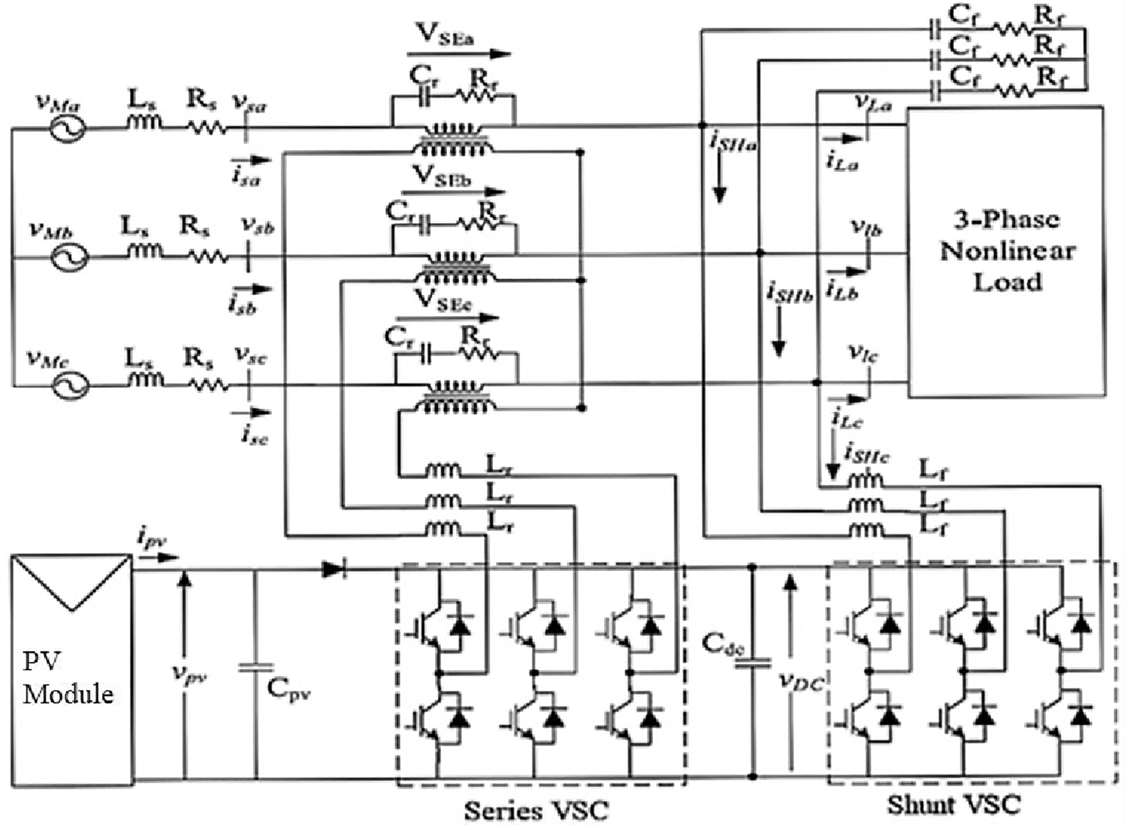
PV source integrated UPQC test system.
This paper introduces a PV source with boost converter controlled by modified P&O MPPT connected to UPQC in Section 1. The configuration of the PV source UPQC module in Section 2, the control system modification with hybrid Fuzzy-PI controller is discussed in Section 3, and the comparative simulation analysis results are presented in Section 4. The paper’s conclusion is given in Section 5, which defines the system improvements and results in discussion, followed by references used in this paper.
2 PV source UPQC configuration
The PV is a solar irradiation dependent source which is unstable as per the variable irradiation in a day. The voltage output of the PV module may impact the performance of UPQC and induce voltage instability into the grid. Hence the PV source voltage need to be stabilized even during variable irradiation conditions using a boost converter. The boost converter is controlled by modified P&O MPPT control which is included with a DC voltage reference. The circuit structure of PV module connected at DC link of UPQC can be seen in Figure 2.
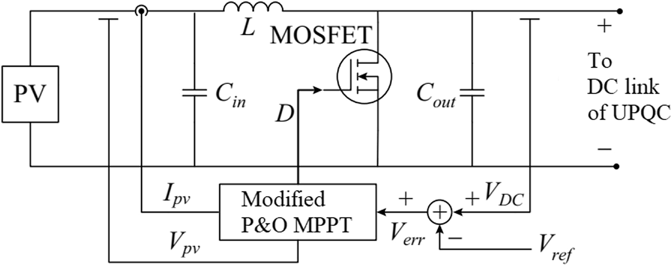
PV module internal circuit.
The modified P&O MPPT takes feedback of V err along with V pv and I pv for DC link voltage stabilization. The duty cycle (D) of MOSFET in the boost converter is controlled with respect to the considered parameters of the PV and reference voltage (V ref). The internal structure of modified P&O MPPT algorithm can be seen in Figure 3.
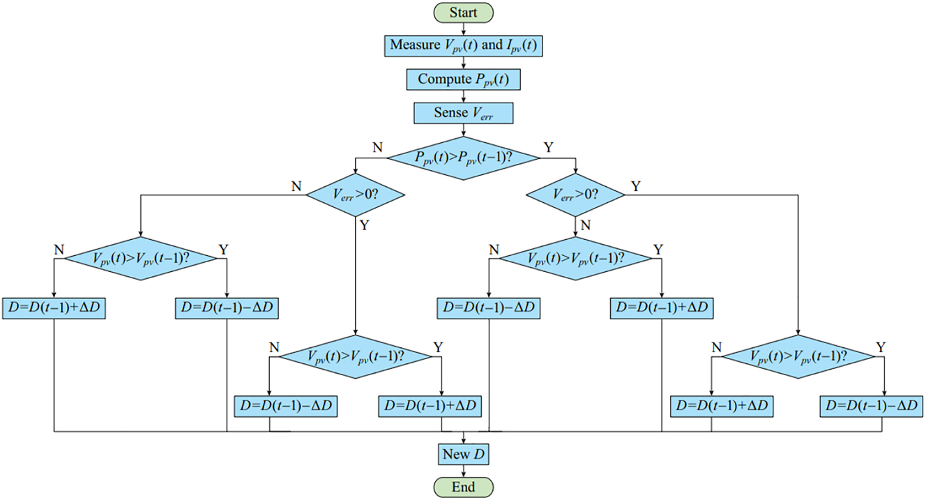
Modified P&O MPPT algorithm.
The new updated D is varied as per the V err generated by the comparison of measured DC link voltage V dc and reference voltage V ref. The change in D is given as per the below given conditions.
Here, P pv(t) and V pv(t) are present values of PV power and voltage, P pv(t − 1) and V pv(t − 1) are previous values of PV power and voltage. As per the given conditions in the algorithm, the previous duty cycle D(t − 1) is either incremented or decremented with ∆D. The ∆D value can be updated as per the response of the controller and tuned as per the DC voltage stabilization. For the PV module to operate at specified DC link voltage for the UPQC the reference values calculated as given below.
Here, V L is the line voltage of the three-phase supply source and ‘m’ is the modulation index considered as 1.
For DC link capacitance C dc value the expression is given as
Here, K is energy variation dynamic factor taken as 0.1, A is overloading factor taken as 1.5, V p is phase voltage of the source, I sh is the phase shunt compensation current of shunt VSC, ‘t’ required steady state time (Meng et al. 2022), V dc is DC bus voltage, V dc1 possible lower DC voltage.
The shunt ripple filter inductor L f expression is given as
Here, f sh is shunt converter switching frequency, ∆I is the ripple current of shunt connected inductor taken as 20% of grid current.
The series ripple filter inductor in (Simões et al. 2016), L se expression is given as
Here, K se is the turn’s ratio of the series transformer taken as 3, and ∆I se is the ripple current of series connected inductor taken as 20% (Malekpour et al. 2018) grid current, f se is the series VSC switching frequency.
The configuration of the system is done as per the values given by the above expressions and the modeling is done with control modules modeled as in Section 3.
3 Controller modeling
The control structures for operating VSC modules of the PV source UPQC are slightly modified from the conventional UPQC control structures (Jayakumar and Alexander Stonier 2020; Meng et al. 2022). Both the controllers take feedback from grid system voltage and current measurement so as to make the VSC modules to operate in synchronization to the grid (Lu et al. 2016). The series VSC control structure only consider voltage measurements as it is a voltage compensation module (Malekpour et al. 2018). However, the shunt VSC control structure includes voltage measurement and also current measurement as the shunt module needs to compensate current harmonics (Saggu et al. 2018). The shunt VSC also need to be operated in synchronization to the grid voltage (Devassy and Singh 2018).
3.1 Series VSC control structure
The series VSC control is an in phase compensation and pre sag compensation strategy. The series VSC needs to inject or absorb voltage from the grid as per the sag and swell created respectively (Patjoshi et al. 2017). So for this the controller has to be operated in synchronization to the grid (Prajapati and Prasad 2020). Therefore, the controller needs feedback from the source voltage with PLL (Yao et al. 2016) (Phase Locked Loop) module used to determine the phase and frequency of the main source supply (Devassy and Singh 2018; Poongothai and Srinath 2020). The complete schematic of series VSC controller is shown in Figure 4.
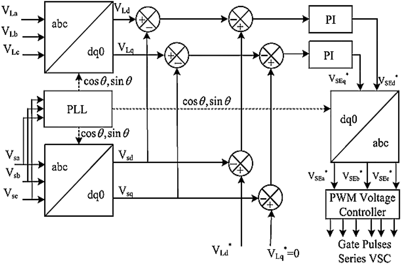
Series VSC control structure.
As seen in Figure 2 the controller takes feedback from source phase voltages V Sabc and load phase voltages V Labc . The source voltages are considered for PLL so as to determine the phase angle θ at which the grid voltages are operating (Abdoli et al. 2018). The PLL module is used to calculate the stationary reference frame d–q–0 components of both source voltages and load voltages using Park’s transformation equation given as
From the above expression the dq components of the source voltages V Sd V Sq and load voltages V Ld V Lq are considered which are compared to each other (Da Silva et al. 2020). The comparison expressions are given as
Here, V Ed V Eq are the error d–q components generated after comparison. Now the reference error component is generated by below expressions.
Here,
Now for the final reference voltage components the expression is given as
These final reference values generated by the comparison of error components are fed to individual PI controller to generated reference signals (Boukhechem et al. 2020).
Form these final reference signals
As per the reference sinusoidal signals the pulses to the inverter are generated by SPWM technique controlling the inverter output voltage (Patjoshi et al. 2017). With respect to this the voltage at the load side is compensated and tends to maintain at given reference values are per the user (Zahariah and Pon Symon 2021).
3.2 Shunt VSC control structure
To control the shunt VSC the shunt controller takes feedback from source voltages V Sabc , Load currents I Labc , PV source voltage and current V pv I pv and DC link voltage V dc (Dash and Ray 2018). The load current d–q axis components I Ld I Lq are generated by using the expression as in (7). For loss current component I loss generation a PI controller fed DC voltage comparison is considered where the reference DC voltage is generated using MPPT algorithm (Sangwongwanich and Blaabjerg 2019).
A P&O MPPT algorithm is adopted in the controller which takes feedback of PV source voltage and current (
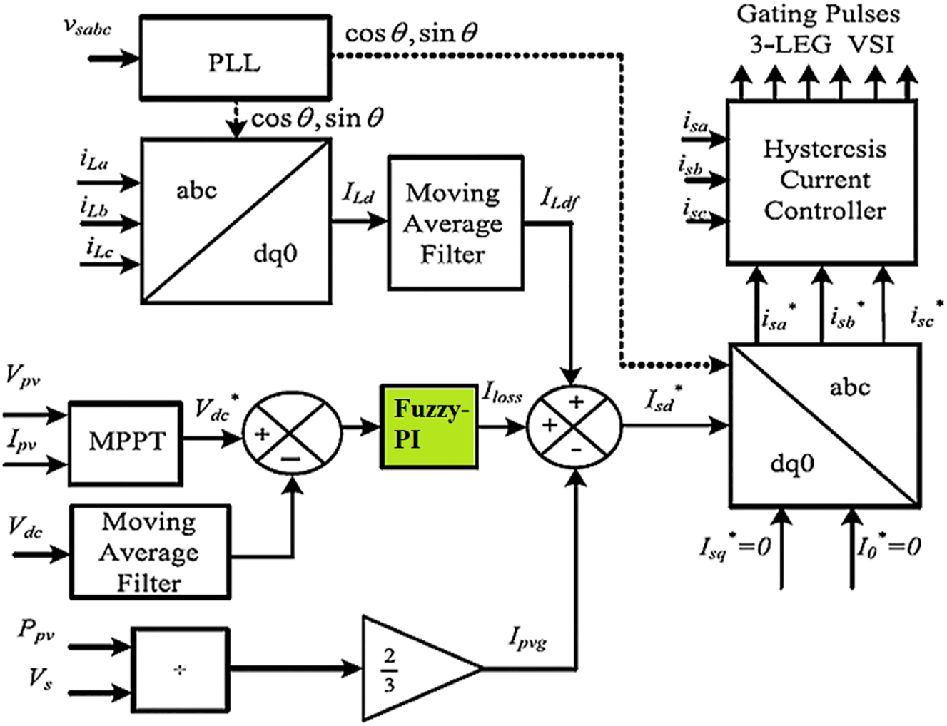
Shunt VSC control.
Here, the reference DC voltage
Here, P
pv is the power generated by PV source taken as
Here, I
Ldf
is the filtered load current d-axis component with reduced disturbances. For conversion of d–q–0 to abc reference signals the expression (16) is considered where
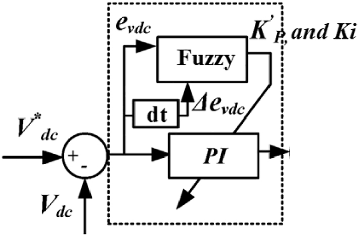
3.3 Fuzzy-PI control module
In the above shunt VSC control the PI controller used for calculation of loss current component I loss is a conventional controller (Campanhol et al. 2019). This controller has high disturbances and oscillations because of the preciseness of the controller with respect to K p and K i gains. This leads to disturbed current reference signal generation because of which the shunt VSC does not mitigate the harmonics optimally. To overcome this drawback the PI controller in Dimitroulis and Alamaniotis (2021), is replaced with Fuzzy-PI (Song et al. 2020; Saha and Biswas 2021). Which generates varible K p and K i values as per the error generated improving the performance of the controller. With reduced disturbances in the reference signal the shunt VSC mitigates the harmonics more optimally reducing further impact on the grid.
The Fuzzy-PI module is modeled with two input components error (e) and difference in error (de), one output component K p or K i (Campanhol et al. 2019; Vigneysh and Kumarappan 2017; Yap et al. 2021). Each input component is included with five membership functions type taken as triangular (Dimitroulis and Alamaniotis 2021; Song et al. 2020). The membership functions for the same Fuzzy-PI design is shown in Figures 6 and 7.
Fuzzy-PI controller.
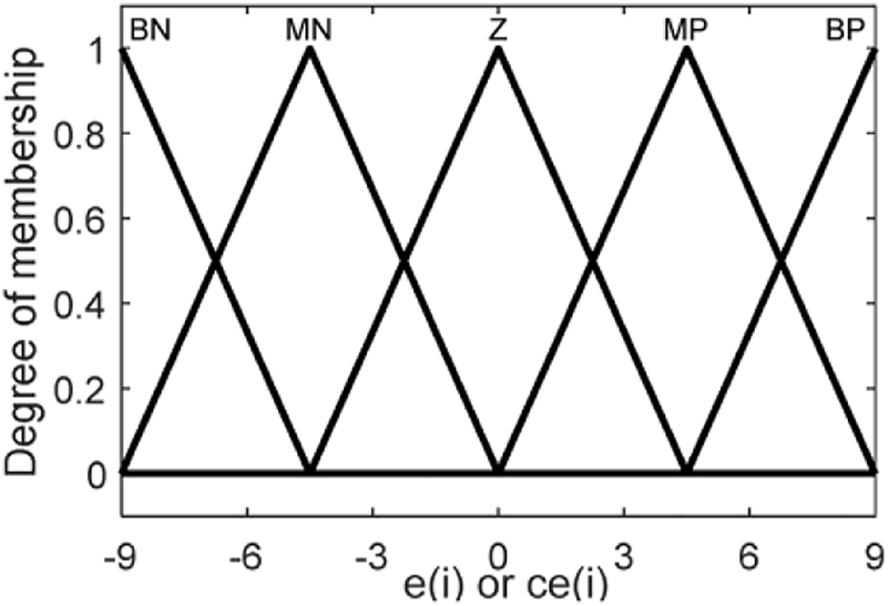
FIS membership functions of components ‘e’ ‘ce’ and ‘K p or K i ’.
Here component ‘e’ is generated by comparison of reference DC voltage
The membership functions are represented as Big Negative (BN), Medium Negative (MN), Zero (Z), Medium Positive (MP), Big Positive (BP) (Arcos-Aviles et al. 2018). To generate the output from the controller a 25 rule base is taken with IF-AND-IF-THEN rule structure (de Carne et al. 2019). A 5 × 5 rule base is taken for better resolution and to generate stable results with more accuracy. Lesser number of membership functions lead to reduced accuracy and response time of the controller. The rule base for the given Fuzzy module is given in Table 1.
Rule base for K p or K i .
| Kp | Ki | ||||||||||
|---|---|---|---|---|---|---|---|---|---|---|---|
| ce | e | ce | e | ||||||||
| BBN | MMN | ZZ | MMP | BBP | BBN | MMN | ZZ | MMP | BBP | ||
| BN | BB | BB | SS | BB | BB | BBN | BB | MM | SS | MM | BB |
| MN | BB | BB | SS | BB | BB | MMN | BB | MM | MM | MM | BB |
| ZZ | BB | MM | MM | MM | BB | ZZ | BB | BB | MM | BB | BB |
| MMP | BB | BB | SS | BB | BB | MMP | BB | MM | MM | MM | BB |
| BBP | BB | BB | SS | SS | BB | BBP | BB | MM | SS | MM | BB |
With the above updated of the current loss component a comparative analysis is carried out with conventional PI controller generation results using simulation modeling in next section.
4 Simulation results comparative analysis
With all the above modules of the test system which include three phase main source feeding non-linear load connected with PV-UPQC device at the intersection, modeling is done in MATLAB Simulink environment. The below table parameters are used for the modeling of the given system (Table 2).
System parameters.
| Name of the module | Parameters |
|---|---|
| Grid | V ph-ph, rms = 415 V, R s = 0.5 Ω, L s = 1 mH. |
| Loads | Balanced non-linear load 1 R
1 = 25 Ω. Unbalanced (A–C) non-linear load R 2 = 25 Ω. |
| UPQC |
C
dc
= 9 mF, shunt inductance L
f
= 3 mH, series inductance L
r
= 3.6 mH. Series T/F = 10 kVA, 50 Hz, n = 3:1, series control regulator gains K
pse
, K
ise
= 8, 1200. Shunt control regulator gains K psh K ish = 1.5, 0.1. Switching frequency f s = 10 kHz |
| PV | Series cells N s = 1628, parallel cells N p = 5000, reference temperature T c = 30 °C, reference solar irradiation S c = 1000 W/mt2, V c = 0.43 V, I c = 10 mA. |
The controllers are modeled as per the given structures in section III and the simulations are run for 1 s with different operating conditions. As per the given case in the total simulation time of 1.2 s voltage sags are created from 0.4 to 0.6 s and voltage swells are created from 0.8 to 1 s. However the harmonics are continuously generated as the non-linear load is connected to the source throughout the simulation time. The resultant graphs generated with respect to above conditions are shown Figure 8.
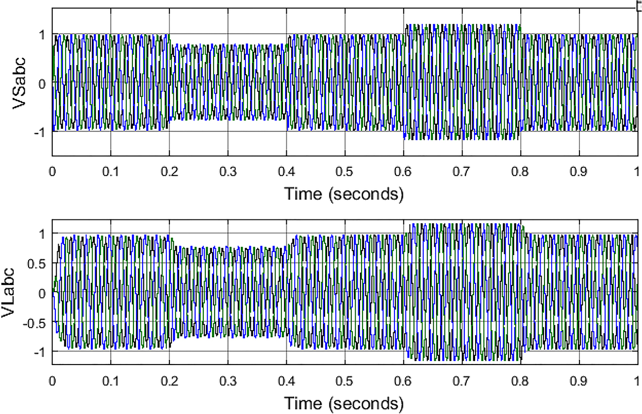
Source and load voltages without PV-UPQC.
In the above Figure 8. Graph the voltage sag and swell created by the source are impacting the load side voltages also creating sag and swell in the load also as there is no PV-UPQC device connected. For same the three phase source current graph with huge harmonics generation due to non-linear load power feeding is shown below in Figure 9.
Source currents without PV-UPQC.
The THD of the above source current graph is shown in Figure 10. With very high value of 28% which is very much greater than the IEEE standard of 5%.
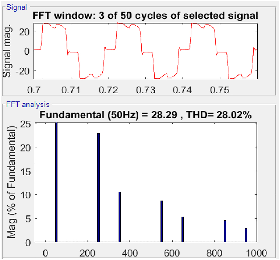
THD of source current without PV-UPQC.
A comparative graph of source voltage and load voltage magnitude is shown in Figure 11. Without any changes representing sag and swell impact on the load.
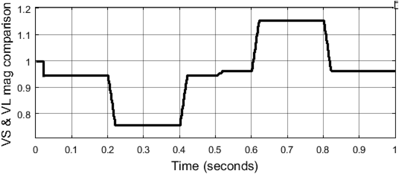
Source and load voltage magnitude comparison without PV-UPQC.
Now, the test system is updated with PV-UPQC at the intersection with and the simulation is run for same sag and swell timing with same simulation time. The PV module is operated with variable irradiation conditions which changes with respect to time. The irradiation, voltage, current and power of PV source can be seen in Figure 12.
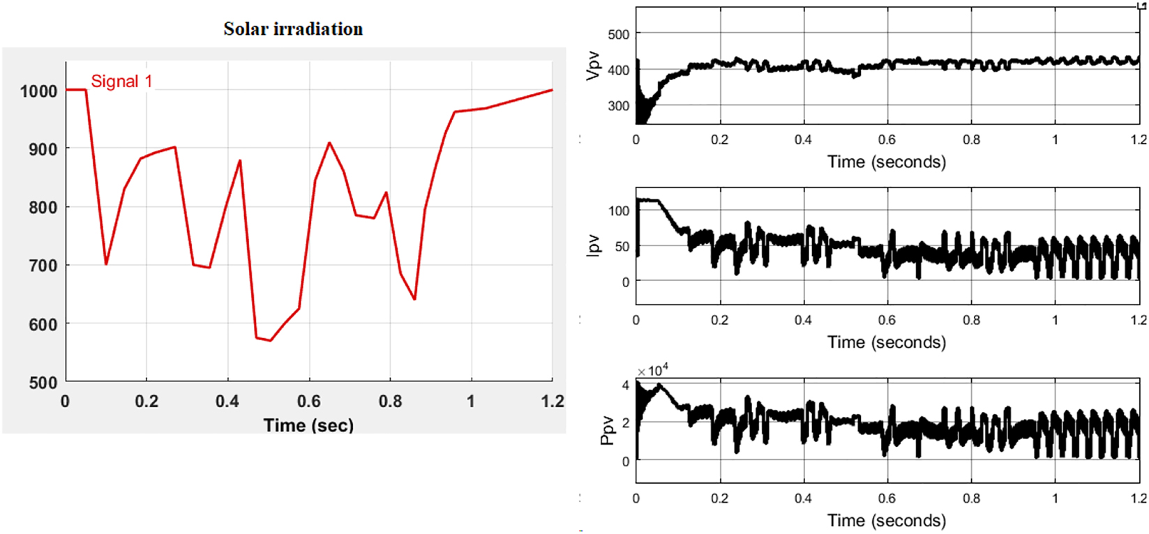
Solar irradiation, voltage, current and power of PV source.
Even with the given variable solar irradiation the voltage output of the boost converter controlled by modified P&O MPPT technique is maintained at 700 V. The output voltage of the converter can be observed in Figure 13.
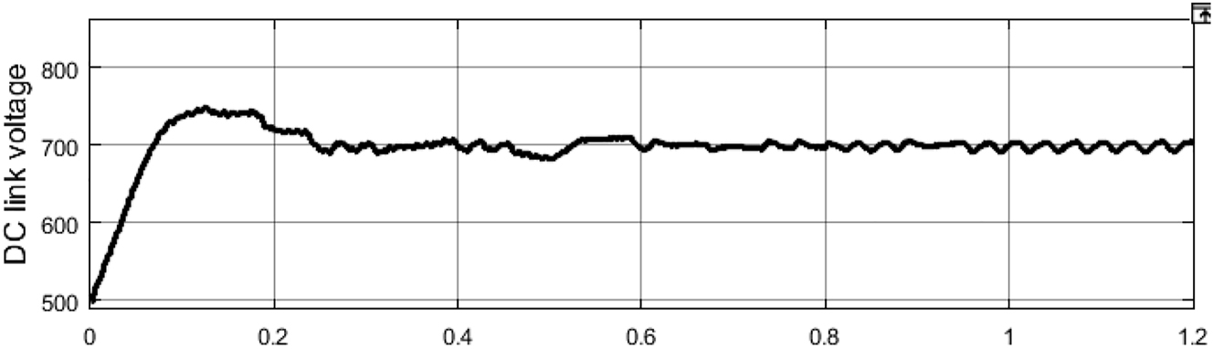
Voltage at the DC link or output of boost converter.
Due to stable voltage magnitude generation at the DC link, load voltage and current harmonics compensation is achieved by UPQC. The below Figure 14 is the source and load 3-ph voltage comparison.
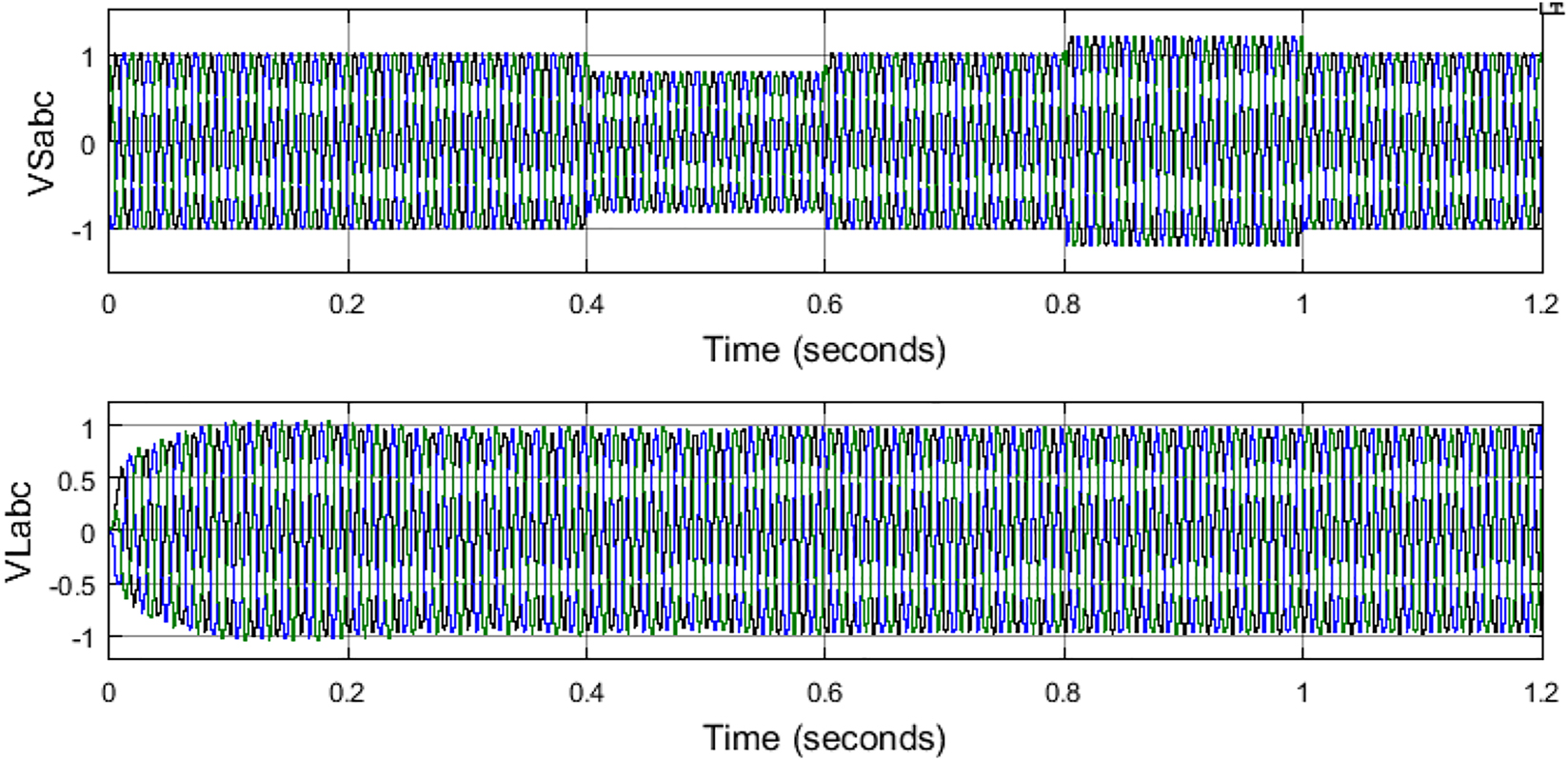
Source and load voltages with PV-UPQC.
As it can be observed that the load voltages are intact and are maintained at 1 pu even with sag and swell created on the source side. This is achieved by the injection and absorption of voltages by the series VSC connected through series transformers on the source side. The compensation voltages from the series VSC as per the sag and swell conditions are shown in Figure 15.
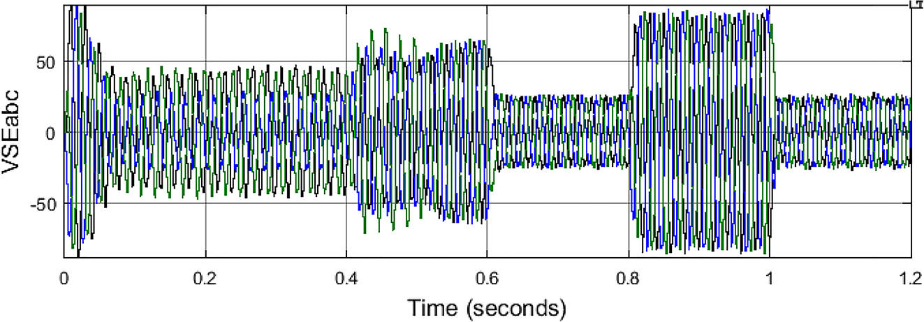
Series VSC compensation voltages.
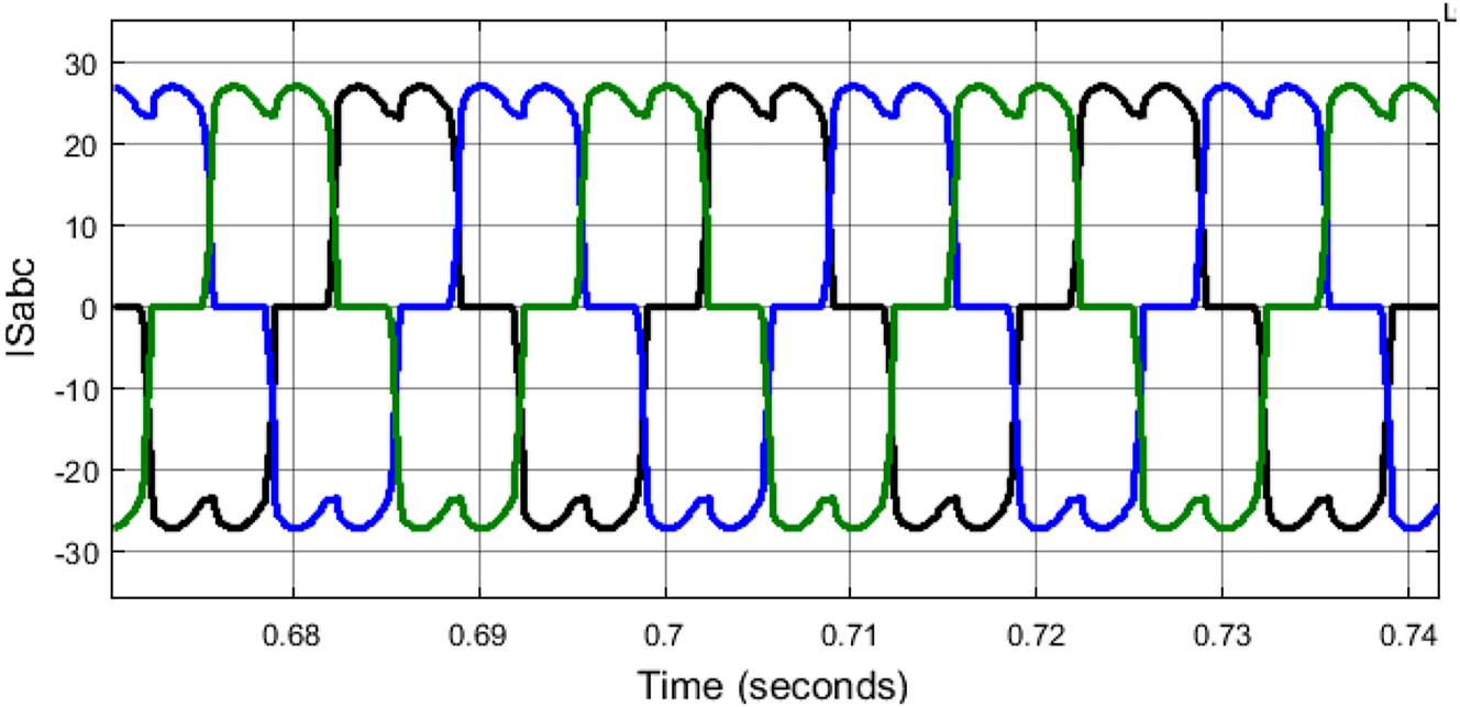
For harmonics generated by the non-linear load after the PV-UPQC shunt VSC connected at the load side the source currents recorded are shown in Figure 16.
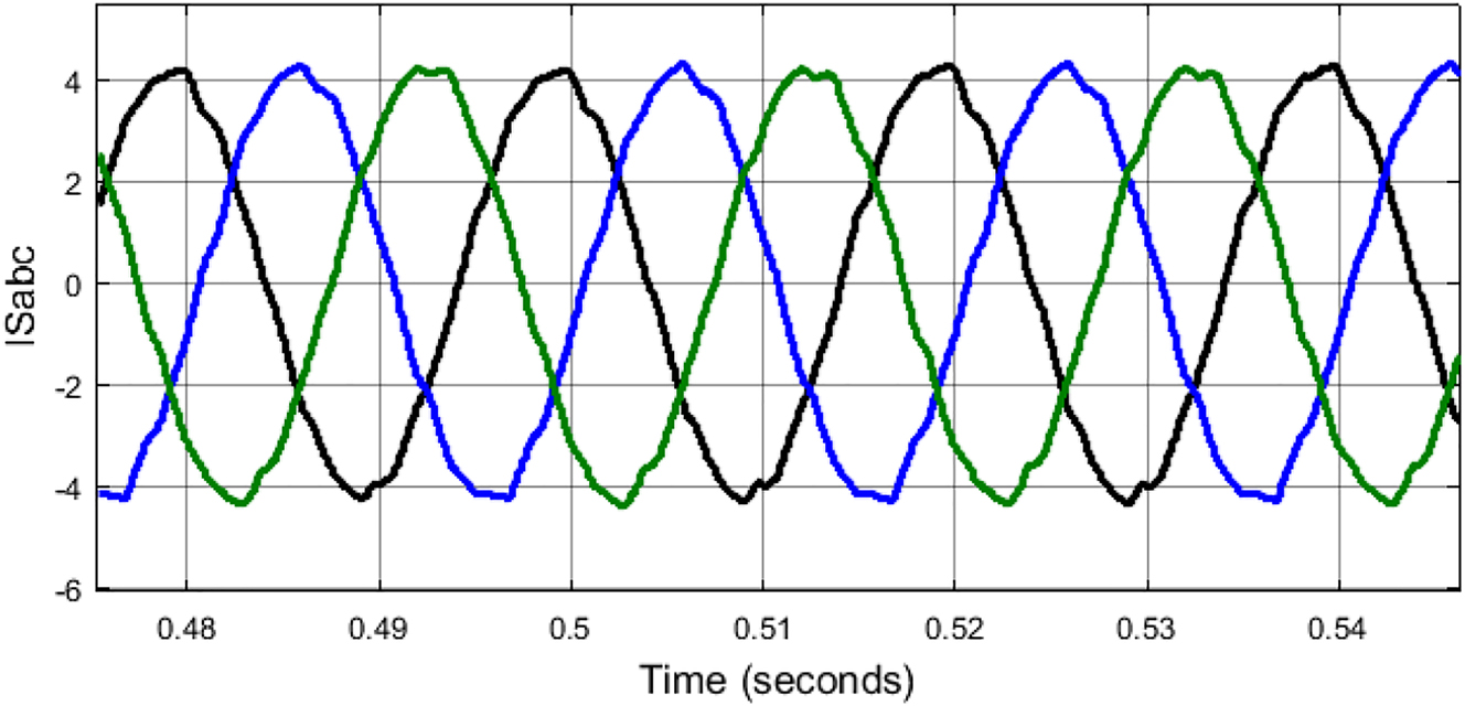
Source currents with PV-UPQC.
As observed the harmonics are mitigated generating nearly sinusoidal waveforms from the source current as the shunt VSC is compensating the non-linear load current harmonics. The compensation shunt VSC current can be seen in Figure 17.
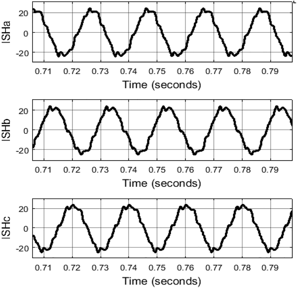
Shunt VSC compensation currents.
The voltage magnitude comparison of source and load voltages can be seen in Figure 18. With load voltage magnitude maintained between 0.95 and 1 pu even during sag and swell conditions created by the source.
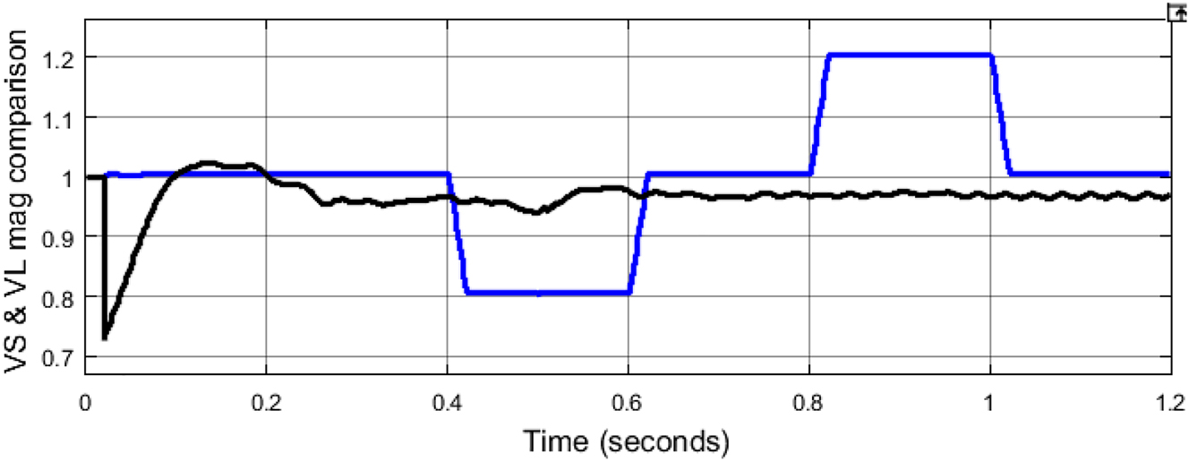
Source and load voltage magnitude comparison with PV-UPQC.
The shunt VSC controller is updated with Fuzzy-PI controller replacing PI controller for further reduction in harmonics and stabilizing the system with better load voltage magnitude. Figure 19 is the rule viewer of the Fuzzy-PI controller K p and K i gains for the given error and difference in error values.
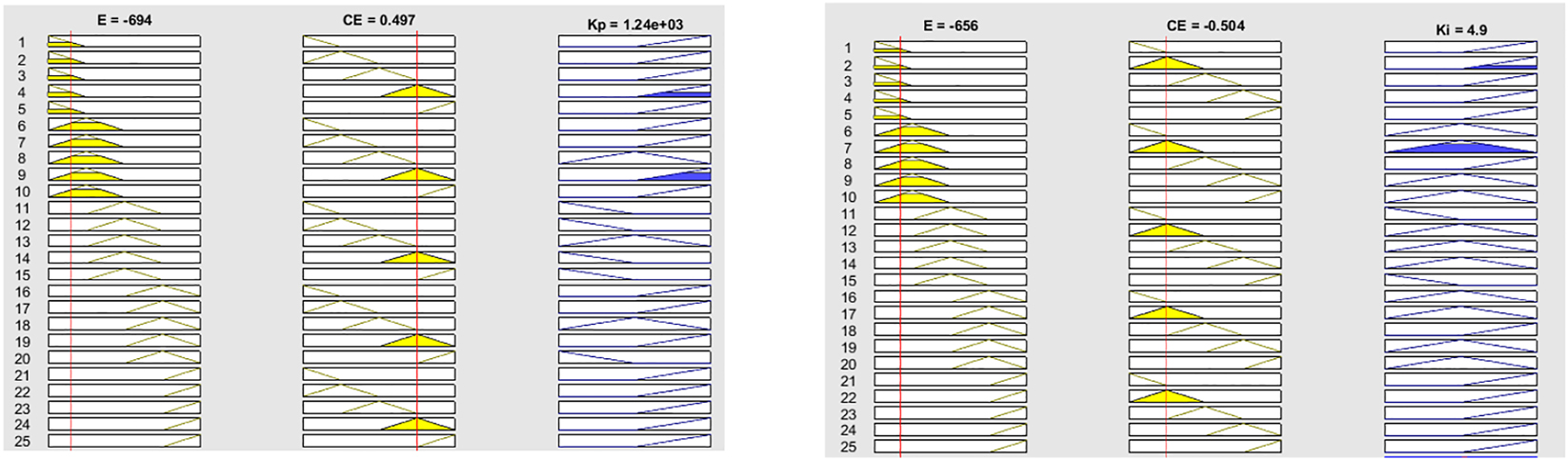
FIS rule viewer of K p and K i gains.
The voltage magnitude of the load voltage is improved with reduced disturbances when the PV-UPQC is operated with Fuzzy-PI controller (Yu and Khan 2022). Therefore, the PV-UPQC has better performance when operated with Fuzzy-PI controller as illustrated Figure 20.
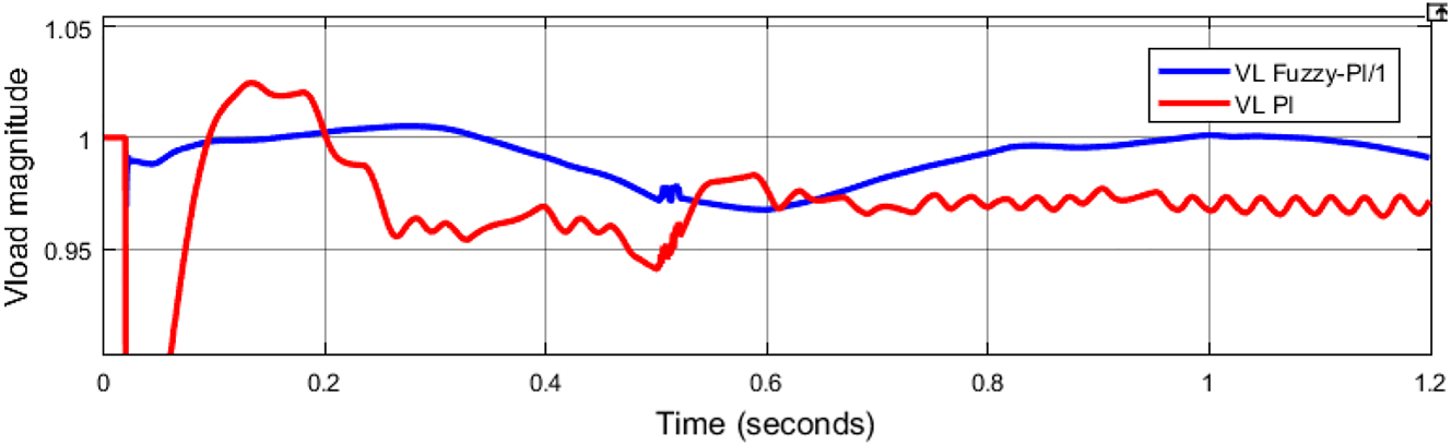
Load voltage magnitude comparison with PI and Fuzzy-PI controllers.
Along with voltage magnitude improvement, the THD of the source current is also reduced to a lower value when the PV-UPQC is operated with the Fuzzy-PI controller. The FFT analysis comparison of source current with PI and Fuzzy-PI controller determining the THD is shown in Figure 21.
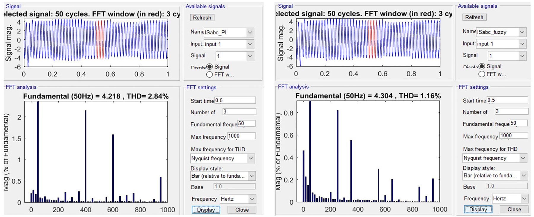
THD comparison of source currents using FFT analysis tool.
A parametric comparative analysis table without and with PV-UPQC integrated with PI and Fuzzy-PI controllers is given in Table 3.
Comparison table.
| Name of the parameter | Voltage sag | Voltage swell | ||||
|---|---|---|---|---|---|---|
| Without PV-UPQC | With PV-UPQC (PI) | With PV-UPQC (Fuzzy-PI) | Without PV-UPQC | With PV-UPQC (PI) | With PV-UPQC (Fuzzy-PI) | |
| Vs mag | 0.8 pu | 0.8 pu | 0.8 pu | 1.2 pu | 1.2 pu | 1.2 pu |
| VL mag | 0.8 pu | 0.97 pu | 0.99 pu | 1.2 pu | 0.97 pu | 1 pu |
| VL ripple | 0.1% | 4.08% | 2.02% | 0.1% | 1% | 0.5% |
| Is THD | 28.02% | 2.84% | 1.16% | 28.02% | 2.84% | 1.16% |
5 Conclusions
In this paper the complete modeling of the test system with PV source integrated UPQC is modeled impacting the system when introduced with different power quality issues. The stabilization of voltage magnitudes is shown when the supply source is introducing sag and swells condition in the system along with improvement in THD of the source current. A comparative analysis is discussed with simulation results shown when the system is operated without and with PV-UPQC device connected at the intersection. Further improvement in load voltage magnitude is achieved and also further mitigation of THD of source current is also shown when the PV-UPQC is operated with Fuzzy-PI controller. The voltage magnitude is stabilized at 1 pu and the THD of the source current is maintained as low as 1.16% with the updated control structure.
-
Author contributions: All the authors have accepted responsibility for the entire content of this submitted manuscript and approved submission.
-
Research funding: None declared.
-
Conflict of interest statement: The authors declare no conflicts of interest regarding this article.
References
Ahmed, M. S., D. Y. Mahmood, and A. H. Numan. 2022. “Power Quality Improvement of Grid-Connected Photovoltaic Systems Using PI-Fuzzy Controller.” International Journal of Applied Power Engineering (IJAPE) 11 (2): 120–33, https://doi.org/10.11591/ijape.v11.i2.pp120-133.Suche in Google Scholar
Abdoli, O., E. Gholipour, and R. A. Hooshmand. 2018. “A New Approach to Compensating Voltage Unbalance by UPQC-Based PAC.” Electric Power Components and Systems 46 (16–17): 1769–81, https://doi.org/10.1080/15325008.2018.1516251.Suche in Google Scholar
Arcos-Aviles, D., J. Pascual, L. Marroyo, P. Sanchis, and F. Guinjoan. 2018. “Fuzzy Logic-Based Energy Management System Design for Residential Grid-Connected Microgrids.” IEEE Transactions on Smart Grid 9 (2): 530–43, https://doi.org/10.1109/tsg.2016.2555245.Suche in Google Scholar
Boukhechem, I., A. Boukadoum, L. Boukelkoul, H. E. Medouce, and R. Lebied. 2020. “New Control Scheme for Synchronizationof a Photovoltaic System to a Three-Phase Grid to Attenuate the Harmonics of Currents Caused by Distorted Grid Voltage.” International Journal of Applied Power Engineering 9 (3): 256, https://doi.org/10.11591/ijape.v9.i3.pp256-266.Suche in Google Scholar
Chennai, S., and M. T. Benchouia. 2014. “Unified Power Quality Conditioner Based on a Three-Level NPC Inverter Using Fuzzy Control Techniques for All Voltage Disturbances Compensation.” Frontiers in Energy 8 (2): 221–39, https://doi.org/10.1007/s11708-014-0317-7.Suche in Google Scholar
Cheung, V. S. P., R. S. C. Yeung, H. S. H. Chung, A. W. L. Lo, and W. Wu. 2017. “A Transformer-Less Unified Power Quality Conditioner Having Fast Dynamic Control.” In 2017 IEEE Energy Convers. Congr. Expo. ECCE 2017, Vol. 2017, 2962–8.10.1109/ECCE.2017.8096545Suche in Google Scholar
Campanhol, L. B. G., S. A. O. Da Silva, A. A. De Oliveira, and V. D. Bacon. 2019. “Power Flow and Stability Analyses of a Multifunctional Distributed Generation System Integrating a Photovoltaic System with Unified Power Quality Conditioner.” IEEE Transactions on Power Electronics 34 (7): 6241–56, https://doi.org/10.1109/tpel.2018.2873503.Suche in Google Scholar
Da Silva, S. A. O., L. B. G. Campanhol, G. M. Pelz, and V. De Souza. 2020. “Comparative Performance Analysis Involving a Three-phase UPQC Operating with Conventional and Dual/Inverted Power-Line Conditioning Strategies.” IEEE Transactions on Power Electronics 35 (11): 11652–65, https://doi.org/10.1109/tpel.2020.2985322.Suche in Google Scholar
de Carne, G., G. Buticchi, M. Liserre, and C. Vournas. 2019. “Real-Time Primary Frequency Regulation Using Load Power Control by Smart Transformers.” IEEE Transactions on Smart Grid 10 (5): 5630–9, https://doi.org/10.1109/tsg.2018.2888687.Suche in Google Scholar
Devassy, S., and B. Singh. 2018. “Design and Performance Analysis of Three-Phase Solar PV Integrated UPQC.” IEEE Transactions on Industry Applications 54 (1): 73–81, https://doi.org/10.1109/tia.2017.2754983.Suche in Google Scholar
Dash, S. K., and P. K. Ray. 2018. “Power Quality Improvement Utilizing PV Fed Unified Power Quality Conditioner Based on UV-PI and PR-R Controller.” CPSS Transactions on Power Electronics and Applications 3 (3): 243–53, https://doi.org/10.24295/cpsstpea.2018.00024.Suche in Google Scholar
Dai, Y., L. Zhang, G. Liu, C. Yang, D. Zhang, and X. Huang. 2021. “Prescribed-Performance Based Finite-Time Adaptive Fuzzy Control for PV Inverter in Islanded Systems.” International Journal of Electrical Power & Energy Systems 133 (May): 107254, https://doi.org/10.1016/j.ijepes.2021.107254.Suche in Google Scholar
Dimitroulis, P., and M. Alamaniotis. 2022. “A Fuzzy Logic Energy Management System of On-Grid Electrical System for Residential Prosumbers.” Electric Power Systems Research 202 (April 2021): 107621.10.1016/j.epsr.2021.107621Suche in Google Scholar
Jayakumar, T., and A. Alexander Stonier. 2020. “Implementation of Solar PV System Unified ZSI-Based Dynamic Voltage Restorer with U-SOGI Control Scheme for Power Quality Improvement.” Automatika 61 (3): 371–87, https://doi.org/10.1080/00051144.2020.1760591.Suche in Google Scholar
Kabra, P. N., and S. R. Donepudi. 2022. “Power Quality Improvement and Analysis of Interconnected Bus System with PMU Using VSM-STATCOM.” International Journal of Applied Power Engineering 11 (1): 52, https://doi.org/10.11591/ijape.v11.i1.pp52-61.Suche in Google Scholar
Lu, J., X. Xiao, J. Zhang, Y. Lv, and C. Yuan. 2016. “A Novel Constant Active-Current Limit Coordinated Control Strategy Improving Voltage Sag Mitigation for Modular Multi-Level Inverter-Based Unified Power Quality Conditioner.” Electric Power Components and Systems 44 (5): 578–88, https://doi.org/10.1080/15325008.2015.1122108.Suche in Google Scholar
Madhaiyan, V., and V. Subramaniam. 2015. “Extended Reference Signal Generation Scheme for Integration of Unified Power Quality Conditioner in Grid-Connected Photovoltaic System.” Electric Power Components and Systems 43 (8–10): 914–27, https://doi.org/10.1080/15325008.2015.1008708.Suche in Google Scholar
Mansor, M. A., K. Hasan, M. M. Othman, S. Z. B. M. Noor, and I. Musirin. 2020. “Construction and Performance Investigation of Three-phase Solar PV and Battery Energy Storage System Integrated UPQC.” IEEE Access 8: 103511–38, https://doi.org/10.1109/access.2020.2997056.Suche in Google Scholar
Malekpour, A. R., A. Pahwa, and B. Natarajan. 2018. “Hierarchical Architecture for Integration of Rooftop PV in Smart Distribution Systems.” IEEE Transactions on Smart Grid 9 (3): 2019–29, https://doi.org/10.1109/tsg.2016.2605502.Suche in Google Scholar
Meng, L., L. Ma, W. Zhu, H. Yan, T. Wang, W. Mao, X. He, and Z. Shu. 2022. “Control Strategy of Single-Phase UPQC for Suppressing the Influences of Low-Frequency DC-Link Voltage Ripple.” IEEE Transactions on Power Electronics 37 (2): 2113–24, https://doi.org/10.1109/tpel.2021.3106049, .Suche in Google Scholar
Patnaik, N., and A. K. Panda. 2017. “Extensive Application of UPQC-L for a Dual Point of Common Coupling System with Multiple Loads under Unbalanced Source Condition.” Electric Power Components and Systems 45 (15): 1653–66, https://doi.org/10.1080/15325008.2017.1381202.Suche in Google Scholar
Poongothai, S., and S. Srinath. 2020. “Power Quality Enhancement in Solar Power with Grid Connected System Using UPQC.” Microprocessors and Microsystems 79 (September): 103300, https://doi.org/10.1016/j.micpro.2020.103300.Suche in Google Scholar
Prajapati, A. K., and R. Prasad. 2020. “A New Model Reduction Method for the Linear Dynamic Systems and its Application for the Design of Compensator.” Circuits, Systems, and Signal Processing 39 (5): 2328–48, https://doi.org/10.1007/s00034-019-01264-1.Suche in Google Scholar
Patjoshi, R. K., V. R. Kolluru, and K. Mahapatra. 2017. “Power Quality Enhancement Using Fuzzy Sliding Mode Based Pulse Width Modulation Control Strategy for Unified Power Quality Conditioner.” International Journal of Electrical Power & Energy Systems 84: 153–67, https://doi.org/10.1016/j.ijepes.2016.05.007.Suche in Google Scholar
Ray, P., P. K. Ray, and S. K. Dash. 2022. “Power Quality Enhancement and Power Flow Analysis of a PV Integrated UPQC System in a Distribution Network.” IEEE Transactions on Industry Applications 58 (1): 201–11, https://doi.org/10.1109/tia.2021.3131404.Suche in Google Scholar
Rauf, A. M., and V. Khadkikar. 2015. “An Enhanced Voltage Sag Compensation Scheme for Dynamic Voltage Restorer.” IEEE Transactions on Industrial Electronics 62 (5): 2683–92, https://doi.org/10.1109/tie.2014.2362096.Suche in Google Scholar
Sarita, K., S. Kumar, A. S. S. Vardhan, R. M. Elavarasan, R. K. Saket, G. M. Shafiullah, and E. Hossain. 2020. “Power Enhancement with Grid Stabilization of Renewable Energy-Based Generation System Using UPQC-FLC-EVA Technique.” IEEE Access 8: 207443–64, https://doi.org/10.1109/access.2020.3038313.Suche in Google Scholar
Samanta, S. K., and C. K. Chanda. 2021. “Smart Power Grid Vulnerability Analysis in Composite System through Power Grid Modelling.” International Journal of Applied Power Engineering 10 (1): 11, https://doi.org/10.11591/ijape.v10.i1.pp11-20.Suche in Google Scholar
Samal, S., P. K. Hota, and P. K. Barik. 2020. “Performance Improvement of a Distributed Generation System Using Unified Power Quality Conditioner.” Technology and Economics of Smart Grids and Sustainable Energy 5 (1): 1–16, https://doi.org/10.1007/s40866-020-00095-3.Suche in Google Scholar
Saggu, T. S., L. Singh, B. Gill, and O. P. Malik. 2018. “Effectiveness of UPQC in Mitigating Harmonics Generated by an Induction Furnace.” Electric Power Components and Systems 46 (6): 629–36, https://doi.org/10.1080/15325008.2018.1460641.Suche in Google Scholar
Simões, M. G., T. D. C. Busarello, A. S. Bubshait, F. Harirchi, J. A. Pomilio, and F. Blaabjerg. 2016. “Interactive Smart Battery Storage for a PV and Wind Hybrid Energy Management Control Based on Conservative Power Theory.” International Journal of Control 89 (4): 850–70, https://doi.org/10.1080/00207179.2015.1102971.Suche in Google Scholar
Sangwongwanich, A., and F. Blaabjerg. 2019. “Mitigation of Interharmonics in PV Systems with Maximum Power Point Tracking Modification.” IEEE Transactions on Power Electronics 34 (9): 8279–82, https://doi.org/10.1109/tpel.2019.2902880.Suche in Google Scholar
Song, B., Y. Xiao, and L. Xu. 2020. “Design of Fuzzy PI Controller for Brushless DC Motor Based on PSO–GSA Algorithm.” Systems Science & Control Engineering 8 (1): 67–77, https://doi.org/10.1080/21642583.2020.1723144.Suche in Google Scholar
Saha, S. K., and S. Biswas. 2021. “Fuzzy Logic and PI Controller Implementation on Dynamic Voltage Restorer.” In 2021 2nd Global Conference for Advancement in Technology (GCAT), Bangalore, India, 1–6. IEEE.10.1109/GCAT52182.2021.9587827Suche in Google Scholar
Taherian, H., M. R. Aghaebrahimi, L. Baringo, and S. R. Goldani. 2021. “Optimal Dynamic Pricing for an Electricity Retailer in the Price-Responsive Environment of Smart Grid.” International Journal of Electrical Power & Energy Systems 130 (2020): 107004, https://doi.org/10.1016/j.ijepes.2021.107004.Suche in Google Scholar
Venkatachalam, K. M., and V. Saravanan. 2020. “Performance Evaluation and Load Demand Management of Grid Connected Hybrid Wind-Solar-Battery System.” International Journal of Applied Power Engineering 9 (3): 223, https://doi.org/10.11591/ijape.v9.i3.pp223-244.Suche in Google Scholar
Vigneysh, T., and N. Kumarappan. 2017. “Grid Interconnection of Renewable Energy Sources Using Multifunctional Grid-Interactive Converters: A Fuzzy Logic Based Approach.” Electric Power Systems Research 151: 359–68, https://doi.org/10.1016/j.epsr.2017.06.010.Suche in Google Scholar
Xu, Q., F. Ma, A. Luo, Z. He, and H. Xiao. 2016. “Analysis and Control of M3C-Based UPQC for Power Quality Improvement in Medium/High-Voltage Power Grid.” IEEE Transactions on Power Electronics 31 (12): 8182–94, https://doi.org/10.1109/tpel.2016.2520586.Suche in Google Scholar
Yao, E., P. Samadi, V. W. S. Wong, and R. Schober. 2016. “Residential Demand Side Management under High Penetration of Rooftop Photovoltaic Units.” IEEE Transactions on Smart Grid 7 (3): 1597–608, https://doi.org/10.1109/tsg.2015.2472523.Suche in Google Scholar
Yahiya, M. A. A., and M. A. R. Uzair. 2016. “Performance Analysis of DVR, DSTATCOM and UPQC for Improving the Power Quality with Various Control Strategies.” In 2016 – Biennial International Conference on Power and Energy Systems: Towards Sustainable Energy, PESTSE 2016, 1–4.10.1109/PESTSE.2016.7516483Suche in Google Scholar
Yap, K. Y., C. M. Beh, and C. R. Sarimuthu. 2021. “Fuzzy Logic Controller-Based Synchronverter in Grid-Connected Solar Power System with Adaptive Damping Factor.” Chinese Journal of Electrical Engineering 7 (2): 37–49, https://doi.org/10.23919/CJEE.2021.000014.Suche in Google Scholar
Yu, Z., and S. A. R. Khan. 2022. “Green Supply Chain Network Optimization under Random and Fuzzy Environment.” International Journal of Fuzzy Systems 24 (2): 1170–81, https://doi.org/10.1007/s40815-020-00979-7.Suche in Google Scholar
Zahariah, J., and V. A. T. Pon Symon. 2021. “Harmonic Mitigation in Grid-Connected Distributed Energy Systems Using PI and Fuzzy Logic Controller.” Journal of the Institution of Engineers (India): Series B: 1–8. https://doi.org/10.1007/s40031-021-00661-y.Suche in Google Scholar
© 2024 the author(s), published by De Gruyter, Berlin/Boston
This work is licensed under the Creative Commons Attribution 4.0 International License.
Artikel in diesem Heft
- Solar photovoltaic-integrated energy storage system with a power electronic interface for operating a brushless DC drive-coupled agricultural load
- Analysis of 1-year energy data of a 5 kW and a 122 kW rooftop photovoltaic installation in Dhaka
- Reviews
- Real yields and PVSYST simulations: comparative analysis based on four photovoltaic installations at Ibn Tofail University
- A comprehensive approach of evolving electric vehicles (EVs) to attribute “green self-generation” – a review
- Exploring the piezoelectric porous polymers for energy harvesting: a review
- A strategic review: the role of commercially available tools for planning, modelling, optimization, and performance measurement of photovoltaic systems
- Comparative assessment of high gain boost converters for renewable energy sources and electrical vehicle applications
- A review of green hydrogen production based on solar energy; techniques and methods
- A review of green hydrogen production by renewable resources
- A review of hydrogen production from bio-energy, technologies and assessments
- A systematic review of recent developments in IoT-based demand side management for PV power generation
- Research Articles
- Hybrid optimization strategy for water cooling system: enhancement of photovoltaic panels performance
- Solar energy harvesting-based built-in backpack charger
- A power source for E-devices based on green energy
- Theoretical and experimental investigation of electricity generation through footstep tiles
- Experimental investigations on heat transfer enhancement in a double pipe heat exchanger using hybrid nanofluids
- Comparative energy and exergy analysis of a CPV/T system based on linear Fresnel reflectors
- Investigating the effect of green composite back sheet materials on solar panel output voltage harvesting for better sustainable energy performance
- Electrical and thermal modeling of battery cell grouping for analyzing battery pack efficiency and temperature
- Intelligent techno-economical optimization with demand side management in microgrid using improved sandpiper optimization algorithm
- Investigation of KAPTON–PDMS triboelectric nanogenerator considering the edge-effect capacitor
- Design of a novel hybrid soft computing model for passive components selection in multiple load Zeta converter topologies of solar PV energy system
- A novel mechatronic absorber of vibration energy in the chimney
- An IoT-based intelligent smart energy monitoring system for solar PV power generation
- Large-scale green hydrogen production using alkaline water electrolysis based on seasonal solar radiation
- Evaluation of performances in DI Diesel engine with different split injection timings
- Optimized power flow management based on Harris Hawks optimization for an islanded DC microgrid
- Experimental investigation of heat transfer characteristics for a shell and tube heat exchanger
- Fuzzy induced controller for optimal power quality improvement with PVA connected UPQC
- Impact of using a predictive neural network of multi-term zenith angle function on energy management of solar-harvesting sensor nodes
- An analytical study of wireless power transmission system with metamaterials
- Hydrogen energy horizon: balancing opportunities and challenges
- Development of renewable energy-based power system for the irrigation support: case studies
- Maximum power point tracking techniques using improved incremental conductance and particle swarm optimizer for solar power generation systems
- Experimental and numerical study on energy harvesting performance thermoelectric generator applied to a screw compressor
- Study on the effectiveness of a solar cell with a holographic concentrator
- Non-transient optimum design of nonlinear electromagnetic vibration-based energy harvester using homotopy perturbation method
- Industrial gas turbine performance prediction and improvement – a case study
- An electric-field high energy harvester from medium or high voltage power line with parallel line
- FPGA based telecommand system for balloon-borne scientific payloads
- Improved design of advanced controller for a step up converter used in photovoltaic system
- Techno-economic assessment of battery storage with photovoltaics for maximum self-consumption
- Analysis of 1-year energy data of a 5 kW and a 122 kW rooftop photovoltaic installation in Dhaka
- Shading impact on the electricity generated by a photovoltaic installation using “Solar Shadow-Mask”
- Investigations on the performance of bottle blade overshot water wheel in very low head resources for pico hydropower
- Solar photovoltaic-integrated energy storage system with a power electronic interface for operating a brushless DC drive-coupled agricultural load
- Numerical investigation of smart material-based structures for vibration energy-harvesting applications
- A system-level study of indoor light energy harvesting integrating commercially available power management circuitry
- Enhancing the wireless power transfer system performance and output voltage of electric scooters
- Harvesting energy from a soldier's gait using the piezoelectric effect
- Study of technical means for heat generation, its application, flow control, and conversion of other types of energy into thermal energy
- Theoretical analysis of piezoceramic ultrasonic energy harvester applicable in biomedical implanted devices
- Corrigendum
- Corrigendum to: A numerical investigation of optimum angles for solar energy receivers in the eastern part of Algeria
- Special Issue: Recent Trends in Renewable Energy Conversion and Storage Materials for Hybrid Transportation Systems
- Typical fault prediction method for wind turbines based on an improved stacked autoencoder network
- Power data integrity verification method based on chameleon authentication tree algorithm and missing tendency value
- Fault diagnosis of automobile drive based on a novel deep neural network
- Research on the development and intelligent application of power environmental protection platform based on big data
- Diffusion induced thermal effect and stress in layered Li(Ni0.6Mn0.2Co0.2)O2 cathode materials for button lithium-ion battery electrode plates
- Improving power plant technology to increase energy efficiency of autonomous consumers using geothermal sources
- Energy-saving analysis of desalination equipment based on a machine-learning sequence modeling