Microstructure and life prediction model of steel slag concrete under freezing-thawing environment
-
Yang Wen
 ,
Shuaidong Hu
,
Shuaidong Hu

Abstract
The goals of this paper are to study the frost resistance of steel slag concrete (SSC), research the damage mechanisms, and predict the service life of SSC in cold regions. First, the stability of steel slag (SS) was tested, and then SS samples with different treatment dosages were used as aggregates to replace natural aggregates of equal volumes in the preparation of C40 concrete. The microstructures of concrete and micro properties of cement hydration products were investigated in nanospace in this research. In addition, rapid frost resistance durability tests were carried out under laboratory conditions. The results revealed that the ordinary concrete (OC) exhibited a more serious damage phenomenon, and the mass loss and relative dynamic elastic modulus of OC were changed by 5.27 and 62.30%, respectively. However, with increases in the SS content, the losses in mass were lowered. Furthermore, the relative dynamic elastic modulus decreased less, and the frost resistance of the specimens was stronger. The range of mass loss rate was between 2.233 and 3.024%, and the relative dynamic elastic modulus range was between 74.92 and 91.09%. A quadratic function with a good fitting degree was selected to establish a freezing-thawing damage calculation model by taking the relative dynamic elastic modulus as the variable. Then, the freezing-thawing durability lifespan of concrete in the colder regions of northern China was successfully predicted by using the damage calculation model. The results of SSC20–60 showed the better frost resistance durability when the content of SS sand was 20% and the dosage of SS stone was 60%. Its frost resistance lifespan was more than twice that of OC, which demonstrated that SS as an aggregate could effectively improve the frost resistance lifespan of concrete to a certain extent.
1 Introduction
In the process of steel production, the United States geological survey estimated in 2015 that the amount of SS produce yearly would be about 170–250 million metric tons, and that China could produce about 120 million tons of SS in one year [1,2]. Great amounts of SS have been disposed as waste, which in turn results in the waste of resources and environmental pollution. Therefore, using and recycling of SS from the steel manufacturing industry is an important issue and it is urgent that we take effective measures to apply SS to concrete, which is of great significance for conserving resources and building a green and environmental protection environment.
At the present time, researchers had completed a large number of experimental studies regarding the properties of steel slag concrete (SSC) [3,4,5,6,7,8], and most of these experiments have included investigating the compressive strength, tensile and flexural strength, the bulk density, and so on. Subathra Devi and Gnanavel [9] studied the properties of concrete manufactured using SS; the results showed that for conventional concrete, the partial replacement of fine and coarse aggregates by SS improved the compressive, tensile, and flexural strength. Chunlin et al. [10] researched the possibility of concrete prepared with SS as fine and coarse aggregates, volume deformation, compressive and flexural strength of concrete containing SS, and (or) scrap tire particles as aggregate were experimentally investigated by strength test; the results indicated that the mechanical strength of SSC was acceptable, though slightly lower flexural strength than that of conventional was noticed. Wang used SS to replace natural aggregate in pervious concretes (PCs) and researched the properties of the PCs, including the compressive strength, the splitting tensile strength and the flexural strength as well as the bulk density; the connected porosity and the water permeability coefficient were studied. In general, steel slag (SS) can be used as alternative aggregate to replace natural aggregate in preparing PCs [11]. However, most of the existing research studies have only focused on the basic properties of SSC and less on the frost resistance of SSC. Under the circumstance of cold regions, the concrete would bear the freezing-thawing damage, thereby reducing the service life of concrete. Therefore, the research on frost resistance of SSC is of great significance to solve the frost-resisting durability of concrete structures in cold regions.
In order to solve the freezing-thawing damage problems of concrete and increase the service life of concrete structures in severe cold regions, SS was used to replace natural aggregate into C40 concrete in this work. The replacement levels of SS were 20, 40, and 60%, respectively. Relative dynamic elastic modulus loss rates have been widely used due to the ease of achieving nondestructive testing results [12,13,14,15,16,17,18,19,20] and the relative dynamic elastic modulus damage model of concrete established by Sun et al. [21] has been confirmed to achieve a good fitting accuracy. Therefore, the freezing-thawing damage model was established by using the relative dynamic elasticity as a variable to predict service life under cold conditions in various regions of the north. In addition, the microstructure of concrete and properties of hydration products were also investigated in nanospace in this research, combined with micro and macro physical phenomena, and the causes of their superior frost resistance of SSC were comprehensively analyzed. Therefore, these results in this work would be of great significance to provide reference and predict the damage degree of SSC serving in cold regions in the future.
2 Experimental overview
2.1 Raw materials
The P·O 42.5 grade Ordinary Portland cement applied in this study was produced by the Jidong Cement Company. The concrete’s main physical performance indicators are shown in Table 1.
Physical performance indexes of cement
| Fineness [80 μm] (%) | Specific surface area (m2/kg) | Setting time (min) | Flexural and compressive strength (MPa) | ||
|---|---|---|---|---|---|
| Initial setting | Final setting | 3 days | 28 days | ||
| 3.3 | 341 | 130 | 226 | 5.6/25.2 | 8.9/49.2 |
The fly ash utilized in this research investigation was produced by the Hexi Power Plant in Baotou City, and its physical properties are detailed in Table 2.
Physical properties of fly ash
| Apparent density (kg/m3) | Water demand ratio (%) | 45 μm fineness (%) | Activity index (%) | ||
|---|---|---|---|---|---|
| 3 days | 7 days | 28 days | |||
| 2,300 | 99 | 19.4 | 59.1 | 63.3 | 82.4 |
The natural aggregate was selected from Baotou City. The fineness modulus of the sand was 2.9, and the particle sizes of the stone ranged from 5 to 25 mm. The physical performance indicators are outlined in Table 3.
Physical properties of natural aggregate
| Category | Apparent density (kg/m3) | Bulk density (kg/m3) | Water content (%) | Soil content (%) | Water absorption (%) |
|---|---|---|---|---|---|
| Sand | 2,600 | 1,620 | 1.4 | 1.7 | 0.9 |
| Stone | 2,750 | 1,470 | 0.3 | 0.7 | 0.8 |
Admixture: The water reducing rate of polycarboxylate superplasticizers can reach 30%. This study’s testing results also conformed to the GB 8076-2008 “concrete admixture.”
SS stone with particle sizes ranging between 5 and 25 mm, and SS with particle sizes less than 5 mm, is selected as the sand component in this study. The physical properties of steel slag aggregate (SSA) are detailed in Table 4.
Physical properties of SSA
| Category | Apparent density (kg/m3) | Bulk density (kg/m3) | Water content (%) | Soil content (%) | Water absorption (%) |
|---|---|---|---|---|---|
| SS sand | 3,520 | 2,110 | 0.25 | 0.2 | 4.3 |
| SS stone | 3,560 | 1,820 | 0.20 | 0.18 | 3.5 |
The SS stone is shown in Figure 1(a). It can be seen in the figure that the appearance was grayish and light brown. The surfaces were rough and irregular with small holes observed. The SS sand and internal appearances are shown in Figure 1(b) and (c). As shown in the figure, the appearance characteristics exhibited gray-black coloration, and the internal appearance was scanned using an electron microscope. There were a large number of internal holes observed which ranged between 10 and 100 μm, and the surface areas were irregular.
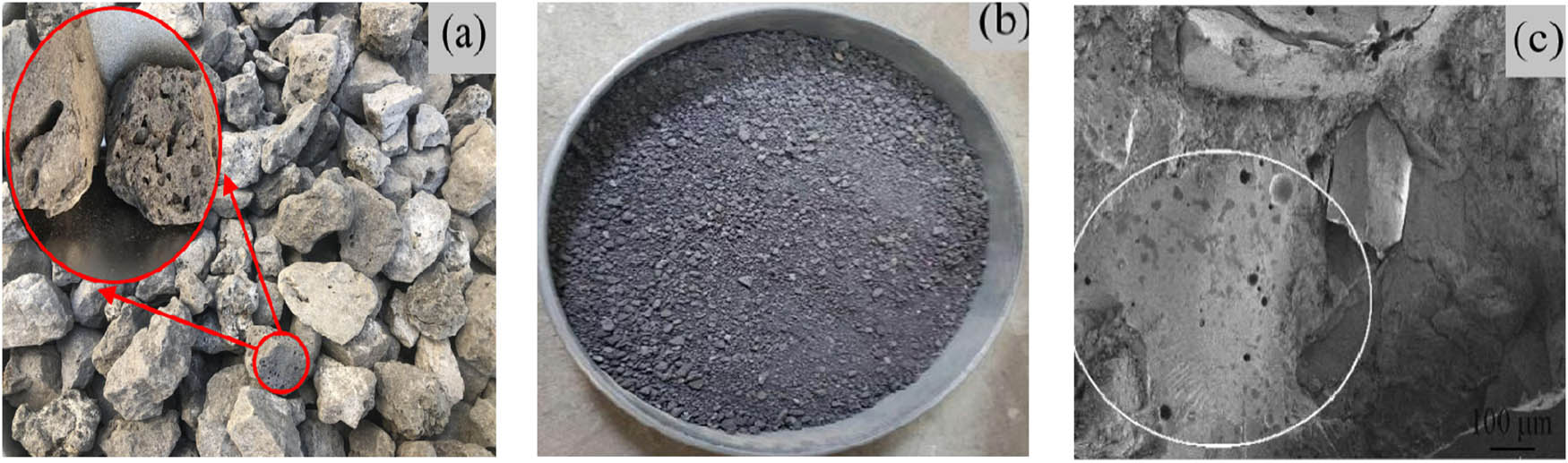
The appearance of SS: (a) SS stone; (b) SS sand; and (c) internal appearance.
In the present investigation, the chemical composition of the SS was analyzed using X-ray fluorescence spectroscopy. The specific composition is detailed in Table 5. The main chemical composition of the SS was similar to that of Portland cement clinker, and it displayed certain cementitious properties. However, when compared with cement clinker, the SSA contained higher iron content, which helped improve such physical properties of the concrete as shrinkage and frost resistance.
Chemical composition of SSA
| Composition | CaO | MgO | Fe2O3 | Al2O3 | SiO2 | F-CaO | Other |
|---|---|---|---|---|---|---|---|
| Mass fraction (%) | 38.89 | 12.14 | 25.28 | 2.70 | 16.20 | 0.64 | 4.15 |
The alkalinity coefficient calculated according to the chemical composition of the SS could then be used to measure the activities. The definition of SS alkalinity in China adopts the method of Mason B [22], in which the alkalinity value can be measured in formula (1).
where R represents alkalinity value (%), ω indicates the content of chemical components (%).
The alkalinity of the SS in this study was determined to be 2.4%, or in the medium alkalinity range. Therefore, the activity of the SS was considered to be good.
The results of this study’s X-ray analysis are shown in Figure 2. The SS contained mineral components such as C3S, C2S, C2F, RO phase (FeO, MnO, MgO, and other solid solutions), and small amounts of residual steel. The silicate minerals were found to be helpful in improving the activity of the SS, as well as the interface properties between the aggregate and the cement. It is known that the RO phase directly affects the stability of SS. SS contains some minerals, such as olivine and rose pyroxene, which makes the wear resistance of SS better than that of ordinary gravel. Therefore, it is considered to be feasible to replace natural aggregates with SS.
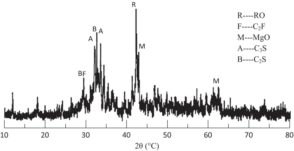
XRD pattern of SSA.
2.2 Mixture proportion
The mix proportions of the C40 ordinary concrete (OC) utilized in this study were designed according to JGJ 55-2011 “Specification for mix proportion design of OC.” Also, the SS was mixed using various proportions. Finally, five groups of SSC with the best content characteristics were selected. The specific mix proportions are detailed in Table 6.
Concrete mix ratio (kg/m3)
| Number | Cement | Fly ash | Fine aggregate | Coarse aggregate | Water | Admixture | ||
|---|---|---|---|---|---|---|---|---|
| aC | 280 | 120 | 768.6 | 0 | 1061.4 | 0 | 170 | 6 |
| SSC20–20 | 280 | 120 | 556.3 | 182 | 907.7 | 280.9 | 170 | 6 |
| bSSC20–40 | 280 | 120 | 556.3 | 182 | 680.8 | 561.9 | 170 | 6 |
| SSC20–60 | 280 | 120 | 556.3 | 182 | 453.8 | 842.8 | 170 | 6 |
| SSC40–20 | 280 | 120 | 417.2 | 364 | 907.7 | 280.9 | 170 | 6 |
| SSC60–20 | 280 | 120 | 278.2 | 546 | 907.7 | 280.9 | 170 | 6 |
aC: Ordinary concrete.
bSSC20–40: Steel slag concrete with 20% steel slag sand and 40% steel slag stone.
2.3 Test method
2.3.1 SS stability test
For the SS stability test, the GB/T24175-2009 “SS stability test method” was referred to, a YZF-2S cement autoclave machine was used to carry out the test, and the stability of the SS was determined by measuring the autoclaved pulverization rates. The principle was that the free CaO and MgO in the SS were autoclaved under 2.0 MPa saturated steam. The stability of the SS was determined by measuring the sizes of the SS digestion pulverization rates. The smaller the rate was, the better the stability of the SS would be.
The experimental steps were as follows:
First, 10 kg SS stone was selected in the 5–25 mm particle size range and completely broken; then crushed through a 9.5 mm square pore sieve; placed in a 105 ± 5°C oven for drying; cooled; and passed through a secondary 4.75 mm square pore sieve screen. Three samples of 800 g were weighed in a 4.75–9.5 mm residue. Then, 10 kg SS sand with particle sizes less than 4.75 mm was selected; oven-dried and cooled; and passed through a 2.36 mm square pore sieve. Samples measuring 2.36–4.75 mm were selected, and three 800 g samples were weighed.
After all of the samples had been washed, they were placed into an autoclave for 3 h. Then, the samples were removed and dried after cooling; weighed; denoted as m 0; passed through a 1.18 mm sieve; and weighed as m 1. The pulverization rate formula was as follows:
(2)where f represents pulverization rate (%), m 0 indicates the mass of samples after test (g), m 1 indicates the mass of samples after passing 1.18 mm sieve (g).
Test results: The average autoclaved pulverization rates of the fractions were 3.31 and 3.55%, respectively. In addition, with references made to YB/T 4201-2009 “SS sand for ordinary ready-mixed mortar” and YB/T 4329-2012 “Application Technology of SS Sand for Cement Concrete Pavement,” both were within 5.9%, which met the requirements of this study.
2.3.2 Freezing-thawing test
The freezing-thawing parameters were tested according to the GB/T 50082-2009 “Standard for test methods of the long-term performance and durability of OC.” An IMDR concrete rapid freezing-thawing machine was used to carry out the freezing-thawing cycle test of the concrete. Specimens in the size range of 100 mm × 100 mm × 400 mm were designed using a fast-freezing method. After 24 days, the specimens were immersed in water at approximately 20°C, then removed after 4 days, and the surface moisture was wiped dry. Prior to testing, the water was required to pass the upper surfaces of the specimens and exceed 5 mm, as shown in Figure 3(a). The freezing-thawing test set 150 cycles. The mass losses and relative dynamic elastic modulus were tested every 25 cycles. The determination of the elastic modulus is shown in Figure 3(b). The testing process could be stopped if one of the following conditions occurs: (1) The freezing-thawing cycles reached a specified number; (2) The relative dynamic modulus of elasticity decreased to 60%; (3) The mass loss rate reached 5%.
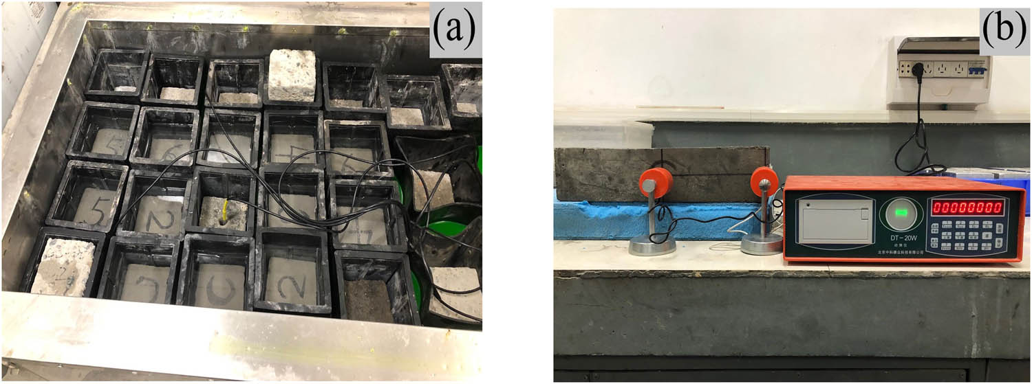
(a) Freezing-thawing specimens and (b) measurement of relative dynamic elastic modulus.
3 Results and analysis
3.1 Experimental phenomena
The failure phenomena observed in this study are shown in Figure 4. From left to right in the figure, (according to the number of freezing-thawing cycles) the observations followed 0, 50, 100, and 150 cycles. It was found that the surfaces of the specimens prior to testing were complete and smooth, and there was dense cement slurry wrapped on the outside. However, when the specimens were removed after the 50th cycle, the cement mortar epidermis outside the OC had begun to fall off. The main reason for this was that, with the increase of freezing-thawing cycles, the micro pores on the surface of OC continued to develop and were converted to large holes, so that the surface of OC was seriously damaged [23]. By comparison, the number of holes on the surfaces of SS was fewer in number. The reason for this was that SS could produce C–S–H gels and fill some of the pores, which could effectively prevent the flow of the aqueous solution, and the hydrostatic pressure or osmotic pressure could be reduced, thereby further reducing the degree of freezing-thawing damage in SSC [24]. When the freezing-thawing cycles were carried out to the 100th cycle, the aggregate was found to be exposed, and the OC was observed to be the most severe. This was due to the repeated freezing-thawing of water in the capillary of concrete, which led to the continuous extension and expansion of cracks, and finally led to the mutual penetration of cracks. At the same time, the completely closed microbubbles began to produce frost heave cracking under the effects of expansion pressure stress and osmotic pressure stress, and the network or flocculent C–S–H gels formed by cement hydration began to increase [25]. Meanwhile, the specimens of the SSC20–60 group only displayed the phenomenon of cement mortar epidermis shedding. When the freezing-thawing was carried out to the 150th cycle, the specimens were found to be damaged to varying degrees. The damages to the OC were the most serious, with even the aggregate falling off. However, the SSC with different dosages only showed the mortar falling off, with the aggregate remaining intact. The main reason for these results was that with the increase of freezing-thawing cycles, aqueous solution continuously enters the concrete and freezing-thawing occurs in the pores. When the expansion pressure produced by ice crystal exceeded the force that concrete could bear, the surface would exhibit a frost heave cracking phenomenon, and a large number of micro-cracks would form on the surface, resulting in the gradual accumulation of damage [26].
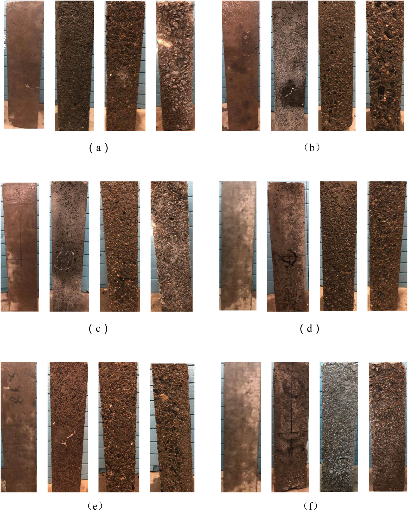
Failure characteristics. (a) C, (b) SSC20–20, (c) SSC20–40, (d) SSC20–60, (e) SSC40–20, and (f) SSC60–20.
In the present research investigation, a comparison of test phenomena after 150 freezing-thawing cycles was made. It was found that the OC was more seriously damaged when compared with the SSC. However, the SSC only underwent shedding of the outsourcing mortar layers, which indicated that SS as an aggregate mixed with concrete could more effectively resist the damages caused by freezing-thawing cycles. The reason for this was that SS could react to the cement hydration producing C–S–H gels, which would play a good filling role, thereby improving the density of SSC [27], so that the hydrostatic pressure or osmotic pressure could be reduced, which resulted in the overall structure being denser [28]. In addition, the interfacial transition zone (ITZ) between SS and cement stone was small, which could form strong interfacial adhesion, so that the overall structure was stabler, thereby further reducing the degree of freezing-thawing damage in SSC [29].
3.2 Microscopic study
Concrete is a kind of porous material, and through the reaction of water and cement, it will form a hardening slurry which can cement sand and stone together, and the original internal space filled by water will not be fully filled by hydration products, which will become pores. These pores are usually referred to as fine pores, and the pore size is generally several nanometers to several microns, which has an important influence on the frost resistance of concrete [30,31]. Therefore, it is necessary to analyze the microstructure of concrete and properties of hydration products in nanospace. A Sigma500 SEM was used to analyze the broken specimens of OC and SSC20–60 in this study; test instruments are shown in Figure 5. The transition zones between the aggregate and the cement stone interfaces, along with the hydration products, are shown in Figures 6 and 7.
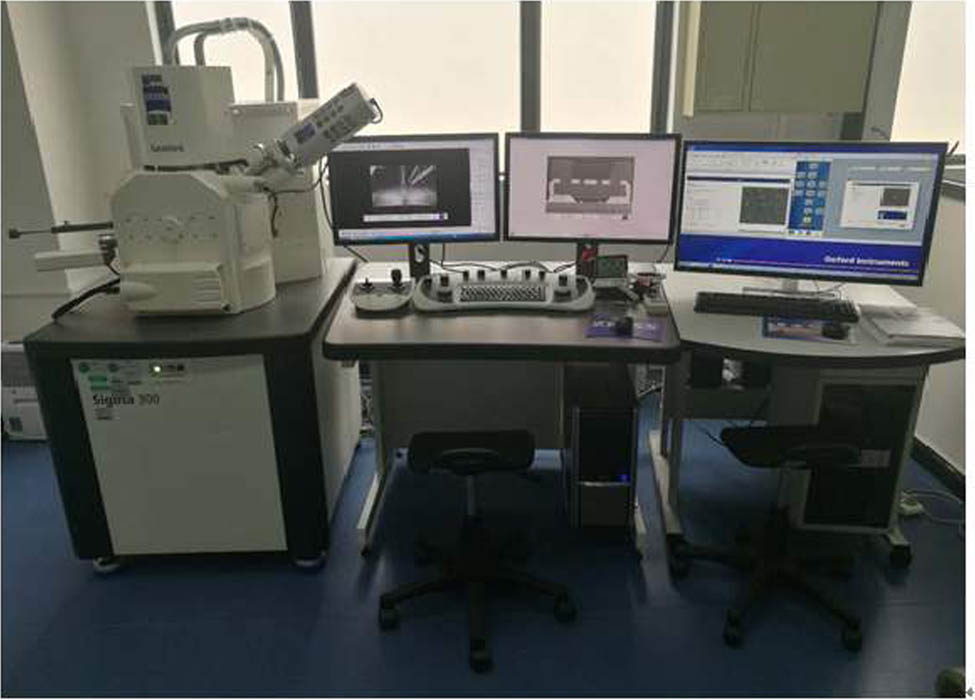
Scanning electron microscope.
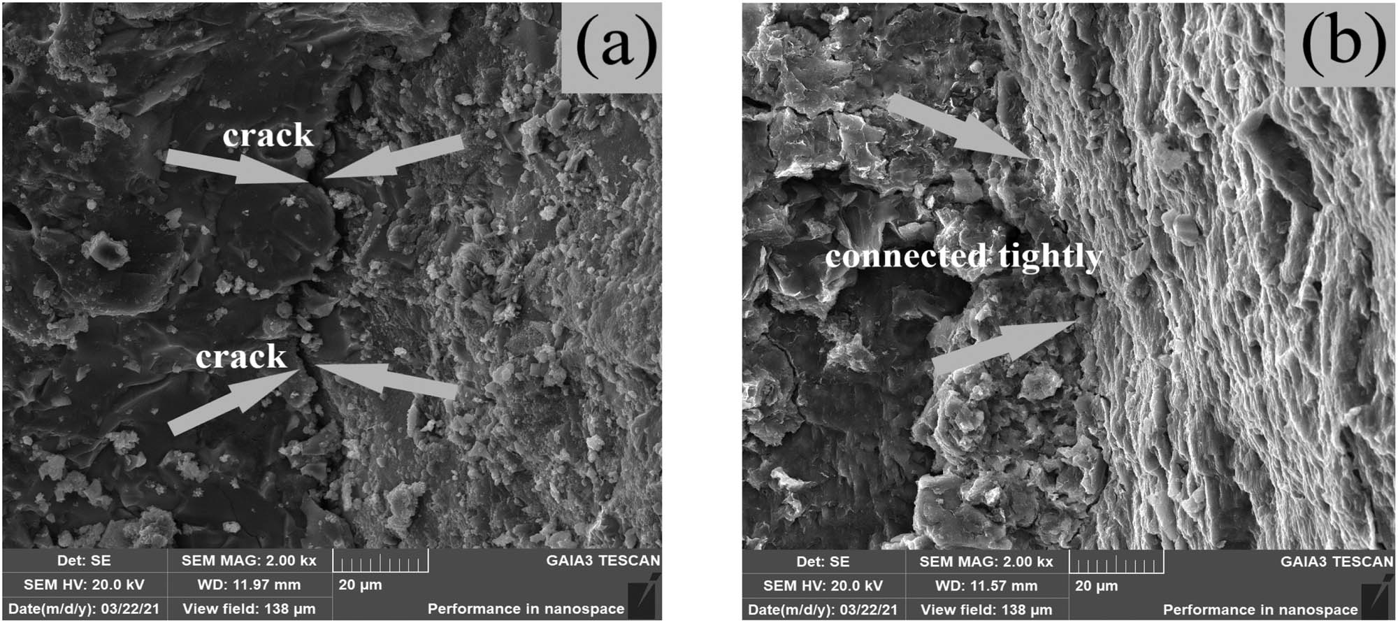
ITZ: (a) C and (b) SSC20–60.
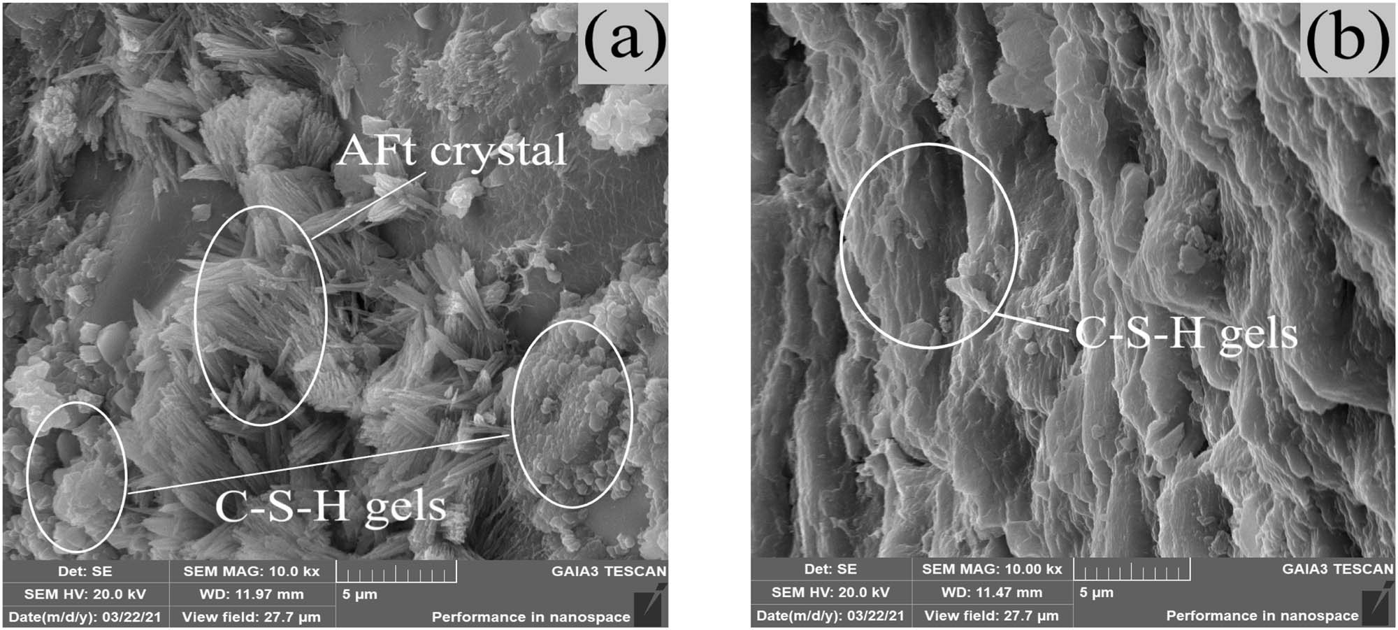
Hydration products: (a) C and (b) SSC20–60.
Figure 6(a) shows that there were obvious micro-cracks about 2 μm wide in the interface transition zone of OC due to the unfavorable bonds between the natural aggregate and the cement paste. With the progress of freezing-thawing cycles, after the aqueous solution entered the concrete, it froze and thawed continuously, and when the expansion pressure generated by ice crystals exceeded the force that the concrete could bear, the performance of the bonding interface between aggregate and cementitious materials in OC would be further seriously damaged [32]. According to the viewpoint of random damage in damage mechanics, the initial damage area of concrete is in ITZ where the connection between crystals can be regarded as a “micro-spring system” [33]. Figure 6(b) shows that the ITZ of SSC20–60 were denser due to the close bonds between the SSA and the cement stone. In other words, the number of “micro-springs” was greater. Therefore, when the two were subjected to the same freezing-thawing damage conditions, the degrees of cracking damage of the SSC were lower and the macroscopic freezing-thawing resistance was better than that of the OC specimens.
Figure 7 shows that the hydration products in the ITZ were mainly coral-like C–S–H gels. It can be seen that the aggregate in Figure 7(a) is surrounded by fibrous and coralline gels which are not sufficiently bound. Besides, with the increase of the freezing-thawing cycles, SO4 2− and the Ca(OH)2 in the cement stone reacted to generate CaSO4, and the CaSO4 would react with hydrated calcium aluminate in cement to generate calcium trisulphoaluminate hydrate (AFt), then the AFt would generate great stress; when the generated stress exceeded the bearing capacity of concrete, the internal micro-cracks of concrete specimens would increase and further develop [34,35,36]. The chemical composition of the SS was similar to that of the cement. Hydration reaction of dicalcium silicate and tricalcium silicate occurred in a later period, and the chemical reaction can be found in formulas (3) and (4). More gels were produced when hydration occurred during the later period, as illustrated in Figure 7(b). There were holes on the surfaces of the SS which allowed the gels and aggregate to be more closely embedded. At the same time, this had also reduced the number of pores and effectively prevented the flow of the aqueous solution [37]. Then, hydrostatic pressure or osmotic pressure could be reduced [38], which resulted in the overall structure being more stable and the frost resistance of the SSC being improved.
3.3 Freeze-thaw resistance
3.3.1 Mass loss
Mass loss rates are important reference factors in the study of concrete freeze-thaw damages; the mass loss rate of concrete specimen after freezing-thawing is calculated according to formula (5). The average value of each group was taken as the final mass loss rate.
where G 0 represents the mass of concrete specimens before freezing-thawing cycles, G n indicates the mass of concrete specimens after N times of freezing-thawing cycles.
Figure 8 shows the mass loss rates of the concrete after 0, 50, 100, and 150 freeze-thaw cycles. At the early stage of the freezing-thawing, the folding lines were all relatively gentle. The main reason for this was that the concrete had been soaked before the freeze-thaw cycles and reached the state of water absorption saturation in theory. Therefore, the mass losses were not obvious at the beginning of the freeze-thaw cycles [39]. When the freeze-thaw tests were carried out to the middle and late stages, the loss rates of each group were found to be significantly higher, which corresponded to the observed appearances of the specimens. This was due to the fact that with the increases of the freezing-thawing cycles,
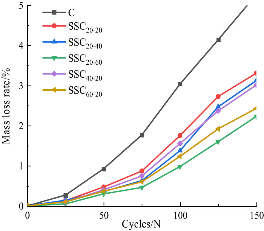
Relation between mass loss rate and freezing-thawing cycles.
3.3.2 Relative dynamic modulus of elasticity analysis
The dynamic elastic modulus of the specimens was tested by DT-20W, and the dynamic elastic modulus of each cycle of each group of specimens was computed using formula (6).
where E 0 represents the dynamic modulus of concrete specimens before freezing-thawing cycles, E n indicates the dynamic modulus of concrete specimens after N times of freezing-thawing cycles.
Figure 9 shows the fractional changes in the relative dynamic modulus of elasticity of the specimens following the freezing-thawing cycles. As the freeze-thaw tests progressed, the relative dynamic modulus of elasticity of the concrete exhibited varying degrees of decline, which indicated that the internal damages were gradually accumulating and intensifying. It was observed that when the number of freeze-thaw cycles reached 50, the internal damages to the specimens in each group were small, and the modulus of dynamic elasticity was maintained above 90%. The reason for this was that aqueous solution continuously entered the interior of concrete, and freezing-thawing occurred in the pores. When the expansion pressure produced by ice crystal exceeded the force that the concrete could bear, the concrete would produce frost heave cracking and form some micro-cracks, thereby resulting in damage [42]. SSC20–40 and SSC20–60 showed the smallest decline in modulus of dynamic elasticity, with almost no change observed. The SSC20–60 Group showed the slowest decline, indicating that the internal damages caused by the freezing-thawing conditions were also small. Then, after 150 freezing-thawing cycles, the modulus of elasticity decreased to 62.3%, which was close to the specified value of 60%, at which point the specimens were considered to be damaged. The main reason for these results was that the increase of freezing-thawing cycles and the repeated freezing-thawing of aqueous solution in the capillary of concrete led to the continuous extension and expansion of cracks, and finally to the mutual penetration of cracks, so that the concrete was seriously damaged [43]. However, the SSC20–20 Group decreased to 74.92%, and the other SSC were more than 80%, indicating good performance in terms of frost resistance. This study determined that the decreases of the relative dynamic elastic modulus of SSC specimen groups were as follows: SSC20–20: 25.08%; SSC20–40: 16.88%; SSC20–60: 8.91%; SSC40–20: 18.73%; and SSC60–20: 15.41%. The relative dynamic modulus of the SSC decreased with the increases in the freezing-thawing cycles. However, the relative dynamic modulus decreased less with the increase of SS content. The bonding interfaces of the SSA and the cement slurry were better than those of the ordinary aggregate and the cement slurry. Therefore, when the concrete specimens were at the same freezing-thawing damage degree, the cracking damages were smaller and the frost resistance was better.
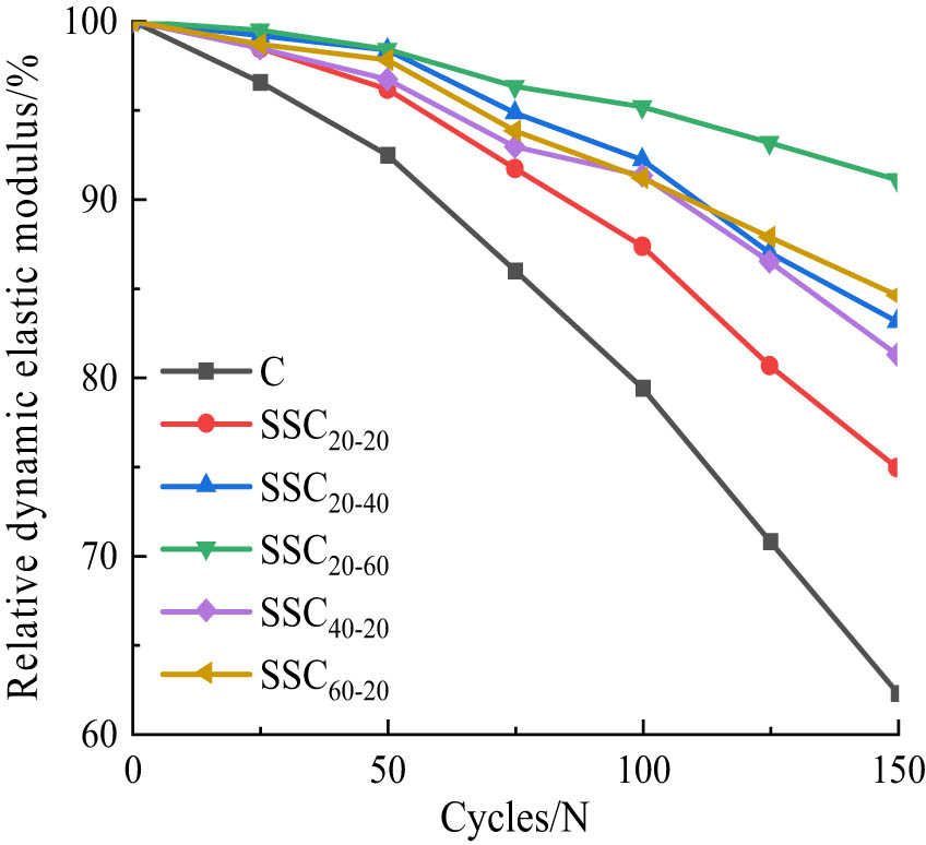
Relationship between relative dynamic elastic modulus and freezing-thawing cycles.
3.3.3 Freezing-thawing damage model and life prediction based on relative dynamic elastic modulus
In order to investigate the causes of the freezing-thawing damages to SSC, this study conducted an analysis based on the gradual accumulation of small internal damages using a damage mechanics theory as the basis. The freeze-thaw damage process could be expressed as follows: (1) Micro-cracks were generated within the concrete; (2) Macro-cracks appeared; and (3) Matrix damages occurred [44]. During the experimental tests, concrete cracking had occurred after water absorption resulting in increases in the masses of the specimens. The relative dynamic modulus of elasticity was used as a variable in order to respond to the degrees of freezing-thawing damage (D) to SSC. The equation was as follows:
In formula (7), D denotes the degree of concrete damage; E 0 represents initial dynamic modulus; and E α indicates dynamic modulus after freezing-thawing test. Based on the above equation and with reference to the literature [45,46], a quadratic and exponential function is chosen to express the freeze-thaw damage model; the models are depicted in Table 7.
Damage calculation model
| Unary quadratic function |
|
| Exponential function |
|
E α /E 0: The relative dynamic elastic modulus of concrete. a, b, c: the correlation coefficients.
N: The freezing-thawing cycle coefficient.
The fitting results are shown in Tables 8 and 9. It can be seen from the tables that the fitting accuracy R 2 of the quadratic function was between 0.982 and 0.999. The fitting accuracy R 2 of the exponential function was between 0.926 and 0.960. Therefore, the quadratic function model was able to better reflect the freezing-thawing damage law of the SSC.
Results of fitting parameters of exponential function
| Test specimen number | a | b | R 2 |
|---|---|---|---|
| C | 1.02833 | −2.94 × 10⁻³ | 0.946 |
| SSC20–20 | 1.0234 | −1.84 × 10⁻³ | 0.930 |
| SSC20–40 | 1.01809 | −1.25 × 10⁻³ | 0.932 |
| SSC20–60 | 1.00687 | −6.19 × 10⁻⁴ | 0.960 |
| SSC40–20 | 1.01627 | −1.31 × 10⁻³ | 0.926 |
| SSC60–20 | 1.01485 | −1.09 × 10⁻³ | 0.934 |
Results of the fitted parameters of the quadratic function
| Test specimen number | a | b | c | R 2 |
|---|---|---|---|---|
| C | −9.58 × 10⁻⁶ | −1.090 × 10⁻³ | 1.00074 | 0.999 |
| SSC20–20 | −8.63 × 10⁻⁶ | −3.869 × 10⁻⁴ | 1.00070 | 0.999 |
| SSC20–40 | −5.36 × 10⁻⁶ | −3.744 × 10⁻⁴ | 1.00398 | 0.982 |
| SSC20–60 | −2.51 × 10⁻⁶ | −2.225 × 10⁻⁴ | 1.00037 | 0.999 |
| SSC40–20 | −6.79 × 10⁻⁶ | −2.133 × 10⁻⁴ | 0.99873 | 0.998 |
| SSC60–20 | −5.52 × 10⁻⁶ | −2.076 × 10⁻⁴ | 1.00062 | 0.999 |
Figure 10 reveals the curve fitting of the relative dynamic elastic modulus of the quadratic function of the SSC. According to the model, the freeze-thaw cycles of the SSC could be calculated when the relative dynamic elastic modulus decreased to 60%. The results are detailed in Table 9. According to ref. [47], the annual average numbers of freezing-thawing cycles in northern China are as follows: 84× in the north; 118× in the northwest; and 120× in the northeast.
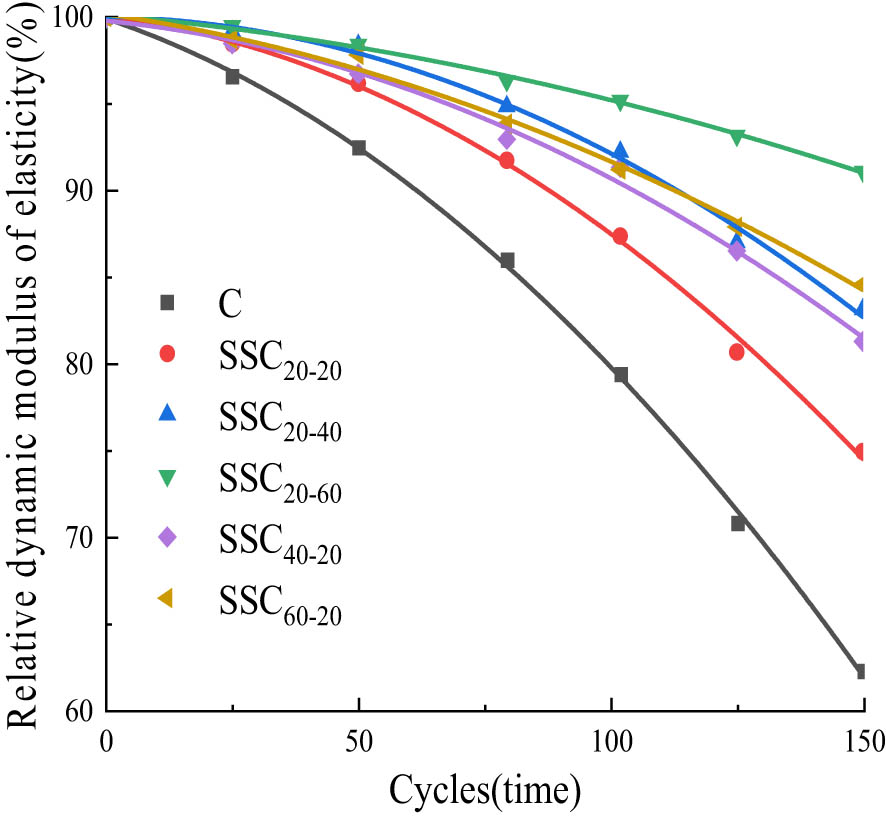
Fitting curves of relative dynamic elastic modulus and freezing-thawing cycles.
After improving upon the lifespan prediction model of Vesikari [48], the relationship between freezing-thawing cycles and the service life is proposed. Then, after referring to a large number of data, the value of the conversion coefficient k of the number of indoor and outdoor freezing and thawing cycles was summarized [49,50].
where t represents the service life of concrete, k indicates the rapid freezing-thawing coefficient in the laboratory, taken as 1:8 in this paper, i.e., number of the freeze-thaw cycles indoor equivalent to 8× of the natural environment, M indicates the number of freeze-thaw cycles that concrete structures may undergo in the natural environment, and N indicates the number of freezing-thawing cycles of concrete when the relative dynamic elastic modulus is decreased to 60%.
According to the number of freeze-thaw cycles and prediction model of concrete in Table 10, the durability life of concrete in northern regions can be obtained, and the results are shown in Table 11.
Number of frozen and melting circulation of concrete when the relative dynamic elastic modulus reached 60% (N)
| Specimen number | C | SSC20–20 | SSC20–40 | SSC20–60 | SSC40–20 | SSC60–20 |
|---|---|---|---|---|---|---|
| Number of freezing-thawing cycles | 155 | 194 | 242 | 357 | 227 | 250 |
Freezing-thawing cycle life of concrete when the relative dynamic elastic modulus reached 60% (years)
| Numbering | C | SSC20–20 | SSC20–40 | SSC20–60 | SSC40–20 | SSC60–20 |
|---|---|---|---|---|---|---|
| North-east area | 10.3 | 12.9 | 16.1 | 23.8 | 15.1 | 16.7 |
| North-west region | 10.5 | 13.2 | 16.4 | 24.2 | 15.4 | 16.9 |
| North China | 14.8 | 18.5 | 23.0 | 34.0 | 21.6 | 23.8 |
In Table 11, the anti-freezing-thawing lifespans of different specimens were measured in years. The freezing-thawing lifespan of the SSC with different dosages in northern China had increased. The anti-freezing-thawing lifespans of the SSC were greatly improved when compared with those of the OC. The freezing-thawing lifespan of concrete in the Group SSC20–60 was more than twice that of the OC. In addition, when compared with the OC, the freezing-thawing life durability of the SSC specimens had been greatly improved, which indicated that the incorporation of SS as an aggregate was an effective method for improving the anti-freezing-thawing durability of concrete.
4 Conclusion
Appropriate increases in the amount of SSA could effectively improve the frost resistance of concrete, and the frost resistance of SSC20–60 was superior to that of the other examined groups.
The performance of OC and SSC20–60 was analyzed in nanospace to research the damage mechanisms. It was concluded that the high density of SSC can effectively inhibit the aqueous solution into the concrete, thereby avoiding the damage to the concrete caused by the expansion pressure formed by the ice crystals. Therefore, SSC20–60 exhibited better frost resistance durability.
A freeze-thaw damage calculation model of SSC was established with the relative dynamic elastic modulus as the variable. It was found that the freezing-thawing durability lifespans of the SSC20–60 and SSC60–20 were longer, at 357 and 250 cycles, respectively. It was observed that after adding a certain amount of SS to the concrete specimens, the freezing-thawing durability lifespans were significantly improved when compared with OC.
Combined with the average number of freeze-thaw times in northern China, the freeze-thaw durability of SSC was predicted according to the damage calculation model. It was concluded that SSC had better freeze-thaw durability, and the freeze-thaw cycle lifespan of SSC20–60 was predicted to be longer than that of OC, at more than twice that of the OC. The results confirmed that the concrete prepared with SS as an aggregate could achieve improved freezing-thawing durability, which provided a reference for the future application of SSC in practical engineering projects.
A freezing-thawing damage calculation model was established in this study by using the relative dynamic elasticity as a variable. It was found that the accuracy of its correlation coefficient values could reach more than 0.982. Therefore, the model established in this study was considered to have significant reference value for the prediction of frost resistance durability lifespans of SSC in cold regions.
Acknowledgements
One of the authors (H. S.) is thankful to his teacher's help and guidance and thanks his girlfriend Wang Siqi's for encouragement and support.
-
Funding information: This study was funded by the National Natural Science Foundation of China (grant no. 51768056).
-
Author contributions: Manuscript writing and data analysis mainly completed by Hui SUN, all authors have accepted responsibility for the entire content of this manuscript and approved its submission.
-
Conflict of interest: The authors state no conflict of interest.
-
Data availability statement: All data, models, and code generated or used during the study appear in the submitted article.
References
[1] USGS. Iron and steel slag statistics and information. Accessed 06/05/2015.Suche in Google Scholar
[2] Guo J, Bao Y, Wang M. Steel slag in China: treatment, recycling, and management. Waste Manag. 2018;78:318–30.10.1016/j.wasman.2018.04.045Suche in Google Scholar
[3] Olofinnade O, Morawo A, Okedairo O, Kim B. Solid waste management in developing countries: Reusing of steel slag aggregate in eco-friendly interlocking concrete paving blocks production. Case Stud Constr Mater. 2021;14:e00532.10.1016/j.cscm.2021.e00532Suche in Google Scholar
[4] Maslehuddin M, Sharif AM, Shameem M, Ibrahim M, Barry MS. Comparison of properties of steel slag and crushed limestone aggregate concretes. Constr Build Mater. 2003;17(2):105–12.10.1016/S0950-0618(02)00095-8Suche in Google Scholar
[5] Liuchunlin Zha, Kunpeng Chen. Depeng, possibility of concrete prepared with steel slag as fine and coarse aggregates: a preliminary study. Procedia Eng. 2011;4:412–6.10.1016/j.proeng.2011.11.2667Suche in Google Scholar
[6] Anastasiou E, Papayianni I. Criteria for the use of steel slag aggregate in concrete. M. S. Konsta-Gdoutos. Measuring, monitoring and modeling concrete properties. Netherlands: Springer; 2006. p. 419–26.10.1007/978-1-4020-5104-3_51Suche in Google Scholar
[7] Furlani E, Tonello G, Maschio S. Recycling of steel slag and glass cullet from energy saving lamps by fast firing production of ceramics. Waste Manag. 2010;30:1714–9.10.1016/j.wasman.2010.03.030Suche in Google Scholar PubMed
[8] Wu W, Zhang W, Ma G. Optimum content of copper slag as a fine aggregate in high strength concrete. Mater Des. 2010;31:2878–83.10.1016/j.matdes.2009.12.037Suche in Google Scholar
[9] Subathra Devi V, Gnanavel BK. Properties of concrete manufactured using steel slag. Procedia Eng. 2014;97:95–104.10.1016/j.proeng.2014.12.229Suche in Google Scholar
[10] Chunlin L, Kunpeng Z, Depeng C. Possibility of concrete prepared with steel slag as fine and coarse aggregates: a preliminary study. Procedia Eng. 2011;24:412–6.10.1016/j.proeng.2011.11.2667Suche in Google Scholar
[11] Wang S, Zhang G, Wang B, Wu M. Mechanical strengths and durability properties of pervious concretes with blended steel slag and natural aggregate. J Clean Prod. 20 October 2020;271:122590.10.1016/j.jclepro.2020.122590Suche in Google Scholar
[12] Fagerlund G. A service life model for internal frost damage in concrete, Div. Building materials, Lund Institute of Technology; 2004. Report TVBM-3119.Suche in Google Scholar
[13] Liu M, Wang Y. Damage constitutive model of fly ash concrete under freeze-thaw cycles. J Mater Civ Eng. 2012;24(9):1165–74.10.1061/(ASCE)MT.1943-5533.0000491Suche in Google Scholar
[14] Duan A, Jin W, Qian J. Effect of freeze-thaw cycles on the stress-strain curves of unconfined and confined concrete. Mater Struct. 2011;44:1309–24.10.1617/s11527-010-9702-9Suche in Google Scholar
[15] Duan A, Tian Y, Dai JG, Jin WL. A stochastic damage model for evaluating the internal deterioration of concrete due to freezing-thawing action. Mater Struct. 2014;47:1025–39.10.1617/s11527-013-0111-8Suche in Google Scholar
[16] Penttala V. Surface and internal deterioration of concrete due to saline and non-saline freezing-thawing loads. Cem Concr Rer. 2006;36(5):921–8.10.1016/j.cemconres.2005.10.007Suche in Google Scholar
[17] Zhang X, Wang L, Zhang J. Mechanical behavior and chloride penetration of high strength concrete under freezing-thawing attack. Cold Reg Sci Technol. 2017;142:17–24.10.1016/j.coldregions.2017.07.004Suche in Google Scholar
[18] Cao DF, Fu LZ, Yang ZW. Test study on tensile properties of concrete after freezing-thawing cycles. J Buil Mater. 2012;15(1):48–52.Suche in Google Scholar
[19] Liu MH, Wang YF. Damage constitutive model of fly ash concrete under freeze-thaw cycles. J Mater Civ Eng. 2012;24(9):1165–74.10.1061/(ASCE)MT.1943-5533.0000491Suche in Google Scholar
[20] Paolo F. Analytical model to predict the lifetime of concrete members externally reinforced with FRP. Theor Appl Fract Mec. 2015;75:137–45.10.1016/j.tafmec.2014.12.002Suche in Google Scholar
[21] Sun W, Zhang YM, Yan HD, Mu R. Damage and resistance of high strength concrete under the action of load and freezing-thawing cycle. Cem Concr Res. 1999;29:1519–23.10.1016/S0008-8846(99)00097-6Suche in Google Scholar
[22] Mason B. The constitution of some open-heart slag. J Iron steel Inst. 1994;11:69–80.Suche in Google Scholar
[23] Yu H, Ma H, Yan K. An equation for determining freeze-thaw fatigue damage in concrete and a model for predicting the service life. Constr Build Mater. 2017;137:104–16.10.1016/j.conbuildmat.2017.01.042Suche in Google Scholar
[24] Gao C, Shen XD, Wang XX. Freezing-thawing resistance of lightweight aggregate concrete with stress damage. J Chin Ceram Soc. 2014;42(10):1247–52.Suche in Google Scholar
[25] Chenxia W, Lu L, Fubo C, Lan L. Experimental study on mechanical properties of recycled concrete after freeze-thaw cycles. J Build Struct. 2020;41(12):193–202. (In Chinese).Suche in Google Scholar
[26] Meiyan H, Minghui J, Wenlei Z, Yubin Y, Teng C, Hao W. Composite salt corrosion deterioration characteristics and damage calculation models of concrete incorporated with corrosion inhibiting admixtures. J Build Eng. 2021;44(1):103221.10.1016/j.jobe.2021.103221Suche in Google Scholar
[27] Ali K, Qureshi MI, Saleem S, Khan SU. Effect of waste electronic plastic and silica fume on mechanical properties and thermal performance of concrete. Constr Build Mater. 2021;285(11):122952.10.1016/j.conbuildmat.2021.122952Suche in Google Scholar
[28] Qin XC, Meng SP, Cao DF, Tu YM, Sabourova N, Grip N. Evaluation of freezing-thawing damage on concrete material and prestressed concrete specimens. Constr Build Mater. 2016;125:892–904.10.1016/j.conbuildmat.2016.08.098Suche in Google Scholar
[29] Liu L, Wang XC, Zhou J, Chu HQ, Shen DJ, Chen HS, et al. Investigation of pore structure and mechanical property of cement paste subjected to the coupled action of freezing/thawing and calcium leaching. Cem Concr Res. 2018;109:133–46.10.1016/j.cemconres.2018.04.015Suche in Google Scholar
[30] Mehta PK, Monteiro PJ. Concrete: microstructure, properties and materials. 3rd edn. New York: McGraw-Hill; 2006.Suche in Google Scholar
[31] Pigeon M, Pleau R. Durability of concrete in cold climates. 1st edn. London: E&FNSPON; 1995.Suche in Google Scholar
[32] Wang B, Pan J, Fang R, Wang Q. Damage model of concrete subjected to coupling chemical attacks and freeze-thaw cycles in saline soil area. Constr Build Mater. 2020 May 10;242:118205.10.1016/j.conbuildmat.2020.118205Suche in Google Scholar
[33] Liu CH, Wan JP. Probability theory and mathematical statistics. Beijing: Higher Education Press; 2001 (In Chinese).Suche in Google Scholar
[34] Fan XC, Wu D, Chen H. Experimental research on the freezing-thawing resistance of basalt fiber reinforced concrete. Adv Mat Res. 2014;919–921:1912–5.10.4028/www.scientific.net/AMR.919-921.1912Suche in Google Scholar
[35] Guo K, Ma HH, Yang FS, Zhao TY. Micromechanical properties of GO-RC interface transition zone under Freeze-Thaw cycle. J Build Mater. 2020;1(23):230–8 (In Chinese).Suche in Google Scholar
[36] Chen JX, Deng XH, Luo YB, He LC, Liu Q, Qiao X. Investigation of microstructural damage in shotcrete under a freeze–thaw environment. Constr Build Mater. 2015;83:275–82.10.1016/j.conbuildmat.2015.02.042Suche in Google Scholar
[37] Bullard JW, Jennings HM, Livingston RA, Nonat A, Scherer GW, Schweitzer JS, et al. Mechanisms of cement hydration. Cem Concr Res. 2011;41(12):1208–23.10.1016/j.cemconres.2010.09.011Suche in Google Scholar
[38] Powers TC. A working hypothesis for further studies of frost resistance. J Am Concr Inst. 1945;16(4):245–72.Suche in Google Scholar
[39] Wang BX, Wang F, Wang Q. Damage constitutive models of concrete under the coupling action of freezing-thawing cycles and load based on Lemaitre assumption. Constr Build Mater. 2018;173:332–41.10.1016/j.conbuildmat.2018.04.054Suche in Google Scholar
[40] Hang MY, Cui L, Wu JQ, Sun ZK. Freezing-thawing damage characteristics and calculation models of aerated concrete. J Build Eng. 2020;28:101072.10.1016/j.jobe.2019.101072Suche in Google Scholar
[41] Li B, Mao JZ, Shen WG, Liu HB, Liu XZ, Xu GL. Mesoscopic cracking model of cement-based materials subjected to freeze-thaw cycles. Constr Build Mater. 2019;211:1050–64.10.1016/j.conbuildmat.2019.03.266Suche in Google Scholar
[42] Powers TC. Resistance to weathering-freezing and thawing. Portland Cement Assoc R&D Lab Bull; 1900.Suche in Google Scholar
[43] Qiu J, Zhou Y, Vatin NI, Guan X, Sultanov S, Khemarak K. Damage constitutive model of coal gangue concrete under freeze-thaw cycles. Constr Build Mater. 20 December 2020;264:120720.10.1016/j.conbuildmat.2020.120720Suche in Google Scholar
[44] Fu YW, Cai LC, Cao DG. Study on freeze thaw durability and damage model of alkali activated slag high performance concrete. Eng Mech. 2012;23(3):103–9 (In Chinese).Suche in Google Scholar
[45] Liu L, Xu SX, Chen HS, Zhao HT. Numerical investigation of the effects of freezing on micro-internal damage and macro-mechanical properties of cement pastes. Cold Reg Sci Technol. 2014;106–107(10):141–52.10.1016/j.coldregions.2014.07.003Suche in Google Scholar
[46] Niu JG, Zuo FL, Wang JL. Freeze thaw damage model of plastic steel fiber reinforced lightweight aggregate concrete. J Build Mater. 2018;21(2):235–40 (In Chinese).Suche in Google Scholar
[47] Zhang RF, Wang X, Fan HM, Zhou LL, Wu M, Liu YH. Study on the division of freezing-thawing zones and the characteristics of zoning erosion in China. Sci Soil Water Conserv China. 2009;7(2):24–8 (In Chinese).Suche in Google Scholar
[48] Vesikari E. Service life design of concrete structures with regard to the frost resistance of concrete. Nordic Concr Res. 1986;5:215–28.Suche in Google Scholar
[49] Li J, Peng XP, Deng ZG. Quantitative design on the frost resistance of concrete. Concrete. 2000;12:61–5. (In Chinese).Suche in Google Scholar
[50] Wu HR, Jin WL, Yan YD. Freeze thaw environment zoning and frost resistance life prediction of concrete. J Zhejiang Univ (Eng edn). 2012;46(4):650–7 (In Chinese).Suche in Google Scholar
© 2021 Yang Wen et al., published by De Gruyter
This work is licensed under the Creative Commons Attribution 4.0 International License.
Artikel in diesem Heft
- Research Articles
- Improved impedance matching by multi-componential metal-hybridized rGO toward high performance of microwave absorption
- Pure-silk fibroin hydrogel with stable aligned micropattern toward peripheral nerve regeneration
- Effective ion pathways and 3D conductive carbon networks in bentonite host enable stable and high-rate lithium–sulfur batteries
- Fabrication and characterization of 3D-printed gellan gum/starch composite scaffold for Schwann cells growth
- Synergistic strengthening mechanism of copper matrix composite reinforced with nano-Al2O3 particles and micro-SiC whiskers
- Deformation mechanisms and plasticity of ultrafine-grained Al under complex stress state revealed by digital image correlation technique
- On the deformation-induced grain rotations in gradient nano-grained copper based on molecular dynamics simulations
- Removal of sulfate from aqueous solution using Mg–Al nano-layered double hydroxides synthesized under different dual solvent systems
- Microwave-assisted sol–gel synthesis of TiO2-mixed metal oxide nanocatalyst for degradation of organic pollutant
- Electrophoretic deposition of graphene on basalt fiber for composite applications
- Polyphenylene sulfide-coated wrench composites by nanopinning effect
- Thermal conductivity and thermoelectric properties in 3D macroscopic pure carbon nanotube materials
- An effective thermal conductivity and thermomechanical homogenization scheme for a multiscale Nb3Sn filaments
- Friction stir spot welding of AA5052 with additional carbon fiber-reinforced polymer composite interlayer
- Improvement of long-term cycling performance of high-nickel cathode materials by ZnO coating
- Quantum effects of gas flow in nanochannels
- An approach to effectively improve the interfacial bonding of nano-perfused composites by in situ growth of CNTs
- Effects of nano-modified polymer cement-based materials on the bending behavior of repaired concrete beams
- Effects of the combined usage of nanomaterials and steel fibres on the workability, compressive strength, and microstructure of ultra-high performance concrete
- One-pot solvothermal synthesis and characterization of highly stable nickel nanoparticles
- Comparative study on mechanisms for improving mechanical properties and microstructure of cement paste modified by different types of nanomaterials
- Effect of in situ graphene-doped nano-CeO2 on microstructure and electrical contact properties of Cu30Cr10W contacts
- The experimental study of CFRP interlayer of dissimilar joint AA7075-T651/Ti-6Al-4V alloys by friction stir spot welding on mechanical and microstructural properties
- Vibration analysis of a sandwich cylindrical shell in hygrothermal environment
- Water barrier and mechanical properties of sugar palm crystalline nanocellulose reinforced thermoplastic sugar palm starch (TPS)/poly(lactic acid) (PLA) blend bionanocomposites
- Strong quadratic acousto-optic coupling in 1D multilayer phoxonic crystal cavity
- Three-dimensional shape analysis of peripapillary retinal pigment epithelium-basement membrane layer based on OCT radial images
- Solvent regulation synthesis of single-component white emission carbon quantum dots for white light-emitting diodes
- Xanthate-modified nanoTiO2 as a novel vulcanization accelerator enhancing mechanical and antibacterial properties of natural rubber
- Effect of steel fiber on impact resistance and durability of concrete containing nano-SiO2
- Ultrasound-enhanced biosynthesis of uniform ZnO nanorice using Swietenia macrophylla seed extract and its in vitro anticancer activity
- Temperature dependence of hardness prediction for high-temperature structural ceramics and their composites
- Study on the frequency of acoustic emission signal during crystal growth of salicylic acid
- Controllable modification of helical carbon nanotubes for high-performance microwave absorption
- Role of dry ozonization of basalt fibers on interfacial properties and fracture toughness of epoxy matrix composites
- Nanosystem’s density functional theory study of the chlorine adsorption on the Fe(100) surface
- A rapid nanobiosensing platform based on herceptin-conjugated graphene for ultrasensitive detection of circulating tumor cells in early breast cancer
- Improving flexural strength of UHPC with sustainably synthesized graphene oxide
- The role of graphene/graphene oxide in cement hydration
- Structural characterization of microcrystalline and nanocrystalline cellulose from Ananas comosus L. leaves: Cytocompatibility and molecular docking studies
- Evaluation of the nanostructure of calcium silicate hydrate based on atomic force microscopy-infrared spectroscopy experiments
- Combined effects of nano-silica and silica fume on the mechanical behavior of recycled aggregate concrete
- Safety study of malapposition of the bio-corrodible nitrided iron stent in vivo
- Triethanolamine interface modification of crystallized ZnO nanospheres enabling fast photocatalytic hazard-free treatment of Cr(vi) ions
- Novel electrodes for precise and accurate droplet dispensing and splitting in digital microfluidics
- Construction of Chi(Zn/BMP2)/HA composite coating on AZ31B magnesium alloy surface to improve the corrosion resistance and biocompatibility
- Experimental and multiscale numerical investigations on low-velocity impact responses of syntactic foam composites reinforced with modified MWCNTs
- Comprehensive performance analysis and optimal design of smart light pole for cooperative vehicle infrastructure system
- Room temperature growth of ZnO with highly active exposed facets for photocatalytic application
- Influences of poling temperature and elongation ratio on PVDF-HFP piezoelectric films
- Large strain hardening of magnesium containing in situ nanoparticles
- Super stable water-based magnetic fluid as a dual-mode contrast agent
- Photocatalytic activity of biogenic zinc oxide nanoparticles: In vitro antimicrobial, biocompatibility, and molecular docking studies
- Hygrothermal environment effect on the critical buckling load of FGP microbeams with initial curvature integrated by CNT-reinforced skins considering the influence of thickness stretching
- Thermal aging behavior characteristics of asphalt binder modified by nano-stabilizer based on DSR and AFM
- Building effective core/shell polymer nanoparticles for epoxy composite toughening based on Hansen solubility parameters
- Structural characterization and nanoscale strain field analysis of α/β interface layer of a near α titanium alloy
- Optimization of thermal and hydrophobic properties of GO-doped epoxy nanocomposite coatings
- The properties of nano-CaCO3/nano-ZnO/SBR composite-modified asphalt
- Three-dimensional metallic carbon allotropes with superhardness
- Physical stability and rheological behavior of Pickering emulsions stabilized by protein–polysaccharide hybrid nanoconjugates
- Optimization of volume fraction and microstructure evolution during thermal deformation of nano-SiCp/Al–7Si composites
- Phase analysis and corrosion behavior of brazing Cu/Al dissimilar metal joint with BAl88Si filler metal
- High-efficiency nano polishing of steel materials
- On the rheological properties of multi-walled carbon nano-polyvinylpyrrolidone/silicon-based shear thickening fluid
- Fabrication of Ag/ZnO hollow nanospheres and cubic TiO2/ZnO heterojunction photocatalysts for RhB degradation
- Fabrication and properties of PLA/nano-HA composite scaffolds with balanced mechanical properties and biological functions for bone tissue engineering application
- Investigation of the early-age performance and microstructure of nano-C–S–H blended cement-based materials
- Reduced graphene oxide coating on basalt fabric using electrophoretic deposition and its role in the mechanical and tribological performance of epoxy/basalt fiber composites
- Effect of nano-silica as cementitious materials-reducing admixtures on the workability, mechanical properties and durability of concrete
- Machine-learning-assisted microstructure–property linkages of carbon nanotube-reinforced aluminum matrix nanocomposites produced by laser powder bed fusion
- Physical, thermal, and mechanical properties of highly porous polylactic acid/cellulose nanofibre scaffolds prepared by salt leaching technique
- A comparative study on characterizations and synthesis of pure lead sulfide (PbS) and Ag-doped PbS for photovoltaic applications
- Clean preparation of washable antibacterial polyester fibers by high temperature and high pressure hydrothermal self-assembly
- Al 5251-based hybrid nanocomposite by FSP reinforced with graphene nanoplates and boron nitride nanoparticles: Microstructure, wear, and mechanical characterization
- Interlaminar fracture toughness properties of hybrid glass fiber-reinforced composite interlayered with carbon nanotube using electrospray deposition
- Microstructure and life prediction model of steel slag concrete under freezing-thawing environment
- Synthesis of biogenic silver nanoparticles from the seed coat waste of pistachio (Pistacia vera) and their effect on the growth of eggplant
- Study on adaptability of rheological index of nano-PUA-modified asphalt based on geometric parameters of parallel plate
- Preparation and adsorption properties of nano-graphene oxide/tourmaline composites
- A study on interfacial behaviors of epoxy/graphene oxide derived from pitch-based graphite fibers
- Multiresponsive carboxylated graphene oxide-grafted aptamer as a multifunctional nanocarrier for targeted delivery of chemotherapeutics and bioactive compounds in cancer therapy
- Piezoresistive/piezoelectric intrinsic sensing properties of carbon nanotube cement-based smart composite and its electromechanical sensing mechanisms: A review
- Smart stimuli-responsive biofunctionalized niosomal nanocarriers for programmed release of bioactive compounds into cancer cells in vitro and in vivo
- Photoremediation of methylene blue by biosynthesized ZnO/Fe3O4 nanocomposites using Callistemon viminalis leaves aqueous extract: A comparative study
- Study of gold nanoparticles’ preparation through ultrasonic spray pyrolysis and lyophilisation for possible use as markers in LFIA tests
- Review Articles
- Advance on the dispersion treatment of graphene oxide and the graphene oxide modified cement-based materials
- Development of ionic liquid-based electroactive polymer composites using nanotechnology
- Nanostructured multifunctional electrocatalysts for efficient energy conversion systems: Recent perspectives
- Recent advances on the fabrication methods of nanocomposite yarn-based strain sensor
- Review on nanocomposites based on aerospace applications
- Overview of nanocellulose as additives in paper processing and paper products
- The frontiers of functionalized graphene-based nanocomposites as chemical sensors
- Material advancement in tissue-engineered nerve conduit
- Carbon nanostructure-based superhydrophobic surfaces and coatings
- Functionalized graphene-based nanocomposites for smart optoelectronic applications
- Interfacial technology for enhancement in steel fiber reinforced cementitious composite from nano to macroscale
- Metal nanoparticles and biomaterials: The multipronged approach for potential diabetic wound therapy
- Review on resistive switching mechanisms of bio-organic thin film for non-volatile memory application
- Nanotechnology-enabled biomedical engineering: Current trends, future scopes, and perspectives
- Research progress on key problems of nanomaterials-modified geopolymer concrete
- Smart stimuli-responsive nanocarriers for the cancer therapy – nanomedicine
- An overview of methods for production and detection of silver nanoparticles, with emphasis on their fate and toxicological effects on human, soil, and aquatic environment
- Effects of chemical modification and nanotechnology on wood properties
- Mechanisms, influencing factors, and applications of electrohydrodynamic jet printing
- Application of antiviral materials in textiles: A review
- Phase transformation and strengthening mechanisms of nanostructured high-entropy alloys
- Research progress on individual effect of graphene oxide in cement-based materials and its synergistic effect with other nanomaterials
- Catalytic defense against fungal pathogens using nanozymes
- A mini-review of three-dimensional network topological structure nanocomposites: Preparation and mechanical properties
- Mechanical properties and structural health monitoring performance of carbon nanotube-modified FRP composites: A review
- Nano-scale delivery: A comprehensive review of nano-structured devices, preparative techniques, site-specificity designs, biomedical applications, commercial products, and references to safety, cellular uptake, and organ toxicity
- Effects of alloying, heat treatment and nanoreinforcement on mechanical properties and damping performances of Cu–Al-based alloys: A review
- Recent progress in the synthesis and applications of vertically aligned carbon nanotube materials
- Thermal conductivity and dynamic viscosity of mono and hybrid organic- and synthetic-based nanofluids: A critical review
- Recent advances in waste-recycled nanomaterials for biomedical applications: Waste-to-wealth
- Layup sequence and interfacial bonding of additively manufactured polymeric composite: A brief review
- Quantum dots synthetization and future prospect applications
- Approved and marketed nanoparticles for disease targeting and applications in COVID-19
- Strategies for improving rechargeable lithium-ion batteries: From active materials to CO2 emissions