Electrolytic production and characterization of nickel–rhenium alloy coatings
-
Jolanta Niedbała
 ,
Dorota Kopyto
,
Dorota Kopyto

Abstract
Electrolytic Ni–Re alloy coatings were obtained in galvanostatic conditions from nickel–rhenium baths with different contents of ammonium rhenate(vii) (0.5, 1.25, 2.5 and 5 g·L−1). The surface morphology, chemical, and phase composition of the obtained materials were determined. The coatings’ corrosion resistance tests were carried out in a 5% NaCl solution. Based on the tests, it was found that the highest corrosion resistance characterizes the coating with the highest rhenium content (37%). This material can be recommended for practical use as a protective coating. The density of the deposited Ni–37Re alloy was determined, and its specific surface area was assessed. The melting point, hardness, and electrical conductivity were also determined.
1 Introduction
The top layer formed in the technological process may have a positive effect on the functional properties of the materials, e.g., wear and corrosion resistance, fatigue strength, etc. Such a coating is harder than the substrate and thus more resistant to the effects of exploitation. Currently, several methods of coating deposition are known and widely used in the industry, for example, selective laser melting, HVOF technology using micro- and nano-sized powder, and reactive detonation spraying [1,2,3]. Electrodeposition is another method that allows the production of modern coatings with specific functional properties. By controlling the electrodeposition parameters, i.e., current, voltage, temperature, and bath composition, it is possible to influence the structure of the material obtained and thus its properties. The essence of this method is the possibility of simultaneous co-depositing of several metals to form an alloy and even incorporation of metal powders into the structure of the coating [4,5,6,7,8,9,10,11,12,13,14,15,16,17,18]. Nickel is one of the metals widely used in various electrochemical processes as it has good corrosion resistance. Various methods of modification are applied in order to improve nickel coatings, such as the use of alloys instead of pure elements [5,6,12]. An interesting additive to electrolytic nickel coatings can be rhenium, which is one of the rarest and most expensive metals on earth. The metallic rhenium resembles platinum and is often classified as a precious metal. In its pure form, this element is a silvery, shiny metal of high hardness. It refines metal alloys, significantly increasing their hardness and corrosion resistance. Rhenium dissolves only in oxidizing acids: nitric acid and hot concentrated sulfuric acid. A significant amount of Re is used in the production of special alloys or superalloys, for example, in the aviation industry for the production of jet engine components. Rhenium is also used for the production of thermocouples, heating elements, electrical contacts, electrodes, electromagnets, vacuum and X-ray lamps, flashlight bulbs, metallic coatings and also can be used as a catalyst in such reactions as metathesis and epoxidation [19,20,21,22]. Since Re belongs to the group of “resistant metals,” the presence of cations of the ferrous group is necessary for the formation of electrolytic alloy coatings. Research on the electrodeposition of alloy coatings containing rhenium has been the subject of many studies. Such materials can be produced by both the current and electroless deposition methods [23,24,25].
Naor et al. attempted to determine the mechanism of Ni–Re electrodeposition reactions. The studies were carried out with a sulfamic acid bath in the presence of ions of the ferrous group, mainly nickel [26,27]. The research of electrolytic Ni–Re coatings was also conducted by Wen [28]. In Wen’s work, he characterized the dependence of the rhenium content in the alloy coating on the pH of the plating bath extensively, determined the mechanical properties and the influence of temperature on the obtained rhenium coatings. Rhenium–nickel coatings were also tested for use as a cathode material in the hydrogen evolution process [24]. The coatings were obtained from a bath containing nickel(ii) sulfate, potassium rhenate(vii), and citrate ions. The obtained material had a rhenium content of 55–88%. It has been shown that the increase of rhenium content in the coating causes an approximately 50-fold increase in the rate of the hydrogen evolution process. Rhenium-containing alloys were also tested for their corrosion resistance. The works concerned inter alia, alloys of cobalt, molybdenum, and nickel with rhenium [29,30]. The studies on the properties of cobalt–rhenium superalloys concerned mainly two- and three-component alloys. The 5 µm CoRe, CoW, and CoWRe layers were characterized. The coatings were obtained from the citrate–pyrophosphate electrolyte with different contents of potassium rhenate(vii). Investigations performed by electrochemical impedance spectroscopy and voltammetry showed that the most corrosion-resistant coatings were obtained at a current density of 10 mA·cm−2. The three-component CoWRe coating was characterized by the highest value of corrosion resistance and microhardness.
Recently, studies of the electrolytic Co–Re alloy of acid citrate electrolytes and the alkaline citrate–pyrophosphate electrolyte have also been conducted. The authors found that the process carried out with the use of acid electrolyte allows one to obtain an alloy with a relatively high Re content (45–67%) but the current efficiency of the process is low. It does not exceed 40%. The use of an alkaline bath improves the efficiency but reduces the rhenium content in the alloy to about 13.5% [31]. Based on the conducted experiments, it was found that the corrosion and electrocatalytic properties of the coatings depend not only on the chemical but also on the phase. The presence of the monocrystalline phase of the solid solution increases the corrosion resistance, and the fine-crystalline structure of the coatings and the uniform distribution of elements on the surface increase the electrocatalytic activity in the hydrogen process [31].
In the case of Ni–Re alloys, the tests concerned materials containing 10, 20, and 30 wt% rhenium, and for the alloy with tungsten, 27% Re. The experiments were carried out in 0.5 M NaCl, 0.5 M NaCl + 0.1 M HCl, and 0.5 M NaCl + 0.1 M NaOH solutions. It was found that irrespective of the alloy matrix, the addition of rhenium significantly improves the corrosion resistance of the tested materials [29].
The presented work describes electrolytic Ni–Re coatings obtained from electroplating baths with different ammonium rhenate(vii) contents. The chemical and phase compositions, as well as the surface morphology, were characterized. The corrosion resistance of the obtained coatings was tested. For the coating with the best corrosion resistance, the density was determined and its specific surface area was assessed. The melting point, hardness, and electrical conductivity were also determined.
2 Materials and methods
The electrodeposition process of Ni–Re coatings was carried out on a nickel substrate with a purity of 99.9%. The polishing of the substrate was carried out using a mini grinder, the tip of which was equipped with sandpaper (Labsoft®, P 800), etched in HCl 1:1 solution chemically and electrochemically at a current density of 300 mA·cm−2 to obtain good adhesion of the coatings to the substrate. During the settling process, the bath was mixed mechanically (250 rpm). Analytical purity grade reagents and distilled water were used to prepare the solutions. The deposition process was carried out in an electrochemical cell with a capacity of 0.500 L, at a depth of approx. 5 cm from the surface of the solution. In the deposition process, dimensionally stable anodes (DSA) were used, made of titanium mesh coated with iridium and tantalum oxides with an area of 100 cm2. The volume of the bath used was 0.4 L, and the distance between the cathode and anode was 3 cm. The Ni–Re coatings were deposited on a cold-rolled nickel strip substrate. The thickness of this substrate was 0.02 cm. The coatings were deposited to a double-sided surface of 1 cm × 5 cm. The Ni–Re alloy coatings were obtained from an electrolyte composed of NiSO4 (60 g·L−1) (Chempur), NiCl2 (10 g·L−1) (Chempur), NH4ReO4 (0.5–5 g·L−1) (KGHM Polska “Miedź” SA), H3BO3 (10 g·L−1) (Chempur), and Na2SO4 (80 g·L−1) (Chempur). The pH of the solution was 3.5. The coatings were deposited at a cathode current density of 25 mA·cm−2 and a temperature of 55°C.
Chemical analysis of all obtained coatings was performed by ZSX Primus X-ray fluorescence spectrometer with wavelength dispersion (Rigaku, Tokyo, Japan). The spectrometer is equipped with a 4 kW lamp with a rhodium anode, a set of filters, and crystals, allowing the analysis of elements from boron to uranium. Under the influence of the lamp radiation, the atoms in the sample emit their own characteristic radiation, which, after passing through the optics system, reaches the detector. Measurements of samples were made using the so-called nonstandard semiquantitative X-ray fluorescence spectrometry (XRF) method with the use of a mask allowing the measurement of a surface with a diameter of 1 cm and with the sample rotation switched off. The microscopic investigations were performed using the JEOL JXA-8230 Electron Probe Micro Analyzer (JEOL Ltd., Tokyo, Japan). The measurements were made at an accelerating voltage of 15 kV and a beam current of 30 nA. The quantitative composition in selected places of the sample was determined by energy-dispersive X-ray spectroscopy (EDS). Quantitative analyses of the chemical composition were carried out using the standards of all analyzed elements. The maps of the distribution of elements were made using wavelength dispersive X-ray spectroscopy (WDS). The samples for the cross-section were hot-mounted using a powdered conductive resin. This solution allowed to omit the stage of spraying the samples with carbon or gold before testing on the microanalyzer. In order to prepare the samples for observation, the samples were first ground on sandpaper graded from P 220 to P 4000 and then polished with a diamond paste.
The crystal structure and phase content of the coatings and substrate were studied by X-ray diffraction (XRD) using a Phillips X’Pert PW 3040/60 X-ray diffractometer (U = 40 kV, I = 30 mA) (Malvern Panalytical, Almelo, Netherlands) with a copper anode lamp (CuKα − λ = 1.54178 Ǻ). The diffraction patterns were recorded by scanning at steps of 0.04° (2Ѳ) over the angular range from 20 to 145° 2Ѳ. The phases were identified based on HighScore software and catalog data PDF4 + from 2020 by ICDD (International Centre for Diffraction Data).
The electrochemical tests of corrosion resistance included the registration of the relationship E = f(t) for 20 h. These tests were carried out in a 5% NaCl solution, using the PGSTAT30 Autolab® electrochemical system (Metrohm Autolab, Utrecht, Netherlands). The reference electrode was a saturated calomel electrode (SCE) and the auxiliary electrode was a platinum mesh. For electrochemical tests, the materials were covered with a chemically resistant DISTAL epoxy adhesive, leaving an active surface with a size of 1 cm × 1 cm. Then, measurements were carried out by electrochemical impedance spectroscopy (EIS) at an open-circuit potential, in the frequency range from 10,000 to 0.01 Hz, using a sinusoidal wave with an amplitude of 10 mV and recording ten measurement points for each frequency decade.
The Ni–Re alloy density determination was carried out in a helium atmosphere using the AccuPyc 1330 apparatus (Micromeritics, Norcross, USA). The measurement consisted of equalizing the pressure between the measuring cell containing the test sample and the reference cell. The specific surface area of the Ni–Re alloy was also tested. The tests were carried out with the use of the Gemini 2360 apparatus (Micromeritics, Norcross, USA). The specific surface area of Ni–Re coating was measured by measuring the adsorption of gas (nitrogen) on the adsorbate surface. In order to remove impurities and moisture, the material was pre-dried at 110°C. The degassing of the samples was carried out in a protective nitrogen gas atmosphere. The measuring range of the instrument was as follows: specific area from 0.01 m2·g−1, a total area from 0.1 to 300 m2. A melting point test was also performed for the Ni–Re material removed from the substrate. It was determined using a derivatograph under an inert gas atmosphere (argon). The sample was heated at a rate of 6°C·min−1. The maximum test temperature was 1,600°C. Next, the sample was immediately cooled at a rate of 6°C·min−1. The differential thermal analysis (DTA) studies were performed with a TA1 thermobalance (Mettler-Toledo, Schwerzenbach, Switzerland). During the heating of the tested material sample, under the argon (5 N) atmosphere, it flowed through the thermobalance system at a rate of 10 L·h−1. The hardness of the Ni–Re coating was measured using the Vickers method on an FM-700 hardness tester (Future-Tech Corp., Kawasaki, Japan). In order to eliminate the influence of the substrate, tests were carried out for a coating with an increased thickness of 200 μm. A cut fragment of the sample was installed into the vice of the hardness tester device. The surface grinding operation was performed with the use of a RotoPol grinder (Struers Inc., Cleveland, USA) on 500/800/1200/2500 graded papers in order to remove the oxidized surface of the sample. The hardness tests were carried out with a load of 4.904 N and a loading time of 15 s. Measurements were made at various places on the surface of the sample and at its edges. Electrical conductivity was also measured for the tested material. The tests were performed using the Sigmascope® SMP10 conductometer (Fischer Technology, Inc., Connecticut, USA).
3 Results and discussion
All Ni–Re alloy coatings obtained show good adhesion to the substrate and are characterized by a smooth, metallic, light-gray, shiny surface, with no cracks or discoloration. The thicknesses of all the coatings were about 5 µm, and the measurements carried out showed very high repeatability. The specified efficiency of the electrochemical deposition of Ni–Re alloy coatings was in the range of 95–99%.
The analysis of the chemical composition of the Ni–Re alloy coatings performed using the XRF method showed that the average rhenium content in the coatings ranges from 18.7 to 37.0% and increases with the increase of ammonium rhenate(vii) in the plating bath (Figure 1). The coating obtained from a bath containing 0.5 g·L−1 ammonium rhenate(vii) in solution has the lowest rhenium content. Consequently, the increase in the ammonium rhenate(vii) in the plating bath also increases the rhenium content in the coating itself. For 1.25 g·L−1 NH4ReO4 in the electroplating bath, the rhenium content in the obtained coating increases to 32.7%. Thus, a 2.5-fold increase in the ammonium rhenate(vii) in the electroplating bath allows obtaining an alloy coating containing almost twice as much Re (1.8×). A further increase in the amount of ammonium rhenate(vii) in the bath to 2.5 and 5 g·L−1 has very little effect on the Re content in the coatings. The changes are slight and are 35.3 and 37.0%, respectively.
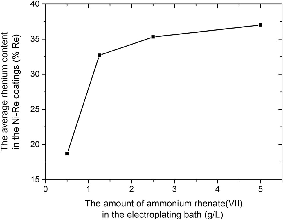
The relationship between the average rhenium content in the Ni–Re coatings and the amount of ammonium rhenate(vii) in the electroplating bath.
The research on the morphology of Ni–Re coatings showed that the layers are highly textured and the surface is homogeneous with a clearly marked islet character. The coating with the highest content of rhenium (Ni–37Re) was additionally subjected to EDS analysis (Figure 2). These investigations confirmed that rhenium and nickel are present on the coating surface. The maximum discrepancy in the rhenium content at the examined points on the surface was 2.8%. The calculated average of the tested three points was 37.02% (Table 1). Thus, it coincides with the value obtained in the tests by the XRF method.
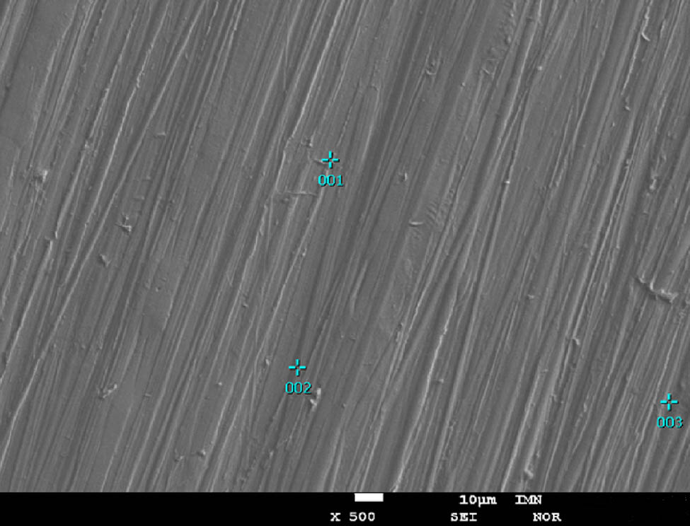
Surface morphology of the Ni–37Re coating (j = 25 mA·cm−2, 5 g·L−1 of ammonium rhenate(vii) in the bath) with the three points of EDS analysis.
Chemical composition of the Ni–37Re coating (j = 25 mA·cm−2, 5 g·L−1 of ammonium rhenate(vii) in the bath of the alloy coating) in the three different points
| Point number | Element | Mass (%) | Atom (%) | Sigma | Net | Ratio | Line |
|---|---|---|---|---|---|---|---|
| 001 | Ni | 61.7 | 83.66 | 0.1 | 165,912 | 0.725101 | K |
| Re | 38.26 | 16.34 | 0.14 | 248,406 | 0.265955 | M | |
| 002 | Ni | 64.18 | 85.58 | 0.1 | 5,656,342 | 0.794836 | K |
| Re | 35.82 | 14.42 | 0.1 | 7,648,606 | 0.23373 | M | |
| 003 | Ni | 63.02 | 84.39 | 0.09 | 137,145 | 0.592663 | K |
| Re | 36.98 | 15.61 | 0.14 | 350,274 | 0.370817 | M |
Figure 3 shows the cross-section of the Ni–37Re coating with the maps of the distribution of elements. On the element distribution maps, the changes in the concentration reflect the colors from red – maximum concentration, through yellow, green, blue to black – minimum content. When analyzing the obtained image, it should be stated that the tested material is characterized by high homogeneity over the entire cross-section of the coating. The obtained maps of the elemental distribution confirm the uniform distribution of the elements in the coating.
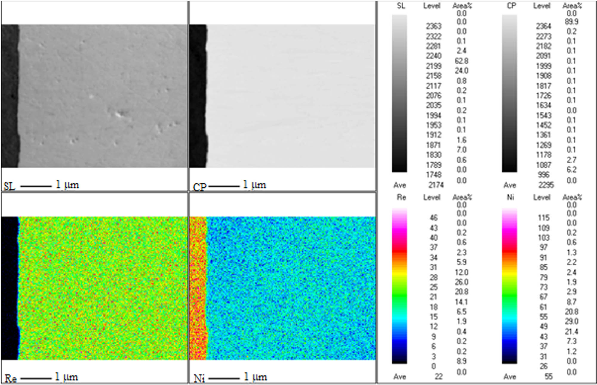
Cross-section of the Ni–37Re coating (j = 25 mA·cm−2, 5 g·L−1 of ammonium rhenate(vii) in the bath).
XRD data used for the analysis of the structure and phase properties of coatings and substrate are shown in Figure 4 and only the Ni phase in the substrate is observed. In contrast, the diffractogram from the coating showed three peaks with a broadened profile. The presence of X-ray “amorphous hallo,” characteristic for phases with the amorphous structure, was not observed. The observed broadening of the diffraction peaks indicates the nanocrystalline nature of the coating. In addition, abnormalities in the occurrence of diffraction peaks and their intensities were found. This may indicate the presence of a preferential orientation in the coating, which results in distorted proportions of diffraction peaks and extinction of some reflections.
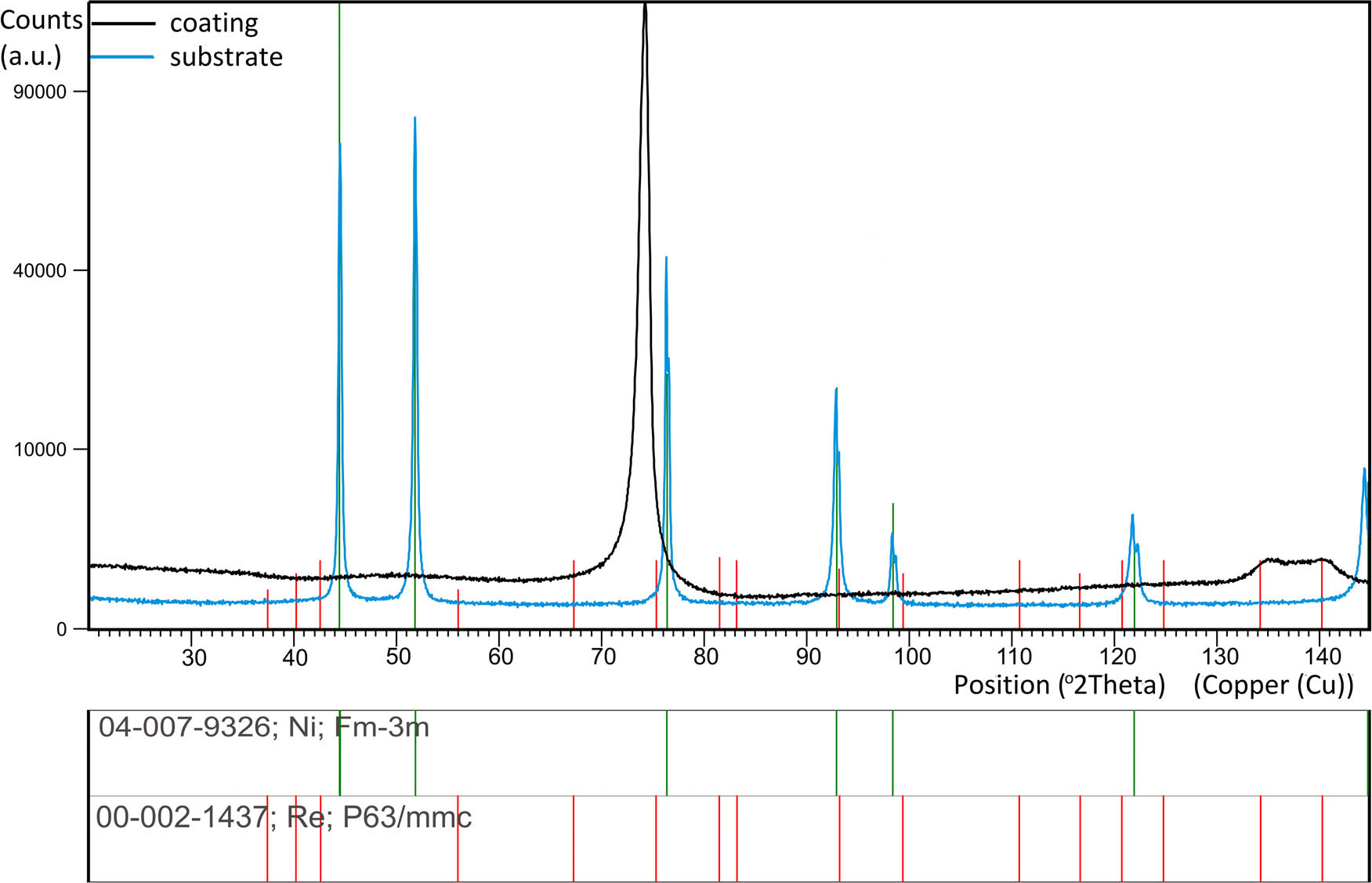
X-ray diffraction pattern of the Ni–37Re coating (j = 25 mA·cm−2, 5 g·L−1 of ammonium rhenate(vii) in the bath) and substrate.
Based on the above, the qualitative phase analysis of the coating did not clearly show the phase type. This is due to the fact that in the ICDD databases there are no files for different concentrations of elements from the Ni–Re system. Based on the chemical composition, it is most likely a solid solution of Ni(Re), which would be confirmed by the occurrence of peak 220 for the fcc Ni at an angle of 74 degrees 2Ѳ. It is significant that this peak is shifted toward lower angles, indicating the expansion of the elemental cell due to the larger atomic radius of Re (137 pm) than Ni (124 pm).
Moreover, the coating is characterized by a strong growth texture in which the {110} crystallographic planes are parallel to the substrate plane. The presence of a Re(Ni) solution cannot be ruled out as evidenced by the diffraction peaks at 135 and 140 2Ѳ angles.
The corrosion resistance of the tested coatings was assessed based on the results of electrochemical measurements in an environment of 5% NaCl solution. Open-circuit potentials of Ni–Re coatings were determined for 20 h (Figure 5).

Dependences of E = f(t) for the coatings: Ni–18.7Re (a), Ni–32.7Re (b), Ni–35.3Re (c), and Ni–37Re (d).
In the case of Ni–Re coatings, this potential practically did not change after 20 h, which proves the high stability of these alloy coatings (Figure 5). The impedance spectra recorded in the open-circuit potential are presented in the form of a Bode diagram (log ǀZǀ = f (log f)) (Figure 6), where Z is the value of impedance and f is the frequency. The behavior of the obtained coatings could be described by the one-CPE (constant phase element) electrode model (Figure 7), as was shown in ref. [5] and references therein. This model consists of the solution resistance R s in series with a parallel connection of the CPE element (Z CPE = 1/[(jω) ϕ T], where T is the capacitive parameter, ϕ is a dimensionless parameter, and ω is the angular frequency of the ac voltage) and R p is the polarization resistance [5]. Such an equivalent electrical circuit simulates the behavior of the tested material in a corrosive environment and allows the determination of circuit parameters such as R p, T, ϕ, and R s [5] (Table 2). The obtained values of the equivalent circuit parameters of coatings prove the differences in the characteristics of the interfacial boundary: Ni–Re coating | NaCl solution. Based on the obtained results, it was found that the corrosion resistance of Ni–Re coatings increases with the increase of the rhenium content in the coating. This is evidenced by increasing the polarization resistance, R p (Table 2). Higher values of this parameter suggest stronger protective properties of the coating, while lower values of this parameter indicate that a material is more susceptible to corrosion. In Ni–Re alloy coatings containing more than 35% Re, the values of polarization resistance, R p, are similar, which may prove that 2.5 g·L−1 ammonium rhenate(vii) in the electroplating bath is enough to obtain coatings characterized by high corrosion resistance. It can also be observed that the capacitive parameter T has lower values for coatings containing more rhenium (Table 2), which confirms the effect of reducing the ability of these materials to exchange electric charge with the corrosive environment.

Dependences of log ǀZǀ = f(log f) for the coatings: Ni–18.7Re (a), Ni–32.7Re (b), Ni–35.3Re (c), and Ni–37Re (d).

Equivalent circuit scheme (R s – solution resistance, CPE – constant phase element, R p – polarization resistance).
Equivalent circuit parameters obtained on the basis of EIS data depending on the rhenium content in the Ni–Re coating
| Amount of ammonium rhenate(vii) in the electroplating bath (g·L−1) | % Re | R p (Ω·cm2) | T | ϕ | R s (Ω·cm2) |
|---|---|---|---|---|---|
| 0.5 | 18.7 | 9,010 | 0.00049 | 0.67 | 0.35 |
| 1.25 | 32.7 | 9,714 | 0.00031 | 0.68 | 0.37 |
| 2.5 | 35.3 | 10,755 | 0.00020 | 0.67 | 0.32 |
| 5.0 | 37 | 10,931 | 0.00017 | 0.68 | 0.31 |
In order to additionally analyze the obtained data, the value of the impedance modulus for a frequency of 0.1 Hz was determined. The magnitude of the low-frequency impedance modulus is often used as a simple index to compare coatings [32]. The greater the value of Z, the better the corrosion resistance of the material. The log |Z|0.1 value increases with increasing rhenium content from 3.40 to 3.75 in the coating (Table 3) (Figure 6). In the case of the Ni–37Re coating containing the most rhenium, the highest value of log |Z|0.1 was recorded. In general, in the whole range of tested frequencies, values of the log |Z| parameter are much higher for the Ni–37Re coating, which corresponds to more effective corrosion resistance than Ni–Re coatings containing less rhenium (Figure 6).
Corrosion resistance parameters obtained by the EIS method, depending on the rhenium content in the Ni–Re coating
| Amount of ammonium rhenate(vii) in the electroplating bath (g·L−1) | % Re | log |Z|0.1 | C dl (F·cm−2) | R f |
|---|---|---|---|---|
| 0.5 | 18.7 | 3.40 | 0.000888 | 44.40 |
| 1.25 | 32.7 | 3.56 | 0.000285 | 14.26 |
| 2.5 | 35.3 | 3.69 | 0.000006 | 0.31 |
| 5.0 | 37 | 3.75 | 0.000004 | 0.17 |
On the basis of the obtained equivalent circuit parameters, the double-layer capacitance, C dl, was calculated according to equation (1) and then the value of the factor of electrochemically active surface area, R f, was calculated according to equation (2) [5] (Table 3):
The value of R f (the ratio of capacitances C dl determined for the Ni–Re coating and for the ideally smooth nickel electrode, according to the above equation) for the Ni–37Re coating is about 260 times lower than that for the Ni–18.7Re coating, indicating the more efficient blocking of the corrosion process (Table 3). Higher values of this parameter indicate a larger interfacial surface and thus a deterioration of the corrosion resistance of the material. It is clearly shown that the Ni–37Re coating exhibits the best anticorrosion properties in a 5% NaCl solution compared with the other coatings. This is indicated by all corrosion resistance parameters obtained. The probable cause of the improvement in the corrosion resistance of this coating is the highest content of rhenium among all the tested coatings.
The coating with the best corrosion resistance (Ni–37Re) was subjected to further investigations. The Ni–37Re alloy coating density tests were carried out in a helium atmosphere. The density of the tested material was 11.54 g·cm−3 (Table 4). For comparison, the densities of Ni and Re are, respectively, 8.91 and 21.0 g·cm−3. The measurement of the specific surface area of the Ni–37Re coating consisted of measuring the gas (nitrogen) adsorption on the adsorbate surface. The multipoint specific surface area of Ni–37Re coating determined by the BET method (Brunauer–Emmett–Teller) was 0.2597 m2·g−1 (Table 4). The electrical conductivity of the Ni–37Re alloy coating was found to be 0.8 MS·m−1 (Table 4).
Physical properties of the Ni–37Re alloy coating
| Parameter | Value |
|---|---|
| Density (g·cm−3) (powder) | 11.54 |
| Specific surface area (m2·g−1) (powder) | 0.2597 |
| Average hardness (HV1) | 629.5 |
| Electrical conductivity (MS·m−1) | 0.8 |
| Melting point (°C) | ≤1,540 |
When analyzing the obtained parameters, it should be stated that the galvanic method allows obtaining a coating with physical properties that make it possible to recommend this material for use as a protective coating.
The results of the Vickers hardness measurements are presented in Table 5. The hardness of the electrolytic Ni–37Re coating ranged from 570 to 676 HV1, while the average of all measurements was 629.5 HV1 (Table 4). The determined values confirm the significant mechanical resistance of the obtained Ni–37Re alloy coating.
The hardness of the electrolytic Ni–37Re alloy coating measured at various points on the surface (A, E – edge, C – center, B, D – points between the edge and the center)
| Area | A | B | C | D | E |
|---|---|---|---|---|---|
| Hardness (HV1) | 636.9 | 570.6 | 610.8 | 676.3 | 653.1 |
Another parameter determining the properties of the tested material (Ni–37Re) was the melting point (Figure 8). The melting point of the tested Ni–37Re electrolytic alloy was approx. 1,540°C. Comparatively, for Ni it was about 1,453°C and that for Re was about 3,185°C. The melting point of the material constituting the alloy coating allowed for its thermal treatment, which is very difficult concerning the rhenium itself.
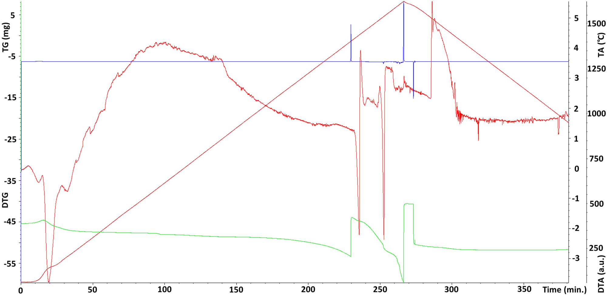
Differential thermal analysis of the Ni–37Re coating; brown line – (TA) temperature change over time in °C; red line – (DTA) differential thermal analysis temperature difference between the tested material sample and the reference material; green line – (TG) change of sample mass; blue line – (DTG) mass change rate).
During the tests, it was also found that the sample behaves very evenly during both the heating and cooling processes. This confirms the high homogeneity of the tested material. Moreover, the application of temperature changes every 6°C allowed one to record the endothermic effect accompanying the process of melting of the investigated material and the exothermic effect occurring during its solidification (Figure 8).
4 Conclusions
Based on the research, the following conclusions were drawn:
The Ni–Re coatings were found to be highly homogeneous. The broadening of the diffraction peaks suggested the nanocrystalline nature of the obtained coatings.
The conducted research found that the electrolytic Ni–Re alloy coatings are materials with high corrosion resistance. This is confirmed by the obtained corrosion resistance parameters. This is due to rhenium properties, which form a superalloy material with nickel. An additional advantage of these coatings is that even a small amount of ammonium rhenate(vii) in the electroplating bath allows one to obtain coatings with high anticorrosion parameters.
Moreover, it was found that the physical properties of the obtained alloy coating, such as hardness and melting point, recommend this material for practical use as protective coatings.
-
Funding information: This work was performed with funding from the National Centre for Research and Development and KGHM Polska Miedź in Poland with the research grant RE-COVER No CuBR/II/4/NCBR/2015.
-
Author contributions: Conceptualization, J.N. and M.P.; methodology, J.N., M.P., I.M., D.K., and A.S.S.; investigation, J.N., M.P., D.K., and I.M.; resources, J.N., M.P., and D.K.; formal analysis, J.N., M.P., D.K., I.M., and A.S.S.; writing-original draft preparation, J.N., M.P., I.M., A.S.S., and D.K.; data curation, J.N., M.P., and D.K.; writing – review and editing, J.N., M.P., I.M., A.S.S., and D.K.; visualization, M.P., and J.N. All authors have read and agreed to the published version of the manuscript.
-
Conflict of interest: The authors declare no conflict of interest.
References
[1] Golubeva, A. A., S. V. Konovalov, Y. F. Ivanov, K. A. Osintsev, and I. A. Komissarova. Layer-by-layer analysis of the Cr–Ni–Ti coating substructure obtained via selective laser melting. Journal of Surface Investigation, Vol. 14, No. 5, 2020, pp. 1022–1028.10.1134/S1027451020050286Search in Google Scholar
[2] Guzanová, A., J. Brezinová, D. Draganovská, and P. O. Maruschak. Properties of coatings created by HVOF technology using micro-and nano-sized powder. Koroze a Ochrana Materialu, Vol. 63, No. 2, 2019, pp. 86–93.10.2478/kom-2019-0011Search in Google Scholar
[3] Panin, S., I. Vlasov, D. Dudina, V. Ulyanitsky, R. Stankevich, I. Batraev, et al. Deposition of titanium based coatings by reactive detonation spraying. Koroze a Ochrana Materialu, Vol. 62, No. 1, 2018, pp. 6–13.10.2478/kom-2018-0002Search in Google Scholar
[4] Müller, T., J. Grimwood, A. Bachmaier, and R. Pippan. Electrodeposition of Fe-C alloys from citrate baths: structure, mechanical properties, and thermal stability. Metals, Vol. 8, No. 5, 2018, id. 363.10.3390/met8050363Search in Google Scholar
[5] Popczyk, M., J. Kubisztal, A. S. Swinarew, Z. Waśkiewicz, A. Stanula, and B. Knechtle. Corrosion resistance of heat-treated Ni–W alloy coatings. Materials, Vol. 13, No. 5, 2020, id. 1172.10.3390/ma13051172Search in Google Scholar PubMed PubMed Central
[6] Abdossalam, K., M. Aliofkhazraei, and F. C. Walsh. A review of electrodeposited Ni–Co alloy and composite coatings: Microstructure, properties and applications. Surface and Coatings Technology, Vol. 372, 2019, pp. 463–498.10.1016/j.surfcoat.2019.04.079Search in Google Scholar
[7] Shakoor, R. A., U. S. Waware, K. Ali, R. Kahraman, A. Popelka, M. M. Yusuf, et al. Novel electrodeposited Ni–B/Y2O3 composite coatings with improved properties. Coatings, Vol. 7, No. 10, 2017, id. 161.10.3390/coatings7100161Search in Google Scholar
[8] Wykpis, K., M. Popczyk, J. Niedbała, B. Bierska-Piech, A. Budniok, and E. Łągiewka. Influence of thermal treatment on the corrosion resistance of electrolytic Zn-Ni + Ni composite coatings. Advanced Composite Materials, Vol. 24, No. 5, 2015, pp. 431–438.10.1080/09243046.2014.901471Search in Google Scholar
[9] Popczyk, M., J. Kubisztal, and A. Budniok. Structure and electrochemical characterization of electrolytic Ni + Mo + Si composite coatings in an alkaline solution. Electrochimica Acta, Vol. 51, No. 27, 2006, pp. 6140–6144.10.1016/j.electacta.2006.01.059Search in Google Scholar
[10] Allahyarzadeh, M. H., M. Aliofkhazraei, A. R. Sabour Rouhaghdam, and V. Torabinejad. Electrodeposition of Ni–W–Al2O3 nanocomposite coating with functionally graded microstructure. Journal of Alloys and Compounds, Vol. 666, 2016, pp. 217–226.10.1016/j.jallcom.2016.01.031Search in Google Scholar
[11] Wykpis, K., M. Popczyk, J. Niedbała, A. Budniok, and E. Łągiewka. Influence of the current density of deposition on the properties of Zn-Ni coatings. Materials Science, Vol. 47, No. 6, 2012, pp. 838–847.10.1007/s11003-012-9463-4Search in Google Scholar
[12] Allahyarzadeh, M. H., M. Aliofkhazraei, A. R. Rezvanian, V. Torabinejad, and A. R. Sabour Rouhaghdam. Ni–W electrodeposited coatings: Characterization, properties and applications. Surface and Coatings Technology, Vol. 37, 2016, pp. 978–1010.10.1016/j.surfcoat.2016.09.052Search in Google Scholar
[13] Wykpis, K., M. Popczyk, J. Niedbała, A. Budniok, E. Łągiewka, and B. Bierska-Piech. Influence of thermal treatment on the corrosion resistance of electrolytic Zn–Ni coatings. Materials Science-Poland, Vol. 29, No. 3, 2012, pp. 177–183.10.2478/s13536-011-0028-2Search in Google Scholar
[14] Popczyk, M., A. Budniok, and E. Łągiewka. Structure and corrosion resistance of nickel coatings containing tungsten and silicon powders. Materials Characterization, Vol. 58, No. 4, 2007, pp. 371–375.10.1016/j.matchar.2006.06.002Search in Google Scholar
[15] Wykpis, K., J. Niedbała, M. Popczyk, A. Budniok, and E. Łągiewka. The electrodeposition and properties of Zn-Ni + Ni composite coatings. Russian Journal of Electrochemistry, Vol. 48, No. 11, 2012, pp. 1123–1129.10.1134/S1023193512080149Search in Google Scholar
[16] Popczyk, M. The influence of molybdenum and silicon on activity of Ni + W composite coatings in the hydrogen evolution reaction. Surface and Interface Analysis, Vol. 40, No. 3–4, 2008, pp. 246–249.10.1002/sia.2696Search in Google Scholar
[17] Wykpis, K., M. Popczyk, and A. Budniok. Electrolytic deposition and corrosion resistance of Zn-Ni coatings obtained from sulphate-chloride bath. Bulletin of Materials Science, Vol. 34, No. 4, 2011, pp. 997–1001.10.1007/s12034-011-0228-8Search in Google Scholar
[18] Popczyk, M. The hydrogen evolution reaction on electrolytic nickel-based coatings containing metallic molybdenum. Materials Science Forum, Vol. 636–637, 2010, pp. 1036–1041.10.4028/www.scientific.net/MSF.636-637.1036Search in Google Scholar
[19] Xu, Y., T. Hirano, H. Kunieda, Y. Hara, and Y. Miyata. Enhancing the methane steam reforming catalytic performance of Ni monolithic catalysts via Ni–Re surface alloying. The Royal Society of Chemistry, Catalysis Science & Technology, Vol. 10, 2020, pp. 2004–2019.10.1039/C9CY02539ASearch in Google Scholar
[20] Neikov, O. D., S. S. Naboychenko, and N. A. Yefimov. Production of refractory metal powders. Handbook of non-ferrous metal powders. Second edition, Elsevier, 2018, p. 995.10.1016/B978-0-08-100543-9.00023-3Search in Google Scholar
[21] Murugan, S. and P. K. Chaurasia. In-reactor creep testing: techniques. Reference module in materials science and materials engineering, Elsevier, 2016.10.1016/B978-0-12-803581-8.03465-2Search in Google Scholar
[22] Briant, C. L. and M. K. Banerjee. Refractory metals and alloys. Reference module in materials science and materials engineering, Elsevier, 2016.10.1016/B978-0-12-803581-8.02584-4Search in Google Scholar
[23] Wojewoda-Budka, J., A. Wierzbicka-Miernik, L. Litynska-Dobrzynska, M. J. Szczerba, G. Mordarski, M. Mosiałek, et al. Microstructure characteristics and phase transformations of the Ni–P and Ni–P–Re electroless deposited coatings after heat treatment. Electrochimica Acta, Vol. 209, 2016, pp. 183–191.10.1016/j.electacta.2016.05.043Search in Google Scholar
[24] Kuznetsov, V. V., D. Yu, V. V. Gamburg, R. S. Zhulikov Batalov, and E. A. Filatova. Re-Ni cathodes obtained by electrodeposition as a promising electrode material for hydrogen evolution reaction in alkaline solutions. Electrochimica Acta, Vol. 317, 2019, pp. 358–366.10.1016/j.electacta.2019.05.156Search in Google Scholar
[25] Rosen, B., E. Gileadi, and N. Eliaz. Microstructure and composition of pulse plated Re–Ni alloys, on a rotating cylinder electrode. Journal of Electroanalytical Chemistry, Vol. 731, 2014, pp. 93–99.10.1016/j.jelechem.2014.08.016Search in Google Scholar
[26] Naor, A., N. Eliaz, and E. Gileadi. Electrodeposition of rhenium–nickel alloys from aqueous solutions. Electrochimica Acta, Vol. 54, No. 25, 2009, pp. 6028–6035.10.1016/j.electacta.2009.03.003Search in Google Scholar
[27] Naor, A., N. Eliaz, E. Gileadi, and S. R. Taylor. Properties and applications of rhenium and its alloys. The AMMTIAC Quarterly, Vol. 5, No. 1, 2013, pp. 11–15.Search in Google Scholar
[28] Wen, S. The electrodeposition and property study of nickel–rhenium alloy. Master’s thesis. Louisiana State University, 3063, 2005.Search in Google Scholar
[29] Davydov, A., V. Shaldaev, A. Malofeeva, O. Chernyshova, and V. Volgin. Determination of corrosion rate of rhenium and its alloys. Chemical Engineering Transactions, Vol. 41, 2014, pp. 289–294.Search in Google Scholar
[30] Yapontseva, Y., T. Maltseva, and V. Kublanovsky. Electrosynthesis of nanostructured thin coatings with superalloys CoW, CoRe and CoWRe with valuable properties in hardness and corrosion resistance. Materials Today: Proceedings, November 26, 2019.10.1016/j.matpr.2019.11.115Search in Google Scholar
[31] Yapontseva, Yu S., T. V. Maltseva, V. S. Kublanovsky, O. A. Vyshnevskyi, and Yu N. Troshchenkov. Electrodeposition and properties of Co–Re alloys. The International Journal of Refractory Metals and Hard Materials, Vol. 96, 2021, id. 105469.10.1016/j.ijrmhm.2021.105469Search in Google Scholar
[32] Hinderliter, B. R., S. G. Croll, D. E. Tallman, Q. Su, and G. P. Bierwagen. Interpretation of EIS data from accelerated exposure of coated metals based on modeling of coating physical properties. Electrochimica Acta, Vol. 51, No. 21, 2006, pp. 4505–4515.10.1016/j.electacta.2005.12.047Search in Google Scholar
© 2021 Jolanta Niedbała et al., published by De Gruyter
This work is licensed under the Creative Commons Attribution 4.0 International License.
Articles in the same Issue
- Review Articles
- A review on filler materials for brazing of carbon-carbon composites
- Nanotechnology-based materials as emerging trends for dental applications
- A review on allotropes of carbon and natural filler-reinforced thermomechanical properties of upgraded epoxy hybrid composite
- High-temperature tribological properties of diamond-like carbon films: A review
- A review of current physical techniques for dispersion of cellulose nanomaterials in polymer matrices
- Review on structural damage rehabilitation and performance assessment of asphalt pavements
- Recent development in graphene-reinforced aluminium matrix composite: A review
- Mechanical behaviour of precast prestressed reinforced concrete beam–column joints in elevated station platforms subjected to vertical cyclic loading
- Effect of polythiophene thickness on hybrid sensor sensitivity
- Investigation on the relationship between CT numbers and marble failure under different confining pressures
- Finite element analysis on the bond behavior of steel bar in salt–frost-damaged recycled coarse aggregate concrete
- From passive to active sorting in microfluidics: A review
- Research Articles
- Revealing grain coarsening and detwinning in bimodal Cu under tension
- Mesoporous silica nanoparticles functionalized with folic acid for targeted release Cis-Pt to glioblastoma cells
- Magnetic behavior of Fe-doped of multicomponent bismuth niobate pyrochlore
- Study of surfaces, produced with the use of granite and titanium, for applications with solar thermal collectors
- Magnetic moment centers in titanium dioxide photocatalysts loaded on reduced graphene oxide flakes
- Mechanical model and contact properties of double row slewing ball bearing for wind turbine
- Sandwich panel with in-plane honeycombs in different Poisson's ratio under low to medium impact loads
- Effects of load types and critical molar ratios on strength properties and geopolymerization mechanism
- Nanoparticles in enhancing microwave imaging and microwave Hyperthermia effect for liver cancer treatment
- FEM micromechanical modeling of nanocomposites with carbon nanotubes
- Effect of fiber breakage position on the mechanical performance of unidirectional carbon fiber/epoxy composites
- Removal of cadmium and lead from aqueous solutions using iron phosphate-modified pollen microspheres as adsorbents
- Load identification and fatigue evaluation via wind-induced attitude decoupling of railway catenary
- Residual compression property and response of honeycomb sandwich structures subjected to single and repeated quasi-static indentation
- Experimental and modeling investigations of the behaviors of syntactic foam sandwich panels with lattice webs under crushing loads
- Effect of storage time and temperature on dissolved state of cellulose in TBAH-based solvents and mechanical property of regenerated films
- Thermal analysis of postcured aramid fiber/epoxy composites
- The energy absorption behavior of novel composite sandwich structures reinforced with trapezoidal latticed webs
- Experimental study on square hollow stainless steel tube trusses with three joint types and different brace widths under vertical loads
- Thermally stimulated artificial muscles: Bio-inspired approach to reduce thermal deformation of ball screws based on inner-embedded CFRP
- Abnormal structure and properties of copper–silver bar billet by cold casting
- Dynamic characteristics of tailings dam with geotextile tubes under seismic load
- Study on impact resistance of composite rocket launcher
- Effects of TVSR process on the dimensional stability and residual stress of 7075 aluminum alloy parts
- Dynamics of a rotating hollow FGM beam in the temperature field
- Development and characterization of bioglass incorporated plasma electrolytic oxidation layer on titanium substrate for biomedical application
- Effect of laser-assisted ultrasonic vibration dressing parameters of a cubic boron nitride grinding wheel on grinding force, surface quality, and particle morphology
- Vibration characteristics analysis of composite floating rafts for marine structure based on modal superposition theory
- Trajectory planning of the nursing robot based on the center of gravity for aluminum alloy structure
- Effect of scan speed on grain and microstructural morphology for laser additive manufacturing of 304 stainless steel
- Influence of coupling effects on analytical solutions of functionally graded (FG) spherical shells of revolution
- Improving the precision of micro-EDM for blind holes in titanium alloy by fixed reference axial compensation
- Electrolytic production and characterization of nickel–rhenium alloy coatings
- DC magnetization of titania supported on reduced graphene oxide flakes
- Analytical bond behavior of cold drawn SMA crimped fibers considering embedded length and fiber wave depth
- Structural and hydrogen storage characterization of nanocrystalline magnesium synthesized by ECAP and catalyzed by different nanotube additives
- Mechanical property of octahedron Ti6Al4V fabricated by selective laser melting
- Physical analysis of TiO2 and bentonite nanocomposite as adsorbent materials
- The optimization of friction disc gear-shaping process aiming at residual stress and machining deformation
- Optimization of EI961 steel spheroidization process for subsequent use in additive manufacturing: Effect of plasma treatment on the properties of EI961 powder
- Effect of ultrasonic field on the microstructure and mechanical properties of sand-casting AlSi7Mg0.3 alloy
- Influence of different material parameters on nonlinear vibration of the cylindrical skeleton supported prestressed fabric composite membrane
- Investigations of polyamide nano-composites containing bentonite and organo-modified clays: Mechanical, thermal, structural and processing performances
- Conductive thermoplastic vulcanizates based on carbon black-filled bromo-isobutylene-isoprene rubber (BIIR)/polypropylene (PP)
- Effect of bonding time on the microstructure and mechanical properties of graphite/Cu-bonded joints
- Study on underwater vibro-acoustic characteristics of carbon/glass hybrid composite laminates
- A numerical study on the low-velocity impact behavior of the Twaron® fabric subjected to oblique impact
- Erratum
- Erratum to “Effect of PVA fiber on mechanical properties of fly ash-based geopolymer concrete”
- Topical Issue on Advances in Infrastructure or Construction Materials – Recycled Materials, Wood, and Concrete
- Structural performance of textile reinforced concrete sandwich panels under axial and transverse load
- An overview of bond behavior of recycled coarse aggregate concrete with steel bar
- Development of an innovative composite sandwich matting with GFRP facesheets and wood core
- Relationship between percolation mechanism and pore characteristics of recycled permeable bricks based on X-ray computed tomography
- Feasibility study of cement-stabilized materials using 100% mixed recycled aggregates from perspectives of mechanical properties and microstructure
- Effect of PVA fiber on mechanical properties of fly ash-based geopolymer concrete
- Research on nano-concrete-filled steel tubular columns with end plates after lateral impact
- Dynamic analysis of multilayer-reinforced concrete frame structures based on NewMark-β method
- Experimental study on mechanical properties and microstructures of steel fiber-reinforced fly ash-metakaolin geopolymer-recycled concrete
- Fractal characteristic of recycled aggregate and its influence on physical property of recycled aggregate concrete
- Properties of wood-based composites manufactured from densified beech wood in viscoelastic and plastic region of the force-deflection diagram (FDD)
- Durability of geopolymers and geopolymer concretes: A review
- Research progress on mechanical properties of geopolymer recycled aggregate concrete