Study on impact resistance of composite rocket launcher
-
Fuzhen Pang
 ,
Yao Teng
,
Yao Teng

Abstract
The transient impact load during the launch of a rocket at sea threatens the safety of the launcher and the deck structure of the launch platform. In view of the impact resistance of the offshore rocket launcher system, this paper takes the real-scale rocket launcher system as the research object and establishes the analysis model of the fiber-reinforced composite rocket launcher based on the finite element method. Then, we explore the factors of the thickness by finite element simulation method and the angle and the position of IM7 fiber-reinforced composite, which influence the impact resistance property of the rocket launcher. The results show that the fiber-reinforced composite rocket launcher can effectively reduce the impact response of the structure and improve the impact resistance of the structure. The best laying scheme is to lay four layers of IM7 fiber material on both sides of the panels of the fixed bracket and the webs of the erector, respectively, with a single layer thickness of 0.75 mm and a laying angle of [90°/∓45°/90°].
Graphical abstract

1 Introduction
As a part of the cold launch platform at sea, the rocket launcher has the functions of carrying, supporting, installing, and so on. For the cold launch of the rocket, the vibration of the launcher will cause the initial disturbance of the rocket at the outlet, and the transient impact load may also cause damage to the launcher, thus affecting the accuracy and safety of launch. Therefore, the study of the impact resistance of the cold launch ejection device is of great significance for the structural performance evaluation of the launcher and the improvement of launch accuracy. Material is one of the main parameters that affect the vibration characteristics of the launcher, but in engineering applications, using a single material as a protective structure against explosion and impact, it is difficult to reduce the damage to the structure caused by high-speed impact load and effectively attenuate the shock wave. At the same time, modern engineering applications require the development of advanced materials that provide a broad spectrum of property combinations, such as: (i) high specific strength (lightweight and high strength) and ductility for aerospace, automobile, and ship applications where fuel economy and enhanced engine performance become critical; (ii) superior wear resistance, high specific stiffness and satisfactory corrosion resistance in defense applications, and so forth [1]. By laying high-performance materials on the outer layer with metal as the inner base, such as carbon fiber and boron fiber, high-performance composites with toughness, ductility, thermal conductivity, high strength, high hardness, high modulus, and so on can be effectively realized [2,3,4]. Through the use of high-strength materials in the outer layer and the composite structure of multilayer materials with cushioning energy-absorbing materials, the purpose of anti-explosion and impact can be achieved, that is, the anti-explosion and impact effects can be achieved through the combination of rigid materials and flexible materials [5]. The combination can give full play to the advantages of monomer materials to achieve the purpose of learning from each other and enhancing the anti-explosion effect.
In terms of impact response of composite structures, Rajaneesh et al. [6] studied the high-velocity impact response of quasi-isotropic carbon fiber-reinforced polymeric laminates cured from unidirectional plies using finite element models. They used rigid steel spheres as projectiles and extended the intraply meso-model originally proposed by Ladeveze (LMT-Cachan) for the ply behavior based on continuum damage mechanics, taking ply fracture energies and in situ strengths into account. By implementing intraply and inter ply damage modes in LS Dyna, three different types of post peak degradation strategies are compared: (a) damage rate bound model, and smeared-crack formulation-based (b) linear and (c) exponential softening laws.
Dhari [7] reported the response of composite laminates under high-velocity impact by fragments. They developed a numerical model to simulate a hostile scenario of impact of fragments after their interaction with a blast wave to study the response of cross-ply laminates. The performance of laminates is discussed based on different combinations of standoff distances and angles for deformable AA7075 and rigid Steel projectiles. The damage model is based on a combined elastic-plastic response which was found to have good agreement with existing experimental and numerical results.
Liu et al. [8,9] used a woven five-harness satin (5HS) weave with AS4 carbon fibers and unidirectional high-strength IMS60 carbon fibers to manufacture hybrid laminates, using resin infusion, to assess their performance in low-velocity impact tests. By comparing the performance of the hybrid unidirectional/woven (U/W) laminates with the pure unidirectional (PU) carbon-fiber reinforced composite laminates with equivalent layup, the hybrid laminates were shown to yield better impact resistance.
Yang et al. [10] built a 3-D finite element model to investigate the high-velocity impact response of FMLs using ABAQUS/Explicit platform; the results showed that the effect of fiber stacking sequence on the impact performance of FMLs is very limited under critical penetration velocity, and the damage pattern depends on the projectile incident angle. Yang et al. [11] also verified their mode of inter-ply hybrid composites based on woven fabrics and polymerized cyclic butylene terephthalate resin subjected to low-velocity impact.
In addition, many scholars have carried out related research. The research on vibration characteristics and impact response of composite structures mainly includes numerical method, analytical method, and experimental method [12,13,14,15,16,17,18,19,20,21]. Li et al. [22] proposed an integrated model for prediction of the dynamic behaviors involving vibration and impact on hybrid fiber-metal laminates (FMLs) embedded with a viscoelastic layer and performed the detailed experimental test. The outputs provide important references for this type of composite hybrid structures with improvement in the anti-vibration and impact resistant capabilities. Payeganeh et al. [23] presented several theoretical models of FMLs subjected to low-velocity impact excitation via an assumption of two degrees of freedom spring-mass system. Based on the 1st-order shear deformation theory, Shooshtari and Razavi [24] presented a novel vibration model of FMLs to predict the natural frequencies and transverse responses. Shariyat and Hosseini [25] established an impact model of composite sandwich plates with viscoelastic cores. However, the effects of failure modes such as delamination, tensile fracture of fiber and matrix on the impact contact forces, and energy absorption properties were not considered. To simulate the failure behavior of a composite sandwich plate subjected to impact loading, Long et al. [26] proposed a numerical model of the plate with a foam core by ignoring its fluidity. Liao and Jia [27] studied dynamic structural responses and failure mechanisms of composite pressure vessels subjected to low-velocity impact. They built a three-dimensional laminated media model to calculate the impact responses of composite pressure vessels using ABAQUS/Explicit. The outputs showed that the experimental and numerical results agreed well. Rafiee et al. [28,29], based on the layer-wise theory, developed a theoretical solution for predicting the low-velocity impact-induced failure in composite cylinders. And, the obtained results are validated with available experimental observations in open literature. Choi [30] investigated the transient response of composite laminated cylindrical shells with convex and concave shapes subjected to low-velocity impact and concluded that geometrically nonlinear analysis must be performed with consideration of the membrane effect of the curved shell, in order to accurately analyze its impact response. Zhang et al. [31] proposed a finite element model to investigate the dynamic mechanical response and damage modes in cross-ply composite laminates under transverse low-velocity impact. By adopting Hashin criterion and a gradual degradation scheme, the simulation results agree well with the available experimental data. Using the proposed model, they also investigated the effect of interface friction on the delamination response of cross-ply composite laminates under impact. In the study presented by Evci et al. [32], different types of composites specimens; unidirectional E-Glass, woven E-Glass, and woven aramid composite specimens were tested under low-velocity impact. Based on experimental results, the damage growth in woven composites was constrained within a smaller area compared with unidirectional composites and shown to have superior damage resistance than unidirectional composites. Tsartsaris et al. [33] reported the low-velocity impact response of FMLs through testing and numerical simulations. Their results show that the FMLs are able to absorb energy through plastic deformation of the aluminum layer. Li et al. [34] investigated the influence of fiber type on the impact behavior of titanium-based FMLs and found that the use of a polyethylene fiber layer as a sandwiched element of FMLs improves their ballistic performance. More recently, Yao et al. [35] studied the influence of impactor shape on low-velocity impact response of FMLs, while Carrillo et al. [36] investigated the low-velocity impact behavior of thermoplastic-based FMLs under a set of impact energies. Lee et al. [37] fabricated carbon and glass FMLs and investigated their impact behavior under low-velocity impact loadings. The results indicated that the impact strength of FMLs is increased by the use of high-stiffness steel, achieving as well a significant reduction in weight.
It can be seen from the above literature that studies on composite materials are mostly focused on simple models such as composite plates. However, in applications of practical engineering, due to the influence of structural forms, connection modes, and other factors, the research on composite structures is still insufficient. In view of the complex structure of the rocket launcher at sea in this paper, both the analytical method and the experimental method have great limitations. At the same time, the finite element method has great advantages of high efficiency and high accuracy which have been verified by masses of scholars [38,39,40,41]. Thus, it uses the finite element method to deal with the vibration and impact response of composite structures. Moreover, the fiber-reinforced composite materials are of great interest [42,43,44,45,46], where the reinforcement is purposely made variable and may lead to more efficient designs [47,48,49]. By selecting the type of reinforcement structure and reinforcement materials, it is possible to create a structure with predetermined strength characteristics. Therefore, in this paper, the finite element method is used to compare and analyze the vibration characteristics and impact response of fiber-reinforced composite launchers with different laying modes, in order to provide reference for the practical engineering application of composite materials.
2 Finite element theory and modeling of impact response
2.1 Theory and formulation of finite element
The finite element code ABAQUS/Explicit performs dynamic analysis, using a Lagrangian formulation and integrating the equations of motion in time explicitly by means of central differences. The theory and formulation of it are discussed in the following.
2.1.1 Formulation of 4-nodes element
The type of element used in finite element simulation in this paper is three-dimensional shell element. The picture shows the motion state of the object b in the three-dimensional Cartesian coordinate system. Boundary

Diagram of 3D shell finite element.
The relevant physical quantities are expressed by tensors. By using the Lagrangian coordinate method [50,51,52,53,54,55], the relationship between the coordinate
Assuming that the moving object is divided into finite elements, the displacement of any point in the body can be expressed as
In the formula,
The vector space
The contribution of each unit is
superimposing each unit to get
where
where
In the formula, N is the interpolation matrix,
The acceleration vector at any point is
2.1.2 Explicit integral in ABAQUS/EXPLICIT
The explicit time integral of ABAQUS adopts the central difference method, and the motion balance equation is as follows:
In the formula,
The velocity and displacement of each element node at the moment
In the formula,
The new geometry of the object is obtained by the initial configuration plus the increment of displacement, that is,
For the nonlinear dynamic response analysis of undamped structures, the calculation time step is conditionally stable, as follows:
where
2.2 Finite element modeling of launcher structure
2.2.1 Finite element model and boundary condition
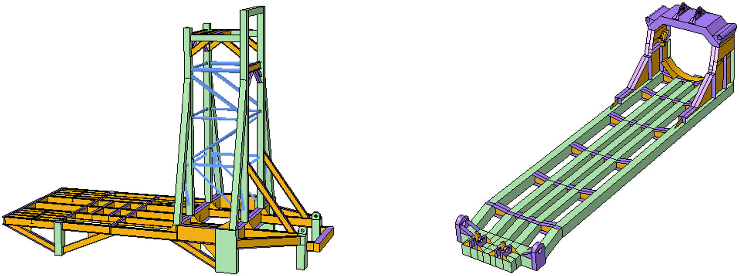
The total length of the offshore launch platform is 159.6 m, the maximum ship width is 38.8 m, and the mold depth is 10.9 m. The rocket launcher is located in the middle of the launch platform deck. When the rocket launcher is erected, it is 20.5 m long, 9 m wide, and 15.5 m high. The rocket launcher is a truss structure composed of I-beam, T-profile, box profile, and pipe profile. The main structure is composed of rocket erector and fixed bracket, which are connected by rotary shaft to provide carrier for rocket installation, testing, and launch. This paper establishes the finite element calculation model of real scale with the help of ABAQUS software. The structural model of the rocket launcher is simplified as shown in Figure 2. Compared with the strong impact load produced during rocket launch, the effect of wave load on the platform is negligible. Moreover, we only focus on the parameters of fiber-reinforced composite, which have influence on the impact resistance of rocket launcher structure. Therefore, the structural finite element model of simulation is simplified as the model shown in Figure 2(b). That is, the structural finite element model only contains the rocket launcher and its bottom cabin of the platform, and the flow field is not taken into account. The boundary condition of the cabin is set to be fixed at both ends.

Model diagram of launcher structure. (a) Structural model of offshore launch platform. (b) Finite element model of offshore launch platform and boundary condition.
As is shown in Table 1, by comparing the results of the modal analysis when the sizes of finite element are 100 mm × 100 mm, 80 mm × 80 mm, 50 mm × 50 mm, and 20 mm × 20 mm, it is found that the model has converged when the mesh size is 50 mm × 50 mm. Therefore, based on the consideration of calculation accuracy and efficiency, the finite element mesh size is chosen as 50 mm × 50 mm and the number of mesh is 354,305, and the types of the elements are S4R (Figure 3).
Results of modal analysis
| Mode | Size of element | ||||
|---|---|---|---|---|---|
| 100 mm × 100 mm | 80 mm × 80 mm | 50 mm × 50 mm | 20 mm × 20 mm | ||
| Bending | 1 | 13.723 Hz | 13.701 Hz | 13.687 Hz | 13.687 Hz |
| 2 | 33.901 Hz | 33.886 Hz | 33.882 Hz | 33.882 Hz | |
| Torsional | 1 | 27.334 Hz | 27.331 Hz | 27.329 Hz | 27.329 Hz |
| 2 | 40.265 Hz | 40.258 Hz | 40.253 Hz | 40.253 Hz | |

The modal of the erector: (a) 1st-order bending mode, (b) 2nd-order bending mode, (c) 1st-order torsional mode, and (d) 2nd-order torsional mode.
2.2.2 Material simulation and reference point
In the finite element calculation, the launcher material is made of T700 carbon fiber and steel material. The parameters and the simulation method of the materials used in this paper are referred to reference [56]. The material parameters of the model are shown in Table 2. The adhesive is used between the carbon fiber composite layer and the metal.
Fiber layer performance parameters [56]
| Material | Density
|
Elasticity E (N·m−2) | Poisson ratio
|
Yield Stress
|
|||
|---|---|---|---|---|---|---|---|
| Q235 Steel | 7.85 × 10³ | 2.06 × 10¹¹ | 0.3 | 235 | |||
| T700-Fiber layer | Density
|
E 11 (GPa) | E 22 (GPa) | µ 12 | G 12 (GPa) | G 13 (GPa) | G 23 (GPa) |
| 1,440 | 278.5 | 3.502 | 0.24 | 13.1 | 13.1 | 9 | |
The method of cold launch is adopted for launching a rocket at sea, which is similar to that of a missile. The rocket ejects out of the cylinder first and produces thrust in mid-air. The thrust of the rocket when it comes out of the cylinder is about 5 times of its own weight. In this paper, taking the offshore launcher of a certain type of rocket as an example, the mass of the rocket is about 100 t, and the impact load is simplified to a triangular shock wave load. According to the stability conditions, the stability is often 1

Loading form and position: (a) loading form and (b) loading position.
In order to compare the response of the launcher structure under this load more clearly, the reference points 1, 2, and 3 are respectively selected in the typical structural areas of the fixed bracket, the rocket erector, and the platform deck. Figure 5 shows the reference points location; point 1 is located in the middle of the side of the fixed bracket – the side near the launcher, point 2 is on the connection between the top of the rocket erector and the launcher, and point 3 is on the deck near the bottom of the launcher.

Schematic diagram of reference point selection.
3 Results and discussion
In order to explore the influence of composite materials on the impact resistance of structures, the impact response of launcher structure under the action of composite layer thickness, composite layer angle, and composite layer position is considered respectively. Taking the typical reference points of each structure as an example, the acceleration response law is analyzed.
3.1 Influence of laying thickness on impact response
It takes the scheme as an example; which four layers of fiber-reinforced materials are laid both on the top and bottom of the steel plate. The laying angle is [0°/
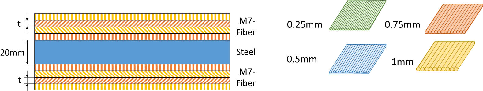
Laying mode with different laying thicknesses.
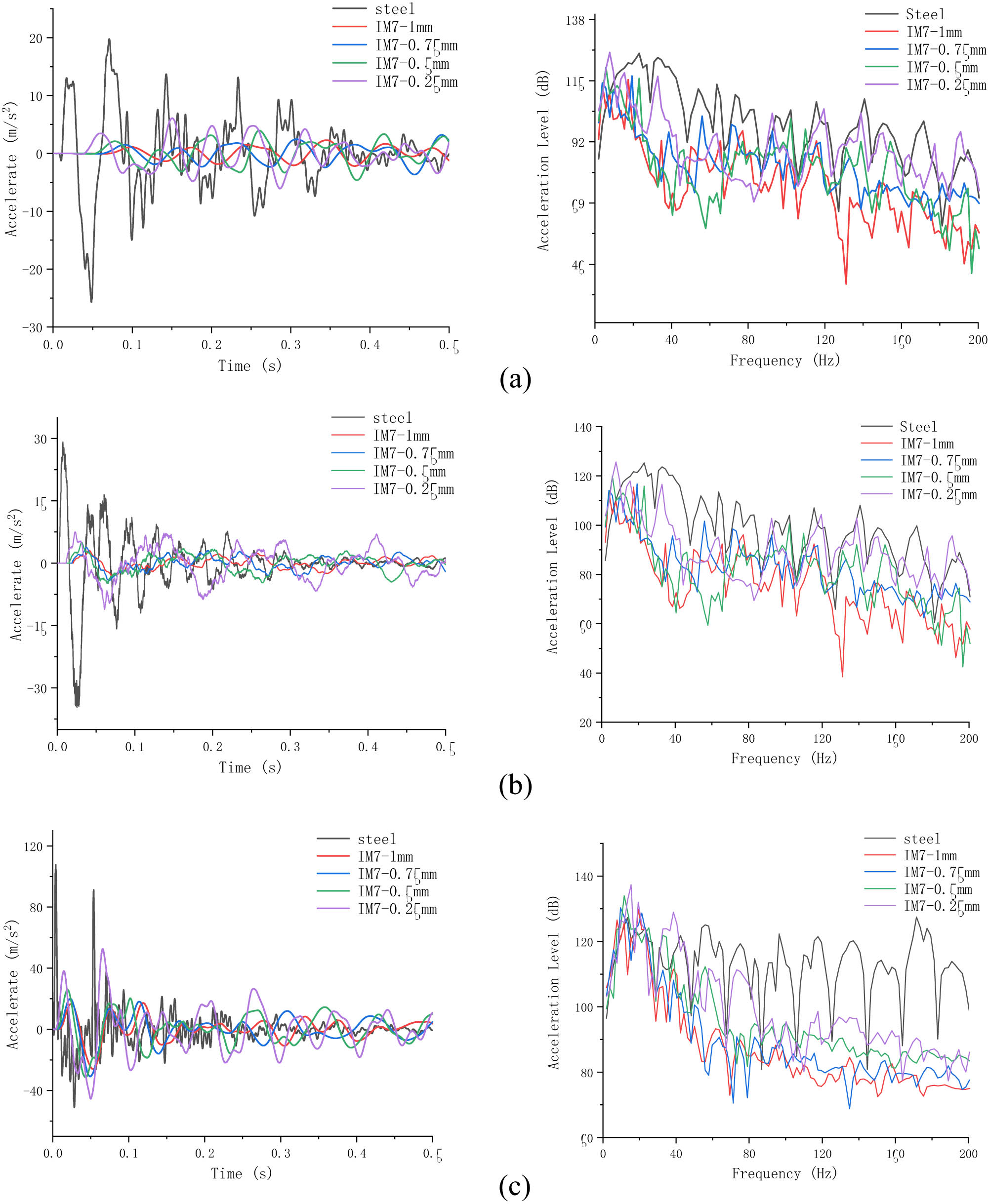
Curves of acceleration response under different laying thicknesses: (a) 1#, (b) 2#, and (c) 3#.
As can be seen from Figure 7, when subjected to impact load, the impact response law of fiber-metal sandwich composite structure is similar to that of steel structure. It shows a trend that the acceleration increases with the application of load and attenuates rapidly after the load is revoked. However, the peak value of the acceleration of the composite structure is low and so is the attenuation. The acceleration response versus time data at each reference point is transformed into the acceleration response in frequency domain by Fourier transform. It can be seen that in the frequency range of 0–200 Hz, the vibration acceleration of the composite structure at each frequency point decreases with the increase of the frequency, which is smaller than that of the steel structure as a whole. It indicates that the composite structure has a good damping effect. The vibration acceleration decreases significantly with the increase of the layer thickness when it is less than 0.75 mm, but the acceleration will not decrease any more when the layer gets thicker (Figure 8).

Diagram of acceleration response: (a) t = 0.25 mm, (b) t = 0.5 mm, (c) t = 0.75 mm, and (d) t = 1 mm.
3.2 Influence of laying angle on impact response
From the analysis of the previous section, it can be seen that when the whole structure uses fiber-reinforced composites with the same laying angle, the impact resistance of the composite launcher with 0.75 mm-thick fiber is the best. On this basis, this section further explores the influence of the laying angle of fiber-reinforced composites on the impact resistance of the structure, which are shown in Figure 9. The acceleration response of the reference point is shown in Figure 10.

Diagram of laying angles.
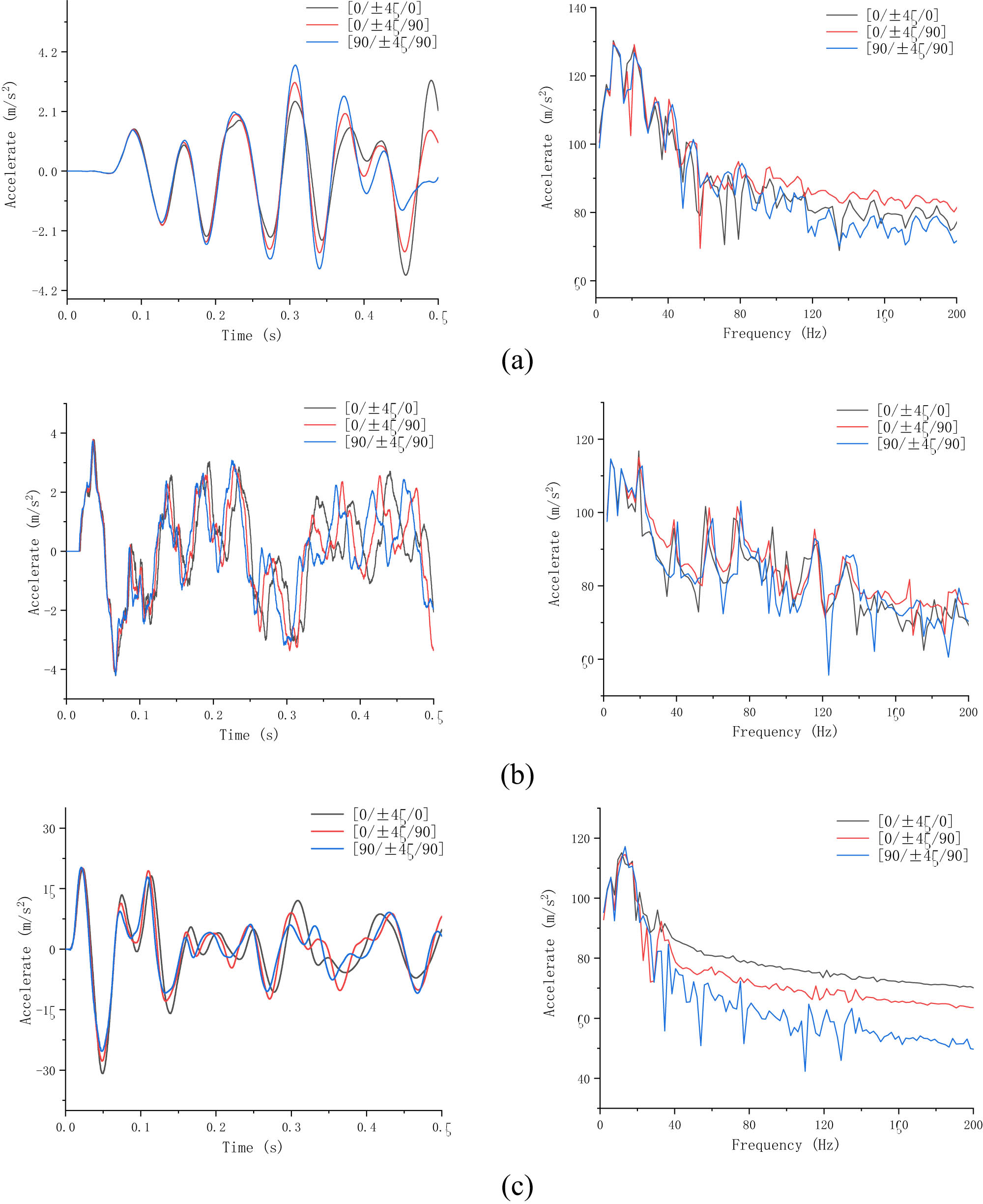
Curves of acceleration response under different laying angles: (a) 1#, (b) 2#, and (c) 3#.
As can be seen from Figure 10, when the laying angle of the fiber-reinforced composite is different, the response of the structure will change. Combined with the curve of acceleration response versus time data and in frequency domain, we can see that under each laying angle, the trend of acceleration response with time and frequency is basically the same. When the laying angle of IM7 fiber is [90°/
![Figure 11
Diagram of acceleration response: (a) [0°/
∓
\mp
45°/0°], (b) [0°/
∓
\mp
45°/90°], and (c) [90°/
∓
\mp
45°/90°].](/document/doi/10.1515/rams-2021-0045/asset/graphic/j_rams-2021-0045_fig_011.jpg)
Diagram of acceleration response: (a) [0°/
3.3 Influence of laying position on impact response
From the analysis of the previous section, it can be seen that the impact resistance of the structure is the best when the thickness of single layer is 0.75 mm and the laying angle is [90°/
Location of composite materials for launcher structure.
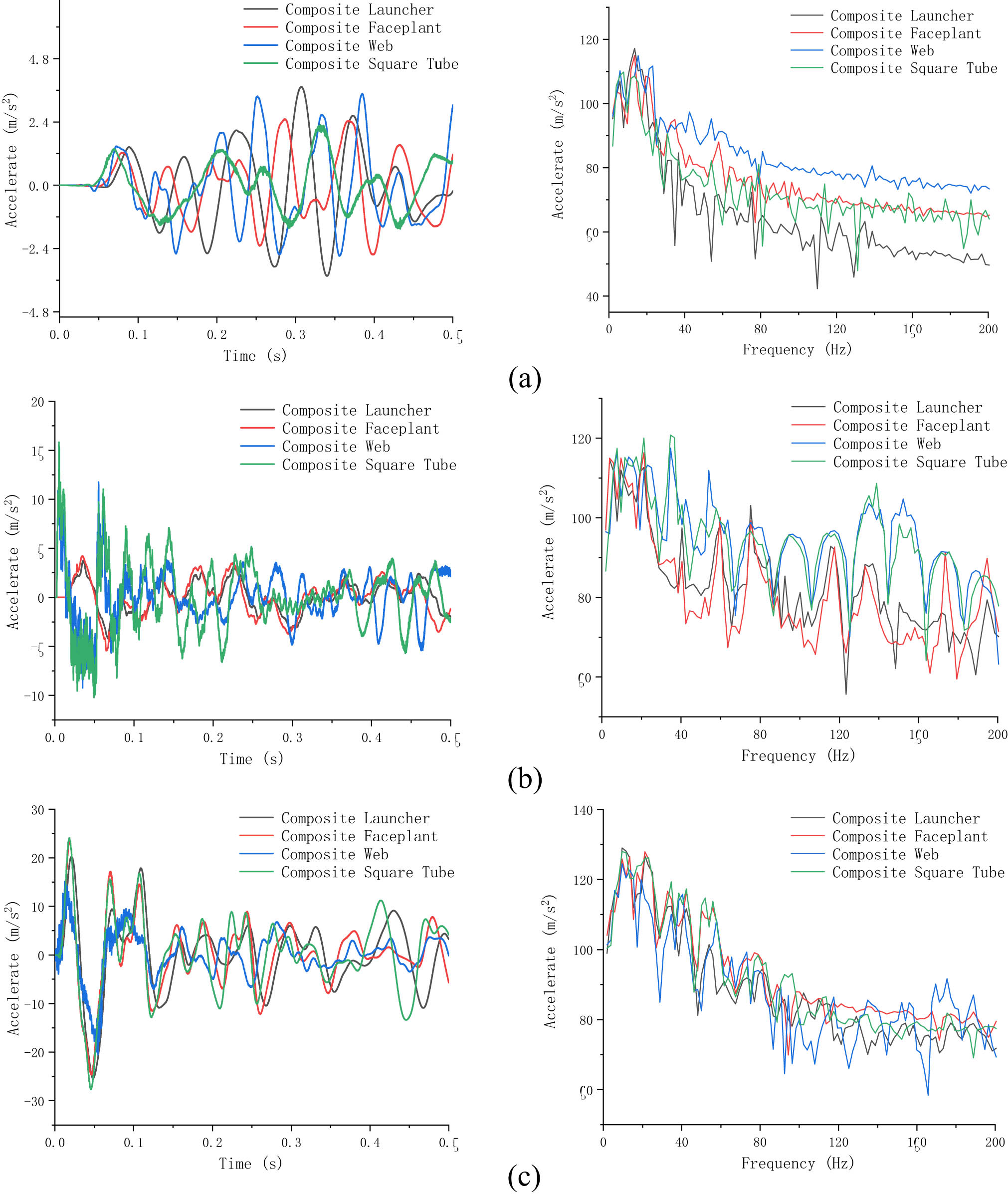
Curves of acceleration response under different laying positions: (a) 1#, (b) 2#, and (c) 3#.
As can be seen from Figure 13, when the location of the fiber-reinforced composite is different, the response of the structure is different. When the composite is applied to the whole structure of the launcher, the overall impact resistance of the launcher structure is the best. For the fixed bracket, the impact resistance of the structure with only the fiber-reinforced composite panel is close to that when the composite is used as a whole. For the rocket erector, the impact resistance property of the composite material only for the web is similar to that of the composite structure. From the curve of reference point 3, it can be seen that the acceleration response of the deck attenuates faster only when the composite is applied to the web. Therefore, considering the impact resistance and economy of the launcher structure, we can choose to lay fiber-reinforced composites in the local structure of the launcher. Combined with the simulation results of this paper, fiber-reinforced composites can be laid only on the panel of fixed bracket, the web of erector, and the web of platform deck to meet the structural safety and economic practicability (Figure 14).

Diagram of acceleration response: (a) composite launcher, (b) composite faceplate, (c) composite web, and (d) composite square tube.
4 Conclusion
In this paper, based on the finite element method, the real-scaled structural model of offshore rocket launch platform-launcher is established, and the impact responses of the structural model originally made of steel material and the structural model of fiber-reinforced composite are calculated respectively. The effects of IM7 fiber layer thickness, laying angle, and laying position on the impact response of the launcher are analyzed. The conclusions are as follows:
IM7 fiber-reinforced composites have the advantages of greater stiffness and lighter weight than steel. When they are used in rocket launchers, the structural vibration response can be effectively reduced and the impact resistance can be improved.
When the monolayer thickness of the composite is 0.75 mm, the impact resistance of the composite launcher has been significantly improved. When the monolayer thickness of the fiber-reinforced composite is less than 0.75 mm, the structural vibration response decreases with the increase of the thickness. When the monolayer thickness is greater than 0.75 mm, the vibration response decreases with the increase of the thickness.
The laying angle has an influence on the impact response of fiber-reinforced composite structures. Among the three laying methods discussed in this paper, the impact resistance of the composite rocket launcher is best with laying angle of [90°/
When the composite material is applied to the whole structure of the launcher, the overall impact resistance of the launcher structure is the best. When using composite material only for panels of the fixed bracket, the webs of the erector can meet the structural safety and economic practicability, which is the best scheme of composite lamination.
Acknowledgments
This research was supported by Harbin Engineering University, Ludong University and Yantai CIMC Raffles Offshore Ltd.
-
Funding information: This study was funded by National Natural Science Foundation of China (U2006229), National key Research and Development program (2016YFC0303406), Key Research, Development program of Shandong Province (2019JZZY010125, 2020CXGC010701, 2020CXGC010702) and Southern Marine Science and Engineering Guangdong Laboratory (Zhuhai) (311021013).
-
Author contributions: This paper was completed by six authors. Fuzhen Pang was the mentor and provide necessary guidance, Yuxuan Qin was responsible for data analysis and write the related section, Haichao Li verified and modified the paper, Qingtao Gong writed the section 1, Yao Teng and Shoujun Wang performed the simulation calculation. All the authors have proofed the paper.
-
Conflict of interest: Authors state no conflict of interest.
References
[1] Visconti, P. , P. Primiceri , R. de Fazio , L. Strafella , A. Ficarella , and A.P. Carlucci . Light-induced ignition of carbon nanotubes and energetic nano-materials: a review on methods and advanced technical solutions for nanoparticles-enriched fuels combustion. Reviews on Advanced Materials Science, Vol. 59, No. 1, 2020, pp. 26–46.10.1515/rams-2020-0010Search in Google Scholar
[2] Ahmad, S. I. , H. Hamoudi , A. Abdala , Z. K. Ghouri , and K. M. Youssef . Graphene-reinforced bulk metal matrix composites: synthesis, microstructure, and properties. Reviews on Advanced Materials Science, Vol. 59, No. 1, 2020, pp. 67–114.10.1515/rams-2020-0007Search in Google Scholar
[3] Kola, K. , M. Olejnik , and K. Olszewska . Preparation and properties of composite materials containing graphene structures and their applicability in personal protective equipment: a review. Reviews on Advanced Materials Science, Vol. 59, No. 1, 2020, pp. 215–242.10.1515/rams-2020-0025Search in Google Scholar
[4] Zhang, H. , C. Gao , H. Li , F. Pang , T. Zou , H. Wang , et al. Analysis of functionally graded carbon nanotube-reinforced composite structures: a review. Nanotechnology Reviews, Vol. 9, No. 1, 2020, pp. 1408–1426.10.1515/ntrev-2020-0110Search in Google Scholar
[5] Rajaneesh, A. , J. P. Ponthot , and M. Bruyneel . High velocity impact response of composite laminates using modified meso-scale damage models. International Journal of Impact Engineering, Vol. 147, 2020, id. 103701.10.1016/j.ijimpeng.2020.103701Search in Google Scholar
[6] Rajaneesh, A. , J. P. Ponthot , and M. Bruyneel . High velocity impact response of composite laminates using modified meso-scale damage models. International Journal of Impact Engineering, Vol. 147, 2021, id. 103701.10.1016/j.ijimpeng.2020.103701Search in Google Scholar
[7] Dhari, R. S. A numerical study on cross ply laminates subjected to stray fragments impact loading. Composite Structures, Vol. 261, 2021, id. 113563.10.1016/j.compstruct.2021.113563Search in Google Scholar
[8] Liu, H. , J. Liu , Y. Ding , J. Zheng , X. Kong , J. Zhou , et al. The behaviour of thermoplastic and thermoset carbon fibre composites subjected to low-velocity and high-velocity impact. Journal of Materials Science, Vol. 55, No. 33, 2020, pp. 15741–15768.10.1007/s10853-020-05133-0Search in Google Scholar
[9] Liu, H. , B.G. Falzon , and W. Tan . Experimental and numerical studies on the impact response of damage-tolerant hybrid unidirectional/woven carbon-fibre reinforced composite laminates. Composites Part B-Engineering, Vol. 136, 2018, pp. 101–118.10.1016/j.compositesb.2017.10.016Search in Google Scholar
[10] Yang, B. , Z. Wang , L. Zhou , J. Zhang , and W. Liang . Experimental and numerical investigation of interply hybrid composites based on woven fabrics and PCBT resin subjected to low-velocity impact. Composite Structures, Vol. 132, 2015, pp. 464–476.10.1016/j.compstruct.2015.05.069Search in Google Scholar
[11] Yang, B. , Z. Wang , L. Zhou , J. Zhang , L. Tong , and W. Liang . Study on the low-velocity impact response and CAI behavior of foam-filled sandwich panels with hybrid facesheet. Composite Structures, Vol. 132, 2015, pp. 1129–1140.10.1016/j.compstruct.2015.07.058Search in Google Scholar
[12] Yang, S. , X. Kong , H. Wu , Q. Fang , and H. Xiang . Constitutive modelling of UHPCC material under impact and blast loadings. International Journal of Impact Engineering, Vol. 153, 2021, id. 103860.10.1016/j.ijimpeng.2021.103860Search in Google Scholar
[13] Wei, Z. and X. Xu . Gradient design of bio-inspired nacre-like composites for improved impact resistance. Composites Part B-Engineering, Vol. 215, 2021, id. 108830.10.1016/j.compositesb.2021.108830Search in Google Scholar
[14] Singh, R. and S. Das . Transient response of collinear Griffith cracks in a functionally graded strip bonded between dissimilar elastic strips under shear impact loading. Composite Structures, Vol. 263, 2021, id. 113635.10.1016/j.compstruct.2021.113635Search in Google Scholar
[15] Seifoori, S. , A. M. Parrany , and S. Mirzarahmani . Impact damage detection in CFRP and GFRP curved composite laminates subjected to low-velocity impacts. Composite Structures, Vol. 261, 2021, id. 113278.10.1016/j.compstruct.2020.113278Search in Google Scholar
[16] Ramakrishnan, K. R. , S. Guérard , Z. Zhang , K. Shankar , and P. Viot . Numerical modelling of foam-core sandwich panels with nano-reinforced composite facesheets. Journal of Sandwich Structures & Materials, Vol. 23, No. 4, 2021, pp. 1166–1191.10.1177/1099636219856537Search in Google Scholar
[17] Noroozi, M. , A. Zajkani , and M. Ghadiri . Dynamic plastic impact behavior of CNTs/fiber/polymer multiscale laminated composite doubly curved shells. International Journal of Mechanical Sciences, Vol. 195, 2021, id. 106223.10.1016/j.ijmecsci.2020.106223Search in Google Scholar
[18] Luo, D. , Y. Wang , F. Wang , H. Cheng , B. Zhang , and Z. Li . Influence of cover thickness on the ballistic performance of silicon carbide subjected to large-scale tungsten projectiles. Ceramics International, Vol. 47, No. 11, 2021, pp. 15783–15791.10.1016/j.ceramint.2021.02.150Search in Google Scholar
[19] Kwon, Y. W. Analysis of laminated composite plates with fluid-structure interaction using multiscale modeling technique. Multiscale and Multidisciplinary Modeling Experiments and Design, Vol. 4, No. 1, 2021, pp. 51–63.10.1007/s41939-020-00079-xSearch in Google Scholar
[20] Huang, Z. , W. Chen , H. Hao , Z. Chen , T. M. Pham , T. T. Tran , et al. Flexural behaviour of ambient cured geopolymer concrete beams reinforced with BFRP bars under static and impact loads. Composite Structures, Vol. 261, 2021, id. 113282.10.1016/j.compstruct.2020.113282Search in Google Scholar
[21] Alonso, L. , D. Garcia-Gonzalez , C. Navarro , and S. K. García-Castillo . A non-dimensional theoretical approach to model high-velocity impact on thick woven plates. Steel and Composite Structures, Vol. 38, No. 6, 2021, pp. 717–737.Search in Google Scholar
[22] Li, H. , Z. Li , Z. Xiao , X. Wang , J. Xiong , J. Zhou , et al. Development of an integrated model for prediction of impact and vibration response of hybrid fiber metal laminates with a viscoelastic layer. International Journal of Mechanical Sciences, Vol. 3, 2021, id. 106298.10.1016/j.ijmecsci.2021.106298Search in Google Scholar
[23] Payeganeh, G. H. , F. A. Ghasemi , and K. Malekzadeh . Dynamic response of fiber–metal laminates (FMLs) subjected to low-velocity impact. Thin-Walled Structures, Vol. 48, No. 1, 2010, pp. 62–70.10.1016/j.tws.2009.07.005Search in Google Scholar
[24] Shooshtari, A. and S. Razavi . A closed form solution for linear and nonlinear free vibrations of composite and fiber metal laminated rectangular plates. Composite Structures, Vol. 92, No. 11, 2010, pp. 2663–2675.10.1016/j.compstruct.2010.04.001Search in Google Scholar
[25] Shariyat, M. and S. H. Hosseini . Eccentric impact analysis of pre-stressed composite sandwich plates with viscoelastic cores: a novel global–local theory and a refined contact law. Composite Structures, Vol. 117, No. 1, 2014, pp. 333–345.10.1016/j.compstruct.2014.07.003Search in Google Scholar
[26] Long, S. , X. Yao , H. Wang , and X. Zhang . Failure analysis and modeling of foam sandwich laminates under impact loading. Composite Structures, Vol. 197, 2018, pp. 10–20.10.1016/j.compstruct.2018.05.041Search in Google Scholar
[27] Liao, B. B. and L. Y. Jia . Finite element analysis of dynamic responses of composite pressure vessels under low velocity impact by using a three-dimensional laminated media model. Thin-Walled Structures, Vol. 129, 2018, pp. 488–501.10.1016/j.tws.2018.04.023Search in Google Scholar
[28] Rafiee, R. , H. Rashedi , and S. Rezaee . Theoretical study of failure in composite pressure vessels subjected to low-velocity impact and internal pressure. Frontiers of Structural and Civil Engineering, Vol. 14, No. 6, 2020, pp. 1349–1358.10.1007/s11709-020-0650-3Search in Google Scholar
[29] Rafiee, R. , A. Ghorbanhosseini , and S. Rezaee . Theoretical and numerical analyses of composite cylinders subjected to the low velocity impact. Composite Structures, Vol. 226, 2019, id. 111230.10.1016/j.compstruct.2019.111230Search in Google Scholar
[30] Choi, I. H. Finite element analysis of low-velocity impact response of convex and concave composite laminated shells. Composite Structures, Vol. 186, 2018, pp. 210–220.10.1016/j.compstruct.2017.11.090Search in Google Scholar
[31] Zhang, C. , E. A. Duodu , and J. Gu . Finite element modeling of damage development in cross-ply composite laminates subjected to low velocity impact. Composite Structures, Vol. 173, 2017, pp. 219–227.10.1016/j.compstruct.2017.04.017Search in Google Scholar
[32] Evci, C. and M. Gülgeç . An experimental investigation on the impact response of composite materials. International Journal of Impact Engineering, Vol. 43, 2012, pp. 40–51.10.1016/j.ijimpeng.2011.11.009Search in Google Scholar
[33] Tsartsaris, N. , M. Meo , F. Dolce , U. Polimeno , M. Guida , and F. Marulo . Low-velocity impact behavior of fiber metal laminates. Journal of Composite Materials, Vol. 45, No. 7, 2011, pp. 803–814.10.1177/0021998310376108Search in Google Scholar
[34] Li, X. , X. Zhang , Y. Guo , V. P. W. Shim , J. Yang , and G. B. Chai . Influence of fiber type on the impact response of titanium-based fiber-metal laminates. International Journal of Impact Engineering, Vol. 114, 2018, pp. 32–42.10.1016/j.ijimpeng.2017.12.011Search in Google Scholar
[35] Yao, L. , C. Wang , W. He , S. Lu , and D. Xie . Influence of impactor shape on low-velocity impact behavior of fiber metal laminates combined numerical and experimental approaches – ScienceDirect. Thin-Walled Structures, Vol. 145, 2019, id. 106399.10.1016/j.tws.2019.106399Search in Google Scholar
[36] Carrillo, J. G. , N. G. Gonzalez-Canche , E. A. Flores-Johnson , and P. Cortes . Low velocity impact response of fibre metal laminates based on aramid fibre reinforced polypropylene. Composite Structures, Vol. 220, 2019, pp. 708–716.10.1016/j.compstruct.2019.04.018Search in Google Scholar
[37] Lee, D.-W. , B.-J. Park , S.-Y. Park , C.-H. Choi , and J.-I. Song . Fabrication of high-stiffness fiber-metal laminates and study of their behavior under low-velocity impact loadings. Composite Structures, Vol. 189, 2018, pp. 61–69.10.1016/j.compstruct.2018.01.044Search in Google Scholar
[38] Atta, M. , A. A. Abd-Elhady , A. Abu-Sinna , and H. E. M. Sallam . Prediction of failure stages for double lap joints using finite element analysis and artificial neural networks. Engineering Failure Analysis, Vol. 97, 2019, pp. 242–257.10.1016/j.engfailanal.2019.01.042Search in Google Scholar
[39] El-Sisi, A. E.-D. A. , O. M. El-Husseiny , E. B. Matar , H. E. D. M. Sallam , and H. A. Salim . Field-testing and numerical simulation of vantage steel bridge. Journal of Civil Structural Health Monitoring, Vol. 10, No. 3, 2020, pp. 443–456.10.1007/s13349-020-00396-2Search in Google Scholar
[40] El-Emam, H. M. , H. A. Salim , and E. D. M. Sallam . Composite patch configuration and prestraining effect on crack tip deformation and plastic zone for inclined cracks. Journal of Composites for Construction, Vol. 20, No. 4, 2016, id. 04016002.10.1061/(ASCE)CC.1943-5614.0000655Search in Google Scholar
[41] El-Emam, H. M. , H. A. Salim , and H. E. M. Sallam . Composite patch configuration and prestress effect on SIFs for inclined cracks in steel plates. Journal of Structural Engineering, Vol. 143, No. 5, 2017, id. 04016229.10.1061/(ASCE)ST.1943-541X.0001727Search in Google Scholar
[42] Alsalama, M. M. , H. Hamoudi , A. Abdala , Z. K. Ghouri , and K. M. Youssef . Enhancement of thermoelectric properties of layered chalcogenide materials. Reviews on Advanced Materials Science, Vol. 59, No. 1, 2020, pp. 371–378.10.1515/rams-2020-0023Search in Google Scholar
[43] Hashim, H. , M. S. Salleh , and M. Z. Omar . Homogenous dispersion and interfacial bonding of carbon nanotube reinforced with aluminum matrix composite: A review. Reviews on Advanced Materials Science, Vol. 58, No. 1, 2019, pp. 295–303.10.1515/rams-2019-0035Search in Google Scholar
[44] Nakonieczny, D. S. , M. Antonowicz , and Z. Paszenda . Surface modification methods of ceramic filler in ceramic-carbon fibre composites for bioengineering applications – A systematic review. Reviews on Advanced Materials Science, Vol. 59, No. 1, 2020, pp. 586–605.10.1515/rams-2020-0024Search in Google Scholar
[45] Borovkov, A. I. , D. V. Mamchits , A. S. Nemov , and A. D. Novokshenov . Problems of modeling and optimization of variable-hardness panels and structures made of layered composites. Mechanics of Solids, Vol. 53, No. 1, 2018, pp. 93–100.10.3103/S0025654418010119Search in Google Scholar
[46] Li, H. , F. Pang , C. Gao , and R. Huo . A Jacobi-Ritz method for dynamic analysis of laminated composite shallow shells with general elastic restraints. Composite Structures, Vol. 242, 2020, id. 112091 (Prepublish).10.1016/j.compstruct.2020.112091Search in Google Scholar
[47] Bhaskar, S. , M. Kumar , and A. Patnaik . Mechanical and tribological overview of ceramic particulates reinforced aluminium alloy composites. Reviews on Advanced Materials Science, Vol. 58, No. 1, 2019, pp. 280–294.10.1515/rams-2019-0033Search in Google Scholar
[48] Ni, H. , J. Zhu , Z. Wang , H. Lv , Y. Su , and X. Zhang . A brief overview on grain growth of bulk electrodeposited nanocrystalline nickel and nickel-iron alloys. Reviews on Advanced Materials Science, Vol. 58, No. 1, 2019, pp. 98–106.10.1515/rams-2019-0011Search in Google Scholar
[49] Zhang, X. , L. Zhang , H. Liu , B. Cao , L. Liu , and W. Gong . Structure, morphology, size and application of iron phosphate. Reviews on Advanced Materials Science, Vol. 59, No. 1, 2020, pp. 538–552.10.1515/rams-2020-0039Search in Google Scholar
[50] Pang, F. , H. Chen , and D. Yuan . Vibration analysis of functionally graded porous cylindrical shell with arbitrary boundary restraints by using a semi analytical method. Composites Part B: Engineering, Vol. 164, 2019, pp. 249–264.10.1016/j.compositesb.2018.11.046Search in Google Scholar
[51] Pang, F. , H. Li , J. Cui , Y. Du , and C. Gao . Application of flügge thin shell theory to the solution of free vibration behaviors for spherical-cylindrical-spherical shell: A unified formulation. European Journal of Mechanics - A/Solids, Vol. 74, 2018, pp. 381–393.10.1016/j.euromechsol.2018.12.003Search in Google Scholar
[52] Li, H. , F. Pang , X. Miao , and Y. Li . Jacobi-Ritz method for free vibration analysis of uniform and stepped circular cylindrical shells with arbitrary boundary conditions: A unified formulation. Computers & mathematics with applications, Vol. 77, No. 2, 2019, pp. 427–440.10.1016/j.camwa.2018.09.046Search in Google Scholar
[53] Li, H. , F. Pang , X. Miao , Y. Du , and H. Tian . A semi-analytical method for vibration analysis of stepped doubly-curved shells of revolution with arbitrary boundary conditions. Thin-Walled Structures, Vol. 129, 2018, pp. 125–144.10.1016/j.tws.2018.03.026Search in Google Scholar
[54] Pang, F. , H. Li , X. Wang , X. Miao , and S. Li . A semi analytical method for the free vibration of doubly-curved shells of revolution. Computers & Mathematics with Applications, Vol. 75, No. 9, 2018, pp. 3249–3268.10.1016/j.camwa.2018.01.045Search in Google Scholar
[55] Pang, F. , H. Li , H. Chen , and Y. Shan . Free vibration analysis of combined composite laminated cylindrical and spherical shells with arbitrary boundary conditions. Mechanics of Advanced Materials and Structures, Vol. 28, No. 2, 2021, pp. 182–199.10.1080/15376494.2018.1553258Search in Google Scholar
[56] Chang, L. , Y. Guolai , F. Xuekun , and S. Quanzhao . Study on dynamic impact response of composite overwrapped gun tube. Journal of Ballistics, Vol. 32, No. 4, 2020, pp. 76–82 +96.Search in Google Scholar
© 2021 Fuzhen Pang et al., published by De Gruyter
This work is licensed under the Creative Commons Attribution 4.0 International License.
Articles in the same Issue
- Review Articles
- A review on filler materials for brazing of carbon-carbon composites
- Nanotechnology-based materials as emerging trends for dental applications
- A review on allotropes of carbon and natural filler-reinforced thermomechanical properties of upgraded epoxy hybrid composite
- High-temperature tribological properties of diamond-like carbon films: A review
- A review of current physical techniques for dispersion of cellulose nanomaterials in polymer matrices
- Review on structural damage rehabilitation and performance assessment of asphalt pavements
- Recent development in graphene-reinforced aluminium matrix composite: A review
- Mechanical behaviour of precast prestressed reinforced concrete beam–column joints in elevated station platforms subjected to vertical cyclic loading
- Effect of polythiophene thickness on hybrid sensor sensitivity
- Investigation on the relationship between CT numbers and marble failure under different confining pressures
- Finite element analysis on the bond behavior of steel bar in salt–frost-damaged recycled coarse aggregate concrete
- From passive to active sorting in microfluidics: A review
- Research Articles
- Revealing grain coarsening and detwinning in bimodal Cu under tension
- Mesoporous silica nanoparticles functionalized with folic acid for targeted release Cis-Pt to glioblastoma cells
- Magnetic behavior of Fe-doped of multicomponent bismuth niobate pyrochlore
- Study of surfaces, produced with the use of granite and titanium, for applications with solar thermal collectors
- Magnetic moment centers in titanium dioxide photocatalysts loaded on reduced graphene oxide flakes
- Mechanical model and contact properties of double row slewing ball bearing for wind turbine
- Sandwich panel with in-plane honeycombs in different Poisson's ratio under low to medium impact loads
- Effects of load types and critical molar ratios on strength properties and geopolymerization mechanism
- Nanoparticles in enhancing microwave imaging and microwave Hyperthermia effect for liver cancer treatment
- FEM micromechanical modeling of nanocomposites with carbon nanotubes
- Effect of fiber breakage position on the mechanical performance of unidirectional carbon fiber/epoxy composites
- Removal of cadmium and lead from aqueous solutions using iron phosphate-modified pollen microspheres as adsorbents
- Load identification and fatigue evaluation via wind-induced attitude decoupling of railway catenary
- Residual compression property and response of honeycomb sandwich structures subjected to single and repeated quasi-static indentation
- Experimental and modeling investigations of the behaviors of syntactic foam sandwich panels with lattice webs under crushing loads
- Effect of storage time and temperature on dissolved state of cellulose in TBAH-based solvents and mechanical property of regenerated films
- Thermal analysis of postcured aramid fiber/epoxy composites
- The energy absorption behavior of novel composite sandwich structures reinforced with trapezoidal latticed webs
- Experimental study on square hollow stainless steel tube trusses with three joint types and different brace widths under vertical loads
- Thermally stimulated artificial muscles: Bio-inspired approach to reduce thermal deformation of ball screws based on inner-embedded CFRP
- Abnormal structure and properties of copper–silver bar billet by cold casting
- Dynamic characteristics of tailings dam with geotextile tubes under seismic load
- Study on impact resistance of composite rocket launcher
- Effects of TVSR process on the dimensional stability and residual stress of 7075 aluminum alloy parts
- Dynamics of a rotating hollow FGM beam in the temperature field
- Development and characterization of bioglass incorporated plasma electrolytic oxidation layer on titanium substrate for biomedical application
- Effect of laser-assisted ultrasonic vibration dressing parameters of a cubic boron nitride grinding wheel on grinding force, surface quality, and particle morphology
- Vibration characteristics analysis of composite floating rafts for marine structure based on modal superposition theory
- Trajectory planning of the nursing robot based on the center of gravity for aluminum alloy structure
- Effect of scan speed on grain and microstructural morphology for laser additive manufacturing of 304 stainless steel
- Influence of coupling effects on analytical solutions of functionally graded (FG) spherical shells of revolution
- Improving the precision of micro-EDM for blind holes in titanium alloy by fixed reference axial compensation
- Electrolytic production and characterization of nickel–rhenium alloy coatings
- DC magnetization of titania supported on reduced graphene oxide flakes
- Analytical bond behavior of cold drawn SMA crimped fibers considering embedded length and fiber wave depth
- Structural and hydrogen storage characterization of nanocrystalline magnesium synthesized by ECAP and catalyzed by different nanotube additives
- Mechanical property of octahedron Ti6Al4V fabricated by selective laser melting
- Physical analysis of TiO2 and bentonite nanocomposite as adsorbent materials
- The optimization of friction disc gear-shaping process aiming at residual stress and machining deformation
- Optimization of EI961 steel spheroidization process for subsequent use in additive manufacturing: Effect of plasma treatment on the properties of EI961 powder
- Effect of ultrasonic field on the microstructure and mechanical properties of sand-casting AlSi7Mg0.3 alloy
- Influence of different material parameters on nonlinear vibration of the cylindrical skeleton supported prestressed fabric composite membrane
- Investigations of polyamide nano-composites containing bentonite and organo-modified clays: Mechanical, thermal, structural and processing performances
- Conductive thermoplastic vulcanizates based on carbon black-filled bromo-isobutylene-isoprene rubber (BIIR)/polypropylene (PP)
- Effect of bonding time on the microstructure and mechanical properties of graphite/Cu-bonded joints
- Study on underwater vibro-acoustic characteristics of carbon/glass hybrid composite laminates
- A numerical study on the low-velocity impact behavior of the Twaron® fabric subjected to oblique impact
- Erratum
- Erratum to “Effect of PVA fiber on mechanical properties of fly ash-based geopolymer concrete”
- Topical Issue on Advances in Infrastructure or Construction Materials – Recycled Materials, Wood, and Concrete
- Structural performance of textile reinforced concrete sandwich panels under axial and transverse load
- An overview of bond behavior of recycled coarse aggregate concrete with steel bar
- Development of an innovative composite sandwich matting with GFRP facesheets and wood core
- Relationship between percolation mechanism and pore characteristics of recycled permeable bricks based on X-ray computed tomography
- Feasibility study of cement-stabilized materials using 100% mixed recycled aggregates from perspectives of mechanical properties and microstructure
- Effect of PVA fiber on mechanical properties of fly ash-based geopolymer concrete
- Research on nano-concrete-filled steel tubular columns with end plates after lateral impact
- Dynamic analysis of multilayer-reinforced concrete frame structures based on NewMark-β method
- Experimental study on mechanical properties and microstructures of steel fiber-reinforced fly ash-metakaolin geopolymer-recycled concrete
- Fractal characteristic of recycled aggregate and its influence on physical property of recycled aggregate concrete
- Properties of wood-based composites manufactured from densified beech wood in viscoelastic and plastic region of the force-deflection diagram (FDD)
- Durability of geopolymers and geopolymer concretes: A review
- Research progress on mechanical properties of geopolymer recycled aggregate concrete