Mechanical behaviour of precast prestressed reinforced concrete beam–column joints in elevated station platforms subjected to vertical cyclic loading
-


Abstract
Precast-reinforced concrete (RC) structures in urban rail transit projects can provide many advantages over their cast-in-place counterparts. However, lessons learned from past earthquakes show that beam-column joints may be a critical point of these structures and can overestimate the mechanical performance under vertical seismic loadings if not properly understood. This paper presents unbonded and bonded prestressed precast RC beam-column joints for elevated station platforms. Prestressed steel strands are used to provide joints with self-centring capacity. The performance of the proposed joints under vertical cyclic loadings is experimentally investigated and compared to that of monolithic joints in this study. The obtained results demonstrate the good properties of the proposed precast joints in terms of bearing capacity, energy dissipation capacity and ductility control. A comparison with a conventional monolithic beam-column joint indicates the better performance against earthquakes of the proposed precast prestressed joints, and the precast joint with symmetric prestressed steel strands in the top and bottom of the beam exhibits better flexural stiffness and energy dissipation capacity.
Graphical abstract

1 Introduction
At present, the mainstream urban rail transit construction method is cast-in-place in developing countries [1]. However, this construction method of elevated stations has many disadvantages [2]. For example, cast-in-place construction must set up full framing and have a large range of enclosures in the scope of the station, which will greatly impact ground traffic. In addition, environmental problems such as noise and dust during construction must be solved. Therefore, it is urgent to improve the traditional design and construction method of elevated stations and seek a safer, more efficient and more environmentally friendly construction mode [3].
Currently, precast-reinforced concrete (PC) structures are considered a more environmentally friendly alternative to conventional (cast-in-place) structures in elevated stations [3,4]. PC structures are an assembly of monolithic elements (columns, beams, slabs, etc.), i.e., PC members are fabricated in the factory, transported to the construction site, and assembled together [4]. In addition to environmental benefits, PC structures have less wet work on site and better control of component quality than cast-in-place concrete structures [5]. Furthermore, precast concrete technology can facilitate the speed of construction, which has great potential for massive urban rail projects [4].
For PC systems, connections appear to be the most critical challenge, since they play a significant role in controlling the behaviour of structures [3,4,5,6,7,8,9,10]. The performance of PC structures is greatly influenced by the connection modes. As such, precast structures often collapse due to the failure of the connection systems [2,11,12,13,14]. PC structures are distinguished from cast-in-place structures by the connection method of elements, especially by the beam–column joints [5]. Lessons learned from past earthquakes demonstrate the need for beam–column joints that are specifically conceived to make PC structures safe and permit the full exploitation of their potential [4]. There have been numerous studies on the connection mode of beam–column joints, mechanical properties of joints, and the seismic behaviour of prefabricated structures with different connection modes [3,4,5,6,15,16,17,18,19,20,21,22,23,24,25,26,27]. It is widely believed that precast prestressed beam–column joints are a promising solution to develop highly resilient seismic-resistant structural systems [4,5,28,29,30,31,32,33]. In this technology, beam–column joints are assembled by prestressed steel strands in the connections that are conceived to dissipate energy and to be easily repaired after earthquakes [28]. Yan et al. [5] also noted that the introduction of prestressing on the PC beam–column joint reduced the deformation and ensured good crack closure and deformation recovery performance of the structure.
To date, many studies have been conducted to investigate the seismic behaviour of prestressed PC beam–column joints [4,28,29,30,31,32,33,34,35,36,37,38]. Priestley and Tao [34] reported that PC beam–column joints with partially unbonded prestressing tendons had the strong self-recovery ability. The effect of energy-dissipation steel bars on the seismic performance of prestressed PC beam–column joints was experimentally investigated by Cheok et al. [35], and the self-recovering capacity was shown to be provided by the prestressing strands and energy consumed by the dissipation steel bars. To prevent concrete spalling from beam ends, Wang et al. [4] presented a type of prestressed PC beam–column joint reinforced by a steel jacket and found that it had superior resilience against earthquakes. These studies show that prestressing enhances the self-recovery ability of PC beam–column joints under seismic loadings, but some post-tensioned prestressed joints have poor energy dissipation capacity.
These studies focused on the mechanical behaviour of prestressed PC beam–column joints under horizontal seismic forces. Very limited information is available to assess the reliability of this type of joint under vertical seismic forces, which is of primary importance in strong earthquake cases such as the 1995 Hanshin Earthquake and 2008 Wenchuan Earthquake. In fact, many buildings, especially urban rail transit structures, were damaged due to the vertical earthquake shock in the 1995 Hanshin Earthquake [39], and similar cases occurred in the 2008 Wenchuan Earthquake. Moreover, the majority of previous studies focused on the application of prestressed PC joints in building structures with few elevated urban rail transit stations. The platform of an elevated station as a secondary structure may be designed as a type of frame composed of beams with large cross sections to satisfy the requirements of bearing capacity and deformation capacity under crowd loads. Hence, it does not necessarily follow the design principle of a “strong column weak beam” in the main structures. Thus, it is necessary to examine the bearing capacity and seismic response of an elevated station platform fabricated with prestressed precast technology to facilitate designers in selecting a suitable prestressed PC beam–column joint.
As mentioned earlier, the PC system has been considered a more promising alternative to cast-in-place construction, and the introduction of prestressing on the PC system can provide many advantages. It is noted that many studies on PC systems have been conducted on high-rise structures, but limited literature focused on the prestressed PC system of elevated station platforms. In addition, very limited information is available for the mechanical performance of elevated station platforms fabricated with prestressed precast technology, especially under vertical cyclic loading, which is of dominant importance in cases such as emergency evacuation (massive crowd load) and earthquake.
This study aims to develop a prestressed precast beam–column joint for elevated station platforms. For this purpose, two types of prestressed PC beam–column joints for platforms are proposed based on the prototype of an elevated station in Guangzhou city of China, which are connected by unbonded prestressed strands and dissipation steel bars and by bonded prestressed strands. This paper focuses on the mechanical behaviours of these two prestressed PC beam–column joints at elevated station platforms under vertical cyclic loadings. A series of quasi-static tests were performed on the proposed joints and a conventional cast-in-place beam–column joint. The failure mode, stiffness, bearing capacity, ductility, and energy dissipation capacity of the prestressed PC joints were analysed. The reliability of the prestressed PC joints under vertical seismic loadings was determined by comparison with the conventional cast-in-place joint.
2 Experimental programme
2.1 Design of the experimental specimens
Based on the prototype of the beam–column joint in the elevated station platform in Guangzhou city of China, as shown in Figures 1 and 2, two prestressed PC precast beam–column joints (specimens JP-UBP and JP-BP) and one monolithic beam–column joint (i.e., cast-in-place; specimen JM) were prepared and tested in the study. The letter “J” denotes the beam–column joint; the letters “P” and “M” denote the precast and monolithic casts, respectively; the letters “UBP” and “BP” denote the connection by unbonded prestressed strands and bonded prestressed strands, respectively. Each subassembly represents the beam–column joint of a plane frame extracted from a platform prototype of an elevated station. The platform structure is 1-story high with a story height of 1.6 m. Figures 1 and 2 show the schematic diagram of the elevated station and plan layout of the platform prototype, respectively. Here, the black dotted rectangle (Figure 2) indicates the position of the beam–column joint to be investigated. Only unidirectional connections are considered in this study. As shown in Figures 1 and 2, there is a π-member adjacent to the beam end in the prototype structure. To simplify the joint model, the π-member was replaced by the column adjacent to the beam end in the study, so that the beam–column joint could function as a connection. In other words, the tested joint consists of one beam and one column adjacent to the beam end, as shown in Figure 1b.

Schematic diagram: (a) elevated station and (b) simplified joint model of the platform.

Plan layout of the platform prototype.
In this study, all specimens were 1/2 scaled based on the prototype of the beam–column joint. The beam cross-section was scaled from 300 mm × 600 mm to 150 mm × 300 mm, and the column cross-section was scaled from 400 mm × 400 mm to 200 mm × 200 mm. Details of the monolithic specimen JM dimensions and rebars are shown in Figure 3. To fix the lower end of the column during the test, a concrete base was designed to connect the column end of each specimen, and it was cast as a whole with the column. Figure 4 shows the section and reinforcement of the concrete base.

Design of monolithic specimen JM (unit: mm).

Design of the concrete base (unit: mm).
The prestressed PC joint connected by unbonded prestressed strands and dissipation steel bars is called specimen JP-UBP, as demonstrated in Figure 5. Before casting, one tube and two tubes were embedded into the specimens to accommodate the post-tensioned strands and mild steel bars, respectively. The post-tensioned strands through the middle part of the precast beam and the upper part of the precast column are mainly responsible for the self-recovery capacity of PC joints. The mild steel bars are responsible for energy dissipation. To avoid local concrete failure, a 20 mm-wide grouting gap was left at the beam–column interface before the joint assembly, and the grouting gap was filled with ultra-high performance concrete (UHPC) with steel fibre. This treatment was also conducted in specimens JP-BP. Both energy-dissipation rebars had a 100 mm-long unbonded area near the beam end.

Design of specimens JP-UBP (unit: mm).
The prestressed PC joint connected by bonded prestressed strands is called specimen JP-BP, as demonstrated in Figure 6. Before casting, two tubes were embedded into the specimens to accommodate the post-tensioned strands. The post-tensioned steel strand ran through the upper and lower parts of the precast beam and connected the upper part of the precast column to form an entire joint. After the tension of the steel strands, the tube was filled with high-strength mortar, which made the steel strands bond with the concrete. The prestressed steel strands of specimen JP-BP are distinguished from those of specimen JP-UBP; the former plays a role in connection and shares the tensile stress.

Design of specimens JP-BP (unit: mm).
2.2 Material properties
The mix proportion of the commercial concrete in this study was 1 (cement):1.98 (sand):3.10 (stone):0.51 (water):0.022 (additive):0.28 (mixed material). The 60-day compressive strength and elastic modulus of the concrete cylinder with a diameter of 150 mm and a height of 300 mm were 69 MPa and 37 GPa, respectively.
Two grades of rebars were used for the specimens. Except for plain bars (HPB 300), the other reinforcements were deformed bars (HRB 400). HRB 400 steel was used as the main rebar with the diameter, yield strength, ultimate strength, and elastic modulus of 16 mm, 427, 605 MPa, and 200 GPa, respectively. Steel strands with the diameter, ultimate strength, and elastic modulus of 15.2 mm, 1,860 MPa, and 195 GPa were used as the post-tensioned steel of the specimens.
A commercial high-strength mortar was used to fill the tubes of energy dissipation steel in specimen JP-UBP and the prestressed strand in specimen JP-BP. The 7-day compressive strength and flexural strength of the mortar with 70.7 mm × 70.7 mm × 70.7 mm cubes and 40 mm × 40 mm × 160 mm prisms were 84 and 18 MPa, respectively.
The UHPC (70.7 mm × 70.7 mm × 70.7 mm cube) to grout the interface gap of JP-UBP and JP-BP had a 3-day compressive strength of 103 MPa. The mix proportions of the UHPC can be found in our previous literature [40].
Noted that the mechanical properties of the above materials were the average value of three specimens made for the same set of test parameters. The compressive strength and elastic modulus of the concrete and mortar specimens were tested under axial compression loading at room temperature. The axial compressive load, controlled by the displacement, was applied at a speed of 0.2 mm·min−1. The flexural strength of the mortar prisms was obtained by flexural test, which was controlled by the load with a speed of 50 N·s−1. The mechanical properties of rebars and steel strands were measured by the tensile test with a load speed of 6 MPa·s−1.
2.3 Assembly of the precast specimens
The cast-in-place specimen JM was cast as a whole with the concrete base. The beams and columns of the two precast specimens were individually cast, and the column was cast as a whole with the concrete base. After 28 days of curing, the connection of the beam with the column was conducted to assemble the joint specimen, as illustrated in Figure 7.
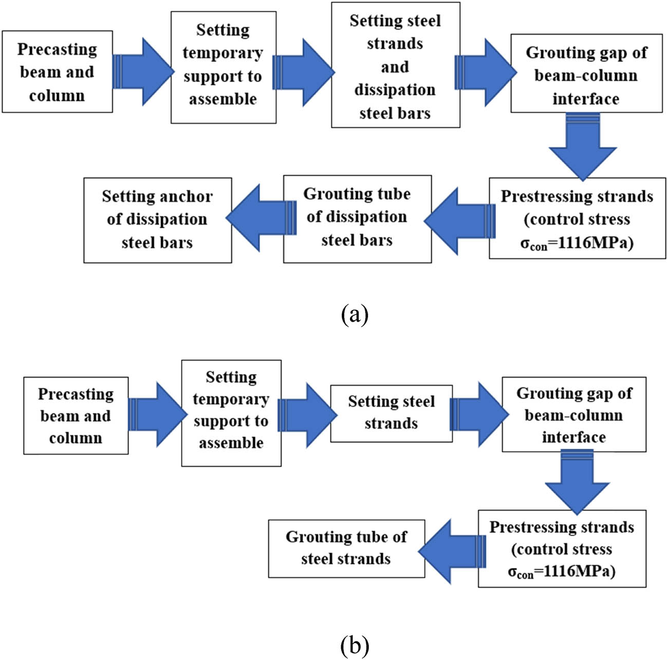
Assembly steps of precast specimens: (a) specimen JP-UBP and (b) specimen JP-BP.
2.4 Test setup
The test was conducted in the structure test hall of the Guangdong University of Technology. Figure 8 shows the typical test setup of all specimens. As shown, the concrete base connected with the column was fixed by two steel beams with four anchor bolts. The vertical cyclic loads applied on the beam end were performed by a servohydraulic machine with a 1,000 kN load cell. The reversed cyclic loads were displacement-controlled and imposed displacements with equal amplitudes but opposite signs. Figure 9 demonstrates the loading protocol, and the drift ratio is the ratio of the beam end displacement to the beam length. In the initial stage, the displacement amplitude was set to be 2.5, 5 and 10 mm for one cycle to ensure that all the specimens showed elastic responses. Subsequently, the displacement amplitude was set to be 20, 30, 40, 50, 60, 70, 80 mm, etc. for three cycles until the vertical applied load decreased to 85% of the peak load or joint was severely damaged and could not continue to resist the load.

Test setup: (a) East view and (b) West view.

Cyclic loading scheme.
The instrumentations to monitor the load, displacement and strain during the test are shown in Figure 8. The force sensors installed in the actuator were used to measure the load applied to the specimens. The time-dependent prestress force of the steel strands was monitored by fibre bragg grating (FBG) sensors, which were bonded on the midspan surface of the strands. The displacement of the specimens was recorded by linear variable differential transformers (LVDTs). Moreover, many electric resistance strain gauges were attached to the rebars of the beams and columns around the joint core and attached to the concrete surface of the beam end adjacent to the column to acquire the strain evolution of the rebars and concrete, as shown in Figure 8.
3 Experimental results and discussion
3.1 Failure modes
3.1.1 Specimen JM
During vertical cyclic loading, monolithic joint JM experienced four stages: initial crack stage, yielding stage, ultimate stage and failure stage. Figure 10 shows the distribution (front and rear views) of cracks in specimen JM under different loading displacements. At the beginning of loading, specimen JM was in the elastic stage, the load-displacement curve was linear, the displacement amplitude was basically symmetrical, and the loading and unloading curves basically coincided with each other, so there was almost no residual deformation after unloading. When the vertical displacement of the beam end was Δ = 5 mm (1/300 drift ratio), horizontal cracks first began to appear in the column and gradually developed with increasing displacement, as shown in Figure 10a. After Δ = 20 mm, the joint entered the yielding stage. At Δ = 30 mm (1/50 drift ratio), many vertical cracks appeared in the column. At Δ = 50 mm (1/30 drift ratio), the cracks in the column ran through the joint core area, and some cross-inclined cracks appeared. Then, the concrete in the column was crushed and peeled off. At Δ = 70 mm, the core area of the joint was split, and the positive bearing capacity (push-down) dropped to 65% of the peak value. At Δ = 80 mm, the positive (push-down) bearing capacity of the joint continued to decline, while the negative (pull-up) bearing capacity dropped to 95% of the peak value. The concrete in the column at the joint core area was seriously broken; thus, the test was stopped. The beam had insignificant damage during loading. The failure mode of specimen JM is shown in Figure 11. Specimen JM failed at the joint core area, which indicates that specimen JM is a typical joint with a strong beam and a weak core. This failure mode can be attributed to the beam having a larger cross section than the column, which may be required because the platform of the elevated station functions as a secondary structure. However, the failure process shows that although failure occurred in the joint core area, there was no collapse phenomenon after failure, which suggests that the bearing capacity and safety storage of specimen JM under vertical cyclic loads are not bad.

Distribution of cracks in specimen JM: (a) Δ = 5 mm; (b) Δ = 10 mm; (c) Δ = 20 mm; (d) Δ = 30 mm; (e) Δ = 40 mm; (f) Δ = 50 mm; (g) Δ = 60 mm; (h) Δ = 70 mm; and (i) Δ = 80 mm.

Failure modes of specimen JM.
3.1.2 Specimen JP-UBP
Specimen JP-UBP also experienced four stages: the initial crack stage, yielding stage, ultimate stage and failure stage, but it had a different failure process from specimen JM. Figure 12 shows the distribution (front and rear views) of cracks in specimen JP-UBP under different loading displacements. At Δ = 5 mm (1/300 drift ratio), the first horizontal crack of specimen JP-UBP appeared in the column. At Δ = 20 mm, the cracks in the column developed from the horizontal direction to the vertical direction. At Δ = 40 mm, some diagonal cracking appeared in the joint core. At Δ = 50 mm, the connection interface between beam and column opened and closed during the reserved loading. At Δ = 60 mm, the concrete in the top of the column was crushed and peeled off, and the gap at the interface between column and beam end increased during loading. At Δ = 70 mm, the steel strands significantly shrunk, accompanied by a loud noise during the second cycle of push-down loading; then, the bearing capacity of specimen JP-UBP sharply dropped. At Δ = 90 mm, the cone cracks in the joint core area continued to expand, and the concrete at the top of the column was seriously broken, which resulted in the bearing capacity of the joint dropping below 85% of the peak load. Figure 13 demonstrates the failure mode of specimen JP-UBP. As observed, the failure of specimen JP-UBP mainly occurred in the core area. Unlike the failure mode of specimen JM, the concrete at the top of the joint core area of JP-UBP exhibited local splitting failure, which could be attributed to the stress concentration caused by the local compression in the anchorage zone of prestressed strands. A comparison of Figures 11 and 13 shows that the safe storage of specimen JP-UBP after failure appears better than that of specimen JM. This finding is consistent with previous analogous investigations [4,5].

Distribution of cracks in specimen JP-UBP: (a) Δ = 5 mm; (b) Δ = 10 mm; (c) Δ = 20 mm; (d) Δ = 30 mm; (e) Δ = 40 mm; (f) Δ = 50 mm; (g) Δ = 60 mm; (h) Δ = 70 mm; and (i) Δ = 80 mm.

Failure modes of specimen JP-UBP.
3.1.3 Specimen JP-BP
The failure process of specimen JP-BP is partly similar to that of specimen JP-UBP, especially before yielding. Figure 14 shows the distribution (front and rear views) of cracks in specimen JP-BP under different loading displacements. Comparing Figures 10, 12 and 14, we observe that specimen JP-BP had the fewest cracks and smallest crack width, which indicates that specimen JP-BP had the best self-recovering capacity. Moreover, a smaller gap opened at the interface between column and beam in specimen JP-BP than in specimen JP-UBP under identical loads. Figure 15 shows the failure mode of specimen JP-BP, and the main failure occurred at the end of the column, which distinguishes it from the joint core failure of specimen JP-UBP. This result is mainly due to the arrangement of prestressed steel strands at the upper and lower parts of the joint core area, and the anchorage plate reinforced the core area, which led to better safety storage for specimen JP-BP.

Distribution of cracks in specimen JP-BP: (a) Δ = 5 mm; (b) Δ = 10 mm; (c) Δ = 20 mm; (d) Δ = 30 mm; (e) Δ = 40 mm; (f) Δ = 50 mm; (g) Δ = 60 mm; (h) Δ = 70 mm; and (i) Δ = 80 mm.

Failure modes of specimen JP-BP.
3.2 Hysteretic performance
Figure 16 illustrates the hysteretic responses of all specimens under vertical cyclic loading. In this study, the push-down displacement is defined as positive, and the corresponding load is also positive. At the initial stage of loading, the hysteresis curves were smooth and full. Although the specimen was in the elastic phase, the downward and reverse loading curves of the hysteresis loops were almost noncoincident, which is consistent with previous studies [4,5]. This result can be attributed to the geometrical asymmetry of the joints in this study. Because of the asymmetry of boundary conditions, all specimens had a fuller hysteresis curve and a higher bearing capacity under pull-up loading than under push-down loading, especially for specimen JM (two additional longitudinal reinforcements were arranged in the top compared to those in the bottom of the beam, as shown in Figure 3), as shown in Figure 16.

Hysteretic curves: (a) specimen JM; (b) specimen JP-UBP; (c) specimen JP-BP; and (d) comparison of three specimens.
With increasing loading, the hysteresis responses showed nonlinearity manifested by pinching of the hysteresis loops. Figure 16 shows that both precast specimens had fuller hysteresis loops than the monolithic specimen after yielding until the peak load. However, in the post-peak stage, specimen JP-UBP exhibited an interesting phenomenon under cyclic loading: the load increased and subsequently suddenly dropped with increasing displacement, and this phenomenon was more pronounced under push-down loading, as shown in Figure 16b). This result is attributed to the large gap at the interface between column and beam after the concrete crush, which caused a rapid drop in the hysteresis loop under large loads; however, due to the resilience of the prestressed strands, the structure can continue to bear the load until failure. Figure 16 shows that specimen JP-BP exhibited the best hysteretic performance in the post-yielding stage.
3.3 Bearing capacity and ductility
The envelope curves of the tested specimens are shown in Figure 17. Before yielding, the envelope curves of the three specimens almost coincided; in the post-peak stage, the precast specimens exhibited a significantly greater stiffness than the monolithic specimen. Thus, the advantage of the prestressing connection on the vertical load resistance mainly occurs in the post-peak stage of the beam–column joint. In addition, it is interesting to find a hardening stage of specimen JP-UBP after yielding, which may be attributed to the self-recovering capacity of the prestressed strands embedded in the middle part of the beam and the contribution of energy-dissipation rebars.

Envelope curves of specimens.
Table 1 presents the yielding load and peak load of the tested specimens. The yielding loads of the three specimens are similar, except specimen JP-BP under pull-up loading had a significantly greater yielding load than specimen JP-UBP and specimen JM, which can be due to the prestressed strands in the bottom part of the beam. Compared with specimen JM, specimen JP-UBP and specimen JP-BP improved the peak load by 16.4 and 5.4% in the push-down direction and improved the peak load by −2.1 and 6.1% in the pull-up direction. Thus, the proposed prestressed PC joints in this study have good vertical bearing capacity.
Bearing capacity and ductility of the specimens
| Specimens | Loading direction | Q y (kN) | Δy (mm) | Q p (kN) | Δp (mm) | Q u (kN) | Δu (85%) (mm) | μ | Average (μ) |
|---|---|---|---|---|---|---|---|---|---|
| JM | Push | 19.9 | 18.9 | 22.6 | 40 | 19.2 | 52.6 | 2.79 | 2.87 |
| Pull | −21.7 | −26.9 | −29.3 | −70 | −27.8a | −80a | 2.95 | ||
| JP-UBP | Push | 20.8 | 25.3 | 26.3 | 70 | 22.3 | 82.0 | 3.25 | 3.27 |
| Pull | −20.7 | −25.2 | −28.7 | −40 | −24.4 | −82.9 | 3.28 | ||
| JP-BP | Push | 18.9 | 20.0 | 23.8 | 50 | 20.2 | 73.5 | 3.68 | 3.25 |
| Pull | −26.3 | −26.7 | −30.4 | −70 | −25.8 | −75.3 | 2.82 |
Notes: Q y = yielding load; Q p = peak load; Δp = displacement at the peak load.
- a
At 95% of the post-peak load.
In this study, the ductility of beam–column joints is determined by the following equation [41,42]:
where Δ y is the yield displacement at the yielding load and Δ u is the ultimate displacement at 85% post-peak load (the ultimate displacement of specimen JM in the pull-up direction was monitored at 95% post-peak load because the test was stopped at this moment). Figure 18 shows the adopted method to define the yield displacement of all tested specimens.

Method to determine the yielding point.
The ductility comparisons of all specimens are presented in Table 1. The two precast specimens had a similar ductility, and specimen JP-UBP showed the highest ductility (μ = 3.27) among the three specimens, while the ductility of specimen JM was approximately 12% lower than that of specimen JP-UBP and specimen JP-BP. Thus, the ductility comparisons of the monolithic specimen and precast specimens show that the presented PC joints have excellent ductility under vertical cyclic loadings.
3.4 Degradation of stiffness
The stiffness of the beam–column joints is calculated as follows [18]:
where |+F i | and |−F i | are the peak loads of the ith cycle in the push and pull directions, respectively; |+X i | and |−X i | are the peak displacements of the ith cycle in the push and pull directions, respectively.
Figure 19 shows the degradation evolution of the stiffness of all specimens during cyclic loading. Because specimen JM was damaged during the preliminary preparation, it exhibited a lower stiffness before the 10 mm displacement. With displacements of 10–80 mm, the three specimens have similar stiffness curves, and the stiffness gradually decreases with increasing displacement. A comparison in Figure 19 shows that specimen JP-BP had better stiffness than specimen JP-BP and specimen JM after yielding until they reached the peak load, which is attributed to the four prestressed steel strands that were symmetrically arranged in the top and bottom of the beam.

Degradation evolution of the stiffness.
3.5 Energy dissipation capacity
The energy dissipation capacity is one of the crucial characteristics to evaluate the performances of beam–column joints under seismic loads [42]. In this study, the energy dissipation is evaluated by the enclosed area inside the hysteretic loop of each cycle [43]. The energy dissipation capacities of all specimens are shown in Figure 20. Figure 20(a) presents the energy dissipation of three specimens in each cycle. Figure 20(b) shows the accumulated energy dissipation of specimens during loadings. Figure 20(a) and (b) show that at the elastic stage (approximately Δ < 20 mm), the energy dissipation curves of the three specimens basically coincide; with the increase in joint displacement, the energy dissipation curves gradually separate; after yielding, the energy dissipation capacity of specimen JP-BP was similar to that of specimen JM but better than that of specimen JP-UBP; once entered the post-peak stage, the energy dissipation capacity of specimen JM decreased with increasing the displacement, but those of specimens JP-BP and JP-UBP continued to increase, so the accumulated energy dissipation of the two precast specimens is greater than that of the monolithic specimen. This improvement in accumulated energy dissipation of precast specimens benefited from the self-recovery capacity of the prestressed strands [4,5]. As shown in Figure 20(b), specimen JP-BP had the largest accumulated energy dissipation at failure among the three specimens; when the loading displacement was 80 mm, the accumulated energy dissipation of specimen JP-BP was higher than those of specimens JM and JP-UBP by 34 and 10%, respectively.

Energy dissipation capacity: (a) energy dissipation capacity per cycle; (b) accumulated energy dissipation; and (c) energy dissipation capacity of JP-UBP per cycle.
In addition, due to the accumulated damage under cyclic loading, the hysteresis loop area of the subsequent cycle under identical load levels is commonly lower than that of the first cycle, so the energy consumption values of three cycles with identical load levels were in a declining trend. This phenomenon can be found in the curves of specimens JM and JP-BP, as shown in Figure 20(a). However, the curve of specimen JP-UBP in Figure 20(a) did not follow this evolution. To clarify this distinguishment, Figure 20(c) presents the energy dissipation curve of specimen JP-UBP in each cycle. The energy dissipation capacity of specimen JP-UBP nonlinearly varied with the number of cycles, which could be attributed to the post-gapping (at the interface between column and beam) resilience effect of the prestressed strands embedded in the middle part of the beam. This result corresponds to the evolution of its hysteretic curve, as shown in Figure 16(b).
3.6 Displacement and rotation evolution
Figure 21(a–c) presents the evolution of the horizontal and vertical displacements of the three specimens during cyclic loading. The vertical displacement of the beam end adjacent to the column was measured by LVDT-1, and the horizontal displacement of the column end was measured by LVDT-2. As expected, these vertical and horizontal displacements of the three specimens generally increased with increasing vertical displacement of the free beam end, i.e., the loading point. Figure 21(a) shows that the horizontal displacement of the column end rapidly increased after specimen JM was yielded. This result did not occur on specimens JP-UBP and JP-BP, as shown in Figure 21(b) and (c), which can be attributed to the anchorage of prestressed strands strengthening the core area.

Displacement and rotation of specimens: (a) specimen JM; (b) specimen JP-UBP; (c) specimen JP-BP; and (d) rotation of the joint core area.
The rotation
where Δ1 and Δ2 are the displacement values measured by LVDT-2 and LVDT-3, respectively, as shown in Figure 21(d), and h is the distance between LVDT-2 and LVDT-3.
The rotation
3.7 Evolution of rebars strain and strands stress
Figure 22 shows the load-strain curves of the longitudinal reinforcement at the beam end and the stirrup in the joint core of the three specimens. The strains of the longitudinal bars of the beam end of the three specimens were relatively small, and they basically remained in the elastic stage, which was manifested by the failure mode of the specimens. Figure 22 shows that the strain of the stirrup is significantly greater than that of the beam rebar, and the stirrup of all specimens yields at failure. These findings demonstrate that great damage occurs in the joint core area of the specimens in Section 3.1. Compared with specimens JM and JP-UBP, specimens JP-BP had a lower strain in the stirrup, which indicates that the prestressed system with symmetrical arrangement can enhance the joint core, as mentioned earlier.

Rebar strain of the specimens: (a) rebar in the beam of JM; (b) rebar in the column of JM; (c) rebar in the beam of JP-UBP; (d) rebar in the column of JP-UBP; (e) rebar in the beam of JP-BP; and (f) rebar in the column of JP-BP.
Figure 23 presents the stress evolution of post-tensioned strands. As shown, specimen JP-UBP under loading had a higher strand stress variation than specimen JP-BP, but the stress variation of the prestressed strands of the two precast specimens was slight (varying below 80 MPa), which is approximately 4% of the ultimate strength of the steel strand. Thus, this strand stress variation was almost negligible and did not diminish the effect of the prestressed system. These findings reveal that the proposed joints can efficiently control the prestress loss of the post-tensioned strands under vertical cyclic loads, which is beneficial to the self-centring capacity of the joint.

Stress evolution of steel strands: (a) steel strand stress of JP-UBP vs cycles; (b) steel strand stress of JP-UBP vs displacement at the loading point; (c) upper strand’s stress of JP-BP vs cycles; (d) upper strand’s stress of JP-BP vs displacement at the loading point; (e) lower strand’s stress of JP-BP vs cycles; and (f) lower strand’s stress of JP-BP vs displacement at the loading point. (Note: the strain value was measured by the FBG sensor set on the middle of the steel strand.).
4 Conclusion
Two types of prestressed precast beam–column joints were proposed for the elevated station platform. The prestressed precast joint connected by unbonded post-tension strands embedded in the middle part of the beam and dissipation steel bars is called JP-UBP, and the prestressed precast joint connected by bonded post-tension strands symmetrically arranged in the top and bottom of the beam is called JP-BP. An experimental study was conducted to investigate the structural performance of the two precast prestressed beam–column joints under vertical cyclic loads compared to the monolithic joint. The following conclusions can be made as follows:
The monolithic joint based on the modified prototype platform exhibited a typical failure mode of a “weak joint core”. The prestress system of the precast joints could reinforce the joint core and may consequently change the failure mode.
Both precast prestressed joints have a good vertical carrying capacity. Compared with the monolithic joint, the precast prestressed joints could improve the ultimate carrying capacity by approximately 5–16% in the push-down direction.
The presented precast joints have excellent ductility under vertical cyclic loadings. The two precast specimens had similar ductility (approximately 3.2), which is approximately 12% higher than that of the monolithic joint.
Both precast prestressed joints have good energy dissipation capacity, especially after the peak load. The accumulated energy dissipation of the two precast prestressed joints is greatly higher than that of the monolithic joint at failure. Compared with JP-UBP, JP-BP has a better energy dissipation capacity under identical loads.
The precast prestressed joints have a similar stiffness degradation trend to the monolithic joint. In general, among the tested joints, JP-BP has the best stiffness before the peak load.
The two proposed joints can efficiently keep the prestress system under vertical cyclic loads and consequently provide good safety storage after peak loading.
Acknowledgements
The authors wish to acknowledge the financial support received from Guangzhou Metro Design & Research Institution Co., Ltd. The last three authors are also grateful for the financial support provided by the National Natural Science Foundation of China, the Guangdong Basic and Applied Basic Research Foundation.
-
Funding information: Guangzhou Metro Design & Research Institution Co., Ltd (No. KY-2019-064), National Natural Science Foundation of China (No.12072078), and the Guangdong Basic and Applied Basic Research Foundation (Nos. 2019B151502004).
-
Authors contributions: Haiou Shi: Conceptualization, methodology, writing – review & editing, project administration; Jinxia Zhao: conceptualization, methodology, validation, resources, writing – review & editing, funding acquisition; Fangmu Chen: Methodology, investigation, validation, writing – original draft, writing – review & editing, project administration; Junjin Lin: investigation, data curation, project administration; Jianhe Xie: methodology, data curation, writing – original draft, writing – review & editing, supervision, funding acquisition.
-
Conflict of interest: The authors declare that they have no conflict of interests or personal relationships that could have appeared to influence the work reported in this paper.
References
[1] Jh, A., B. Gqs, C. Zl, B. Bz, and D. Wz. Barriers to promoting prefabricated construction in China: A cost–benefit analysis – ScienceDirect. Journal of Cleaner Production, Vol. 172, 2018, pp. 649–660.10.1016/j.jclepro.2017.10.171Search in Google Scholar
[2] Ghayeb, H. H., H. A. Razak, and N. Sulong. Performance of dowel beam-to-column connections for precast concrete systems under seismic loads: A review – ScienceDirect. Construction Building Materials, 2020, Vol. 237, id. 117582.10.1016/j.conbuildmat.2019.117582Search in Google Scholar
[3] Zhang, Q. and M. S. Alam. State-of-the-art review of seismic resistant precast bridge columns. Journal of Bridge Engineering, Vol. 25, No. 10, 2020, id. 03120001.10.1061/(ASCE)BE.1943-5592.0001620Search in Google Scholar
[4] Wang, H., E. M. Marino, P. Pan, H. Liu, and X. Nie. Experimental study of a novel precast prestressed reinforced concrete beam-to-column joint. Engineering Structures, Vol. 156, 2018, pp. 68–81.10.1016/j.engstruct.2017.11.011Search in Google Scholar
[5] Yan, X., S. Wang, C. Huang, A. Qi, and C. Hong. Experimental study of a new precast prestressed concrete joint. Applied ences, Vol. 8, No. 10, 2018, id. 1871.10.3390/app8101871Search in Google Scholar
[6] Wu, C., J. Xie, and F. Liu. Research progress and prospects on beam-to-column connections of precast concrete fram. Concrete, Vol. 4, 2020, pp. 128–133+137 [In Chinese].Search in Google Scholar
[7] Mokhtar, R., Z. Ibrahim, M. Z. Jumaat, Z. Abd. Hamid, and A. H. Abdul Rahim. Behaviour of semi-rigid precast beam-to-column connection determined using static and reversible load tests. Measurement, Vol. 164, 2020, id. 108007.10.1016/j.measurement.2020.108007Search in Google Scholar
[8] Brunesi, E., S. Peloso, R. Pinho, and R. Nascimbene. Shake-table testing of a full-scale two-story precast wall-slab-wall structure. Earthquake Spectra, Vol. 35, No. 4, 2019, pp. 1583–1609.10.1193/072518EQS184MSearch in Google Scholar
[9] Brunesi, E., S. Peloso, R. Pinho, and R. Nascimbene. Cyclic tensile testing of a three-way panel connection for precast wall-slab-wall structures. Structural Concrete, Vol. 20, No. 4, 2019, pp. 1307–1315.10.1002/suco.201800280Search in Google Scholar
[10] Brunesi, E., R. Nascimbene, and S. Peloso. Evaluation of the Seismic Response of Precast Wall Connections: Experimental Observations and Numerical Modeling. Journal of Earthquake Engineering, Vol. 24, No. 7, 2020, pp. 1057–1082.10.1080/13632469.2018.1469440Search in Google Scholar
[11] Elsanadedy, H. M. New moment-resisting beam–column joints to increase progressive collapse resistance of precast concrete buildings. Journal of Building Engineering, Vol. 44, 2021, id. 102884.10.1016/j.jobe.2021.102884Search in Google Scholar
[12] Elsanadedy, H. M., Y. A. Al-Salloum, M. A. Alrubaidi, T. H. Almusallam, N. A. Siddiqui, and H. Abbas. Upgrading of precast RC beam–column joints using innovative FRP/steel hybrid technique for progressive collapse prevention. Construction and Building Materials, Vol. 268, 2021, id. 121130.10.1016/j.conbuildmat.2020.121130Search in Google Scholar
[13] Elsanadedy, H. M., Y. A. Al-Salloum, M. A. Alrubaidi, T. H. Almusallam, and H. Abbas. Finite element analysis for progressive collapse potential of precast concrete beam-to-column connections strengthened with steel plates. Journal of Building Engineering, Vol. 34, 2021, id. 101875.10.1016/j.jobe.2020.101875Search in Google Scholar
[14] Quiel, S. E., C. J. Naito, and C. T. Fallon. A non-emulative moment connection for progressive collapse resistance in precast concrete building frames. Engineering Structures, Vol. 179, 2019, pp. 174–188.10.1016/j.engstruct.2018.10.027Search in Google Scholar
[15] Aninthaneni, P. K., R. P. Dhakal, J. Marshall, and J. Bothara. Nonlinear cyclic behaviour of precast concrete frame sub-assemblies with “dry” end plate connection. Structures, Vol. 14, 2018, pp. 124–136.10.1016/j.istruc.2018.03.003Search in Google Scholar
[16] Shufeng, L., L. Qingning, Z. Hao, J. Haotian, Y. Lei, and J. Weishan. Experimental study of a fabricated confined concrete beam-to-column connection with end-plates. Construction Building Materials, Vol. 158, 2018, pp. 208–216.10.1016/j.conbuildmat.2017.10.025Search in Google Scholar
[17] Ketiyot, R. and C. Hansapinyo. Seismic performance of interior precast concrete beam–column connections with T-section steel inserts under cyclic loading. Earthquake Engineering and Engineering Vibration, Vol. 17, 2018, pp. 355–369.10.1007/s11803-018-0446-9Search in Google Scholar
[18] Cai, X., N. N. Gong, C. C. Fu, Y. Zhu, and J. C. Wu. Seismic behavior of self-centering prestressed precast concrete frame subassembly using steel top and seat angles. Engineering Structures, Vol. 229, 2020, id. 111646.10.1016/j.engstruct.2020.111646Search in Google Scholar
[19] Khaloo, A. and R. Bakhtiari Doost. Seismic performance of precast RC column to steel beam connections with variable joint configurations. Engineering Structures, Vol. 160, 2018, pp. 408–418.10.1016/j.engstruct.2018.01.039Search in Google Scholar
[20] Breccolotti, M., S. Gentile, M. Tommasini, A. L. Materazzi, M. F. Bonfigli, B. Pasqualini, et al. Beam–column joints in continuous RC frames: Comparison between cast-in-situ and precast solutions – ScienceDirect. Engineering Structures, Vol. 127, 2016, pp. 129–144.10.1016/j.engstruct.2016.08.018Search in Google Scholar
[21] Dal Lago, B., P. Negro, and A. Dal Lago. Seismic design and performance of dry-assembled precast structures with adaptable joints. Soil Dynamics Earthquake Engineering and Engineering Vibration, Vol. 106, 2018, pp. 182–195.10.1016/j.soildyn.2017.12.016Search in Google Scholar
[22] Jbyab, C., Z. Wei, B. Zzta, G. A. Xuan, and B. Sp. Seismic behavior of precast concrete beam–column joints with steel strand inserts under cyclic loading. Engineering Structures, Vol. 216, 2020, id. 11076610.1016/j.engstruct.2020.110766Search in Google Scholar
[23] Li, L. X., H. N. Li, C. Li, Y. B. Yang, and C. Y. Zhang. Modeling of force-displacement behavior of post-tensioned self-centering concrete connections. Engineering Structures, Vol. 198, 2019, id. 109538.10.1016/j.engstruct.2019.109538Search in Google Scholar
[24] Wang, C. L., L. Ye, X. Zheng, and W. Jie. Experimental investigation of a precast concrete connection with all-steel bamboo-shaped energy dissipaters. Engineering Structures, Vol. 178, 2019, pp. 298–308.10.1016/j.engstruct.2018.10.046Search in Google Scholar
[25] Guerrero, H., V. Rodriguez, J. A. Escobar, S. M. Alcocer, F. Bennetts, and M. Suarez. Experimental tests of precast reinforced concrete beam–column connections. Soil Dynamics Earthquake Engineering and Engineering Vibration, Vol. 125, id. 105743.10.1016/j.soildyn.2019.105743Search in Google Scholar
[26] Bakhtiari Doost, R. and A. Khaloo. Steel web panel influence on seismic behavior of proposed precast RCS connections. Structures, Vol. 32, 2021, pp. 87–95.10.1016/j.istruc.2021.02.057Search in Google Scholar
[27] Sousa, R., N. Batalha, and H. Rodrigues. Numerical simulation of beam-to-column connections in precast reinforced concrete buildings using fibre-based frame models. Engineering Structures, Vol. 203, 2020, id. 109845.10.1016/j.engstruct.2019.109845Search in Google Scholar
[28] Wang, H., E. M. Marino, and P. Peng. Design, testing and finite element analysis of an improved precast prestressed beam-to-column joint. Engineering Structures, Vol. 199, 2019, id. 109661.10.1016/j.engstruct.2019.109661Search in Google Scholar
[29] Kailai, D., P. Peng, A. Lam, P. Zhenhua, and Y. Lieping. Test and simulation of full-scale self-centering beam-to-column connection. Earthquake Engineering and Engineering Vibration, Vol. 12, No. 4, 2013, pp. 599–607.10.1007/s11803-013-0200-2Search in Google Scholar
[30] Vasdravellis, G., T. L. Karavasilis, and B. Uy. Finite element models and cyclic behavior of self-centering steel post-tensioned connections with web hourglass pins – ScienceDirect. Engineering Structures, Vol. 52, No. 9, 2013, pp. 1–16.10.1016/j.engstruct.2013.02.005Search in Google Scholar
[31] Haishan, G., Q. Hu, P. Peng, S. Pengfei, L. Liming, L. Kang, et al. Study on a novel precast unbonded post-tensioned concrete beam–column connection. Journal of BuildingStructures. 10.14006/j.jzjgxb.2019.052 [In Chinese].Search in Google Scholar
[32] Peng, P., W. Haishen, G. Haishan, L. Kang, W. Dongyan, Q. Hu et al. Experimental study of seismic performance of unbonded post-tensioned pre-stressed beam-to-column dry connections. Journal of Building Structures, Vol. 39, No. 10, 2018, pp. 46–55 [In Chinese].Search in Google Scholar
[33] Kurosawa, R., H. Sakata, Z. Qu, and T. Suyama. Precast prestressed concrete frames for seismically retrofitting existing RC frames. Engineering Structures, Vol. 184, 2019, pp. 345–354.10.1016/j.engstruct.2019.01.110Search in Google Scholar
[34] Priestley, M. N. and J. R. Tao. Seismic response of precast prestressed concrete frames with partially debonded tendons. PCI Journal, Vol. 38, No. 1, 1993, pp. 58–69.10.15554/pcij.01011993.58.69Search in Google Scholar
[35] Cheok, G., W. C. Stone, and S. K. Kunnath. Seismic response of precast concrete frames with hybrid connections. ACI Structural Journal, Vol. 95, 1998, pp. 527–538.10.14359/567Search in Google Scholar
[36] Xiong, X., G. Yao, and X. Su. Experimental and numerical studies on seismic behavior of bonded and unbonded prestressed steel reinforced concrete frame beam. Engineering Structures, Vol. 167, 2018, pp. 567–581.10.1016/j.engstruct.2018.04.024Search in Google Scholar
[37] Yao, G. and X. Xiong. Detailed numerical research on the performance of unbonded prestressed SRC frame beam under vertical cyclic load. Engineering Structures, Vol. 177, 2018, pp. 61–71.10.1016/j.engstruct.2018.09.069Search in Google Scholar
[38] Koshikawa, T. Moment and energy dissipation capacities of post-tensioned precast concrete connections employing a friction device. Engineering Structures, Vol. 138, 2017, pp. 170–180.10.1016/j.engstruct.2017.02.012Search in Google Scholar
[39] Harada, K. N. I., S. Katsuki, and T. Ohta. On the damage of RC column under vertical earthquake shock. Proceeding of the 3rd Asia-Pacific Conference on SHOCK&IMPACT Loads On Structures, CI-Premier Conference Organisation, Singapore, 1999, pp. 155–162.Search in Google Scholar
[40] Huang, K., J. Xie, R. Wang, Y. Feng, and R. Rao. Effects of the combined usage of nanomaterials and steel fibres on the workability, compressive strength, and microstructure of ultra-high performance concrete. Nanotechnology Reviews, Vol. 10, 2021, pp. 304–317.10.1515/ntrev-2021-0029Search in Google Scholar
[41] Ngo, T. T., T. M. Pham, and H. Hao. Effects of steel fibres and prestress levels on behaviour of newly proposed exterior dry joints using SFRC and CFRP bolts. Engineering Structures, Vol. 205, 2020, id. 110083.10.1016/j.engstruct.2019.110083Search in Google Scholar
[42] Ngo, T. T., T. T. Tran, T. M. Pham, and H. Hao. Performance of geopolymer concrete in monolithic and non-corrosive dry joints using CFRP bolts under cyclic loading. Composite Structures, Vol. 258, 2021, id. 113394.10.1016/j.compstruct.2020.113394Search in Google Scholar
[43] Ngo, T. T., T. M. Pham, and H. Hao. Ductile and dry exterior joints using CFRP bolts for moment-resisting frames. Structures, Vol. 28, 2020, pp. 668–684.10.1016/j.istruc.2020.09.020Search in Google Scholar
© 2021 Haiou Shi et al., published by De Gruyter
This work is licensed under the Creative Commons Attribution 4.0 International License.
Articles in the same Issue
- Review Articles
- A review on filler materials for brazing of carbon-carbon composites
- Nanotechnology-based materials as emerging trends for dental applications
- A review on allotropes of carbon and natural filler-reinforced thermomechanical properties of upgraded epoxy hybrid composite
- High-temperature tribological properties of diamond-like carbon films: A review
- A review of current physical techniques for dispersion of cellulose nanomaterials in polymer matrices
- Review on structural damage rehabilitation and performance assessment of asphalt pavements
- Recent development in graphene-reinforced aluminium matrix composite: A review
- Mechanical behaviour of precast prestressed reinforced concrete beam–column joints in elevated station platforms subjected to vertical cyclic loading
- Effect of polythiophene thickness on hybrid sensor sensitivity
- Investigation on the relationship between CT numbers and marble failure under different confining pressures
- Finite element analysis on the bond behavior of steel bar in salt–frost-damaged recycled coarse aggregate concrete
- From passive to active sorting in microfluidics: A review
- Research Articles
- Revealing grain coarsening and detwinning in bimodal Cu under tension
- Mesoporous silica nanoparticles functionalized with folic acid for targeted release Cis-Pt to glioblastoma cells
- Magnetic behavior of Fe-doped of multicomponent bismuth niobate pyrochlore
- Study of surfaces, produced with the use of granite and titanium, for applications with solar thermal collectors
- Magnetic moment centers in titanium dioxide photocatalysts loaded on reduced graphene oxide flakes
- Mechanical model and contact properties of double row slewing ball bearing for wind turbine
- Sandwich panel with in-plane honeycombs in different Poisson's ratio under low to medium impact loads
- Effects of load types and critical molar ratios on strength properties and geopolymerization mechanism
- Nanoparticles in enhancing microwave imaging and microwave Hyperthermia effect for liver cancer treatment
- FEM micromechanical modeling of nanocomposites with carbon nanotubes
- Effect of fiber breakage position on the mechanical performance of unidirectional carbon fiber/epoxy composites
- Removal of cadmium and lead from aqueous solutions using iron phosphate-modified pollen microspheres as adsorbents
- Load identification and fatigue evaluation via wind-induced attitude decoupling of railway catenary
- Residual compression property and response of honeycomb sandwich structures subjected to single and repeated quasi-static indentation
- Experimental and modeling investigations of the behaviors of syntactic foam sandwich panels with lattice webs under crushing loads
- Effect of storage time and temperature on dissolved state of cellulose in TBAH-based solvents and mechanical property of regenerated films
- Thermal analysis of postcured aramid fiber/epoxy composites
- The energy absorption behavior of novel composite sandwich structures reinforced with trapezoidal latticed webs
- Experimental study on square hollow stainless steel tube trusses with three joint types and different brace widths under vertical loads
- Thermally stimulated artificial muscles: Bio-inspired approach to reduce thermal deformation of ball screws based on inner-embedded CFRP
- Abnormal structure and properties of copper–silver bar billet by cold casting
- Dynamic characteristics of tailings dam with geotextile tubes under seismic load
- Study on impact resistance of composite rocket launcher
- Effects of TVSR process on the dimensional stability and residual stress of 7075 aluminum alloy parts
- Dynamics of a rotating hollow FGM beam in the temperature field
- Development and characterization of bioglass incorporated plasma electrolytic oxidation layer on titanium substrate for biomedical application
- Effect of laser-assisted ultrasonic vibration dressing parameters of a cubic boron nitride grinding wheel on grinding force, surface quality, and particle morphology
- Vibration characteristics analysis of composite floating rafts for marine structure based on modal superposition theory
- Trajectory planning of the nursing robot based on the center of gravity for aluminum alloy structure
- Effect of scan speed on grain and microstructural morphology for laser additive manufacturing of 304 stainless steel
- Influence of coupling effects on analytical solutions of functionally graded (FG) spherical shells of revolution
- Improving the precision of micro-EDM for blind holes in titanium alloy by fixed reference axial compensation
- Electrolytic production and characterization of nickel–rhenium alloy coatings
- DC magnetization of titania supported on reduced graphene oxide flakes
- Analytical bond behavior of cold drawn SMA crimped fibers considering embedded length and fiber wave depth
- Structural and hydrogen storage characterization of nanocrystalline magnesium synthesized by ECAP and catalyzed by different nanotube additives
- Mechanical property of octahedron Ti6Al4V fabricated by selective laser melting
- Physical analysis of TiO2 and bentonite nanocomposite as adsorbent materials
- The optimization of friction disc gear-shaping process aiming at residual stress and machining deformation
- Optimization of EI961 steel spheroidization process for subsequent use in additive manufacturing: Effect of plasma treatment on the properties of EI961 powder
- Effect of ultrasonic field on the microstructure and mechanical properties of sand-casting AlSi7Mg0.3 alloy
- Influence of different material parameters on nonlinear vibration of the cylindrical skeleton supported prestressed fabric composite membrane
- Investigations of polyamide nano-composites containing bentonite and organo-modified clays: Mechanical, thermal, structural and processing performances
- Conductive thermoplastic vulcanizates based on carbon black-filled bromo-isobutylene-isoprene rubber (BIIR)/polypropylene (PP)
- Effect of bonding time on the microstructure and mechanical properties of graphite/Cu-bonded joints
- Study on underwater vibro-acoustic characteristics of carbon/glass hybrid composite laminates
- A numerical study on the low-velocity impact behavior of the Twaron® fabric subjected to oblique impact
- Erratum
- Erratum to “Effect of PVA fiber on mechanical properties of fly ash-based geopolymer concrete”
- Topical Issue on Advances in Infrastructure or Construction Materials – Recycled Materials, Wood, and Concrete
- Structural performance of textile reinforced concrete sandwich panels under axial and transverse load
- An overview of bond behavior of recycled coarse aggregate concrete with steel bar
- Development of an innovative composite sandwich matting with GFRP facesheets and wood core
- Relationship between percolation mechanism and pore characteristics of recycled permeable bricks based on X-ray computed tomography
- Feasibility study of cement-stabilized materials using 100% mixed recycled aggregates from perspectives of mechanical properties and microstructure
- Effect of PVA fiber on mechanical properties of fly ash-based geopolymer concrete
- Research on nano-concrete-filled steel tubular columns with end plates after lateral impact
- Dynamic analysis of multilayer-reinforced concrete frame structures based on NewMark-β method
- Experimental study on mechanical properties and microstructures of steel fiber-reinforced fly ash-metakaolin geopolymer-recycled concrete
- Fractal characteristic of recycled aggregate and its influence on physical property of recycled aggregate concrete
- Properties of wood-based composites manufactured from densified beech wood in viscoelastic and plastic region of the force-deflection diagram (FDD)
- Durability of geopolymers and geopolymer concretes: A review
- Research progress on mechanical properties of geopolymer recycled aggregate concrete