Improving the precision of micro-EDM for blind holes in titanium alloy by fixed reference axial compensation
-
Chaohui Lin
 ,
Jiangwen Liu
and
Yao Li
,
Jiangwen Liu
and
Yao Li

Abstract
During the electrical discharge machining (EDM) process, the tool electrode wear is inevitable, which affects the process precision of the micro-hole. In the present experimental investigation, a fixed reference axial compensation (FRAC) method is proposed to enhance the machining precision of micro-hole. The effect of pulse power, compensation methods, and electrode materials on the depth and roundness factor of micro-hole are explored. The experiment results show that the FRAC method can realize the accurate compensation and reach the expected depth hole processing. When the FRAC is used, the depth deviation is less than 0.43%, and the minimum difference from the expected depth is only 0.106 µm. In addition, the micro-holes of tungsten steel and brass electrodes machine by the FRAC method were close to the expected depth, the difference from the expected depth less than 0.7%, but the bottom of micro-hole produced a cone. However, compared to tungsten steel and brass electrodes, the copper electrode has a better processing performance, the roundness factor is up to 79.8%. When the long-pulse power supply is applied, the expected depth of 400–1,600 µm blind holes with a better processing shape, and the phenomenon of the cone at the bottom are not apparent. Therefore, the proposed FRAC method can be utilized in many high-end manufacturing fields to improve the precision of the micro-hole for micro features.
1 Introduction
Titanium alloys are widely used in a variety of industries, including biomedical [1], aerospace, and car [2]. However, due to titanium alloy’s great hardness and strength, it presents a machining challenge [2]. As a result, when conventional machining procedures are employed to drill micro-holes in titanium alloys, significant obstacles remain [3]. Thus, electrochemical micromachining [4], beam drilling [5], laser drilling [6], and EDM [7] have all been used to machine micro-holes in titanium alloys to increase their processing performance. The material removed from the workpiece during EDM processing is removed using the thermal energy generated by fast recurring sparks between the tool electrode and the material in the dielectric insulating liquid. EDM is likely the most promising of these machining processes for producing holes [8]. The primary benefit of this approach is that it is a non-contact machining process that is widely used to machine conductive materials regardless of their hardness or strength [9].
However, during the EDM process, tool electrode wear is unavoidable. This has an effect on the micro-machining hole’s precision [10]. During drilling, debris is exhausted from the processing region via the sidewall gap, resulting in abnormal discharge. This results in increased tool electrode wear [11]. Numerous studies have been conducted to try to resolve this issue. Singh et al. [12] explored the EDM with a multi-hole rotary tool with gas assistance to improve the flushing activity to remove debris from the machining gap. In addition, the processing-assisted method is used in EDM processing, such as ultrasonic vibration and magnetic field assistance. Hirao et al. [13] applied ultrasonic vibration assistance to tool electrodes to solve the problem of debris accumulation between electrode and workpiece. Sivaprakasam et al. [14] investigated the effect of magnetic field-assisted micro-EDM, and the result of the experimental investigation showed that the addition of the magnetic field increases the debris removal rate. Although these approaches can enhance debris removal ability, the results obtained still cannot meet the needs of high-end manufacturing. Thus, to further get a better efficiency of discharge of debris, some electrodes with special-shaped structures are manufactured and used in EDM processing technology, such as porous hollow electrodes [15], single-cut-edge electrodes, and double-cut-edge electrodes [16]. While the processing depth was limited. In addition, whether the change of electrodes structure or the use of composite EDM methods, the problem of low precision cannot be solved in titanium alloy micro-holes machining. Because the electrode wear cannot be inevitable.
Additionally, the electrode wear correction feature is used to improve the micro-hole machining precision during the EDM drilling process. Aligiri et al. [17] constructed a volume model of discharge etched pits based on a single pulse discharge experiment to estimate the material removal volume of the workpiece in real-time and achieve accurate deep blind holes machining. This model, however, is insufficiently accurate to forecast the cavity volume produced by a single discharge. Nirala and Saha [18] enhanced the prediction model and provided a method for real-time volume removal per discharge (VRD). The self-developed pulse resolution system is capable of identifying various waveforms and compensating for electrode wear by estimating the volume of material removed in real-time, which allows for more precise determination of the VRD value, and the machining accuracy is generally higher than that of compensating for electrode wear using the uniform wear method (UWM), with a depth deviation of less than 4%. Recently, several novel approaches to electrode wear compensation have been implemented. Nirala and Saha [19] employed reverse-micro-electrical-discharge machining to achieve greater accuracy with a maximum error of 1.7%. Malayath et al. [20] coupled a micro-EDM machine tool with an image processing module and controlled an electrode wear prediction algorithm to forecast electrode wear. When the predicted depth is 200 µm, the variance from the expected depth is 0.3–1% using this method.
While the procedures described above can effectively reduce electrode degradation and increase hole machining precision, they are more sophisticated. As a result, it is required to provide a straightforward and effective electrode compensation approach for increasing the hole machining precision. The purpose of this work is to propose a fixed reference axial compensation (FRAC) approach for increasing the precision of micro-hole machining. The authors investigate the effect of pulse power, compensating techniques, and electrode materials on the depth and roundness factor of micro-holes. The FRAC method can realize the accurate compensation and reach the expected depth holes processing. Thus, it can be utilized in many high-end manufacturing fields to improve the precision of the micro-holes for micro features.
2 Experimental method
2.1 Work materials
In this study, the titanium alloy (Ti–6Al–4V, TC4 was provided by Dongguan Yiyuan Metal Material Co., Ltd.) was employed as a workpiece with dimensions of 40 mm × 40 mm × 15 mm. Table 1 presents some properties of TC4.
Material properties of TC4 (Ti–6Al–4V)
| Tensile strength (σ b) | σ b ≥ 895 (MPa) |
| Hardness (HRC) | 30 |
| Reduction rate in area (ψ) | ψ ≥ 25 (%) |
| Operating temperature (T) | T = −100 to 550 (°C) |
| Elongation (δ) | δ ≥ 10 (%) |
| Thermal conductivity (L) | L = 7.955 (W·(m·K)−1) |
| Density (g) | g = 4.51 (g·cm−3) |
2.2 Experimental details
2.2.1 Experimental setup
As seen in Figure 1a, the experimental research is carried out using a high-precision micro-EDM machine tool (SX200aero, Switzerland). The micro-processing EDM’s area is schematically depicted in Figure 1b. The range of speed is 0–600 rpm. Maximum travel distances for X, Y, and Z are 350, 200, and 200 mm, respectively, with an accuracy of 2 µm. On the work surface, there is a 700 mm × 300 mm supporting area. Two distinct types of pulse power supply were used in this experimental study. The first is E201 high-energy, which has a frequency, pulse width, current, and voltage range of 1–250 kHz, 0.1–7.4 s, 1–200 (index), and 50–200 V, respectively. Another is E101 low-energy, which has a frequency, pulse width, current, and voltage range of 1–150 kHz, 0.1–6.6 µs, 1–58 (index), and 50–140 V. Additionally, both pulse types are square wave pulses. To maintain consistency in the beginning circumstances of each drilling hole, the tool electrode would be transferred to the wire electrical discharge grinding (WEDG) module after each time drilling operation was completed.

The experimental setup: (a) photograph of the experimental setup and (b) schematic of the processing area.
This paper aims to explore the effects of compensation methods, pulse power supplies type, and electrode materials [3,21,22] on the micro-EDM of titanium alloy workpieces. The depth deviation and roundness factor were used as the analysis indicators for blind holes. Each group of experiments was repeated five times. After the experiment, a laser scanning confocal microscope (Olympus OLS4000, Japan) was used to measure the geometric size of machined micro-holes. The working speed of the electrode was 600 rpm. Positive polarity processing was selected. The working medium was spark oil of model Hedma111. Tungsten steel, brass, and copper electrodes with φ400 µm, respectively, were used as the electrode materials. The detailed electrical parameters are listed in Table 2.
Detailed electrical parameters
| Discharge energy | Frequency (kHz) | Pulse width (µs) | Discharge gap (µm) | Gain coefficient | Current (index) | Voltage (V) |
|---|---|---|---|---|---|---|
| 101 | 120 | 3 | 25 | 15 | 2.5 | 90 |
| 201 | 130 | 5 | 35 | 30 | 4.5 | 90 |
2.2.2 Experimental index
Depth deviation
Aiming to study high-precision hole processing, the depth deviation D error is introduced to measure the deviation between the actual hole depth and the target hole depth. D error is calculated by formula (1).
(1)where Z is the target depth and H is the actual depth, measured by a laser scanning confocal microscope (Olympus OLS4000, Japan) after five times of each group of experiments. The measurement results should be calculated average values, and then calculate the deviation.
Roundness factor
To comprehensively consider the roundness and taper of the hole, the roundness value F round is used to evaluate the quality of the blind hole. The calculation formula is shown in equation (2).
(2)Among them, V actual is the actual volume of the blind hole, measured by a laser scanning confocal microscope (Olympus OLS4000, Japan) after five times each group of experiments. The measurement results should be calculated average values, and then calculate the deviation; V expected is the theoretical volume of the blind hole, calculated by the formula. The larger the value of F round, the smaller the deviation is what the experimental investigations expect resulting in high precision micro-holes.

(a) The diagram of electrode movement and (b) the chart of work flow.
2.3 Three compensation methods
Without compensation (WC) method is a conventional processing method, which does not compensate for electrode wear.
On the basis of the WC method, the UWM method [23] was used to calculate tool-electrode wear rate (TWR) in advance, and then UWM was utilized to calculate the feed rate and the compensation depth. The tool-electrode wear rate in this study can be calculated by the formula (3) (assuming that the diameter of the machined hole is the same as that of the electrode). And, the compensation depth can be obtained by the UWM method, namely equation (4).
(3)(4)Among them, Z is the electrode feed;
H is the depth of the actual machining blind hole;
∆Z is the electrode feed after compensation;
L w is the expected processing depth;
In this study, a novel compensation mechanism called Fixed Reference Axial Compensation (FRAC) is introduced. The work flow diagram is illustrated in Figure 2, where a represents the setting error, with the desired depth of each machining hole assumed to be H m and the acceptable error range set to 10 m. To begin, the Z-axis was advanced at the piece reference, halting when the electrode made contact with the workpiece, and then the micro-EDM machine tool’s system set the zero points to X0 Y0 Z0. Second, the Z-axis was moved to the working position (shown as Figure 2a), and the Z-axis was fed downward (H + 10) µm (that is, the feed depth of the first drilling) from Z0 to carry out discharge drilling. Finally, the Z-axis was moved to the zero point for touching, recording the Z-axis coordinates and calculating the actual wear ∆ of the electrode through the difference of the Z-axis coordinates between two touches. The actual machining depth is obtained by subtracting the actual wear value of electrode from the feed distance, that is
3 Results and discussion
3.1 The effects of compensation methods under different pulses on the depth deviation
The actual measured blind hole depths of the tungsten steel electrode and the brass electrode with three compensation methods during the short-pulse power supply processing are listed in Table 3. Figure 3 shows that the depth deviation of the WC method using tungsten steel electrode, which increases from 22.301 to 23.630%. The depth deviation of the WC method using a brass electrode, which increases from 29.449 to 31.017%. In comparison, the depth deviation of UWM (tungsten steel electrode, brass electrode) increased from 4.128 to 6.483% and 3.632 to 23.043%, respectively, which were much smaller than that of WC method. The depth deviations of FRAC (tungsten steel electrode) were 0.320, 0.073, 0.337, 0.481, 0.361, and 0.280%, respectively. The actual measured depth was only 0.439 µm away from the expected depth, which was very close to the expected depth. It showed the effectiveness of the FRAC method. Since the processing program had set the error range (10 µm) for the depth processing, so as long as the error range was reached, the processing would be stopped. Therefore, the depth deviation of the actual processed blind hole did not show an increasing trend with the increase of the hole depth, but fluctuated in the range of less than 0.5%. Similarly, the blind hole depth deviation of FRAC (brass electrode, as shown in Figure 3b) were 0.403, 0.397, 0.696, 0.357, 0.167, and 0.695%, respectively. The minimum difference between the actual measured depth and the expected depth was 1.614 µm, and the depth deviation was less than 0.7% at this time.
The measured depth of the blind holes
| Expected depth (µm) | 400 | 600 | 800 | 1,000 | 1,200 | 1,400 |
|---|---|---|---|---|---|---|
| Tungsten steel electrode measured depth | ||||||
| WC | 310.797 | 465.958 | 619.986 | 772.946 | 923.997 | 1069.183 |
| UWM | 383.487 | 571.946 | 756.425 | 942.146 | 1126.803 | 1309.232 |
| FRAC | 401.280 | 600.439 | 797.300 | 995.182 | 1195.659 | 1403.926 |
| Brass electrode measured depth | ||||||
| WC | 282.202 | 420.399 | 558.563 | 691.739 | 832.209 | 965.754 |
| UWM | 338.642 | 546.519 | 670.276 | 830.087 | 998.651 | 1158.905 |
| FRAC | 401.614 | 597.618 | 805.567 | 996.422 | 1202.015 | 1404.734 |

The measurement depth and depth deviation of blind holes: (a) tungsten steel electrode and (b) brass electrode (frequency = 120 kHz, pulse width = 3 µs, current = 2.5, voltage = 90 V, gain coefficient = 15).
The actual blind hole depths of the tungsten steel electrode, brass electrode, and copper electrode with three compensating methods during long-pulse power supply processing are listed in Table 4. Figure 4 depicts the depth and depth deviation. The processing depth of the long-pulse power supply was 1,600 µm, which was 200 µm deeper than the short-pulse power supply. Under the processing condition of the WC method, the blind hole depth deviation of tungsten steel, brass, and copper electrodes increased from 39.164 to 45.628%, 36.341 to 40.378%, and 24.582 to 29.074%, respectively. Obviously, in the case of no electrode compensation, the wear of the brass electrode processed by the long-pulse power supply was smaller than that of the tungsten steel electrode, which was just opposite to the situation under the short-pulse power supply processing. However, whether it was a tungsten steel electrode or a brass electrode, the blind hole depth deviation processed by a long-pulse power supply was bigger than processed by a short-pulse power supply. At the same time, the wear of the copper electrode was the smallest in long-pulse power processing so that the blind hole depth deviation was the smallest. With increasing the blind hole depth, the depth deviation of UWM methods (tungsten steel electrode, brass electrode) increased from 5.024 to 20.089% and 6.752 to 24.886%, respectively, while that of the UWM method (copper electrode) increased from 2.51125 to 6.427125%. It can be seen from the data that using this compensation method, the blind hole depth deviation of the copper electrode was much smaller than that of the tungsten steel electrode and brass electrode, indicating that the blind hole precision was higher. Finally, the compensation method of the FRAC method was adopted. Because of the certain error range set by the program, no matter whether it was processed with a short pulse power supply or a long pulse power supply, the depth deviation was very small. According to the result, the depth deviations of the blind holes processed by the tungsten steel, brass, and copper electrodes were, respectively, less than 0.63, 0.62, 0.43%, and the minimum difference between them and the target depth was 0.106, 1.733, 0.93 µm, respectively. It can be seen that the depth deviation of copper electrodes was the best among the three.
The measured depth of blind holes
| Expected depth (µm) | 400 | 600 | 800 | 1,000 | 1,200 | 1,400 | 1,600 |
|---|---|---|---|---|---|---|---|
| Tungsten steel electrode measured depth | |||||||
| WC | 243.346 | 354.846 | 470.146 | 580.923 | 674.469 | 779.147 | 869.957 |
| UWM | 379.904 | 555.946 | 718.498 | 78.947 | 1021.708 | 1169.122 | 1278.564 |
| FRAC | 400.106 | 603.262 | 797.517 | 999.026 | 1206.123 | 1408.740 | 1604.409 |
| Brass electrode measured depth | |||||||
| WC | 254.634 | 379.968 | 503.663 | 623.678 | 741.724 | 849.953 | 953.951 |
| UWM | 331.024 | 493.958 | 654.762 | 810.781 | 964.241 | 1104.939 | 1240.136 |
| FRAC | 398.267 | 597.912 | 795.060 | 997.806 | 1193.459 | 1405.303 | 1608.686 |
| Copper electrode measured depth | |||||||
| WC | 301.673 | 442.880 | 585.482 | 712.796 | 856.384 | 996.988 | 1134.812 |
| UWM | 389.955 | 569.874 | 756.150 | 938.985 | 1125.643 | 1314.642 | 1497.166 |
| FRAC | 401.438 | 600.930 | 799.142 | 996.866 | 1196.329 | 1396.827 | 1604.740 |
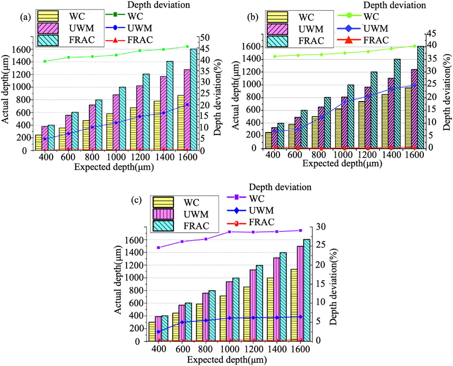
The measurement depth and depth deviation of blind holes: (a) tungsten steel electrode, (b) brass electrode, and (c) copper electrode (frequency = 130 kHz, pulse width = 5 µs, current = 4.5, voltage = 90 V, gain coefficient = 30).
3.2 The effects of compensation methods under different pulses on the roundness factor
With short pulse power supply processing, the roundness factor F round values of blind holes processed by tungsten steel and brass electrodes were shown in Figure 5. When the WC method was adopted, the deviations from the expected depths were very large, and both of them showed a downward trend. When UWM was adopted, the depth deviations of both were smaller. Compared with the WC method, the F round values were larger, but they also showed a downward trend with the increase of blind hole depth. When the FRAC method was adopted, the actual depths of the blind holes were close to the expected depths, so the F round values were higher than that of the previous two methods. It was obvious from the figures that the F round values of these three methods all showed a sharp downward trend, which meant that with increasing the discharge time, the electrode wear was more serious, and the actual removal of workpiece material was less.

The roundness factor of blind holes: (a) tungsten steel electrode; (b) brass electrode; (c) copper electrode (frequency = 120 kHz, pulse width = 3 µs, current = 2.5, voltage = 90 V, gain coefficient = 15).
The roundness factor F round values of blind holes processed by tungsten steel, brass, and copper electrodes with long pulse power processing are shown in Figure 6. In the WC method of tungsten steel and brass electrode, the electrode wear of the long pulse power supply was large, and the actual removal of workpiece material was less than that of the short pulse power supply under the same feed depth. Thus, the F round value was smaller. In UWM, the actual processing depth of the blind hole of three-electrode materials was deeper than that of the WC method and the volume of the blind hole was larger. Besides, the F round value was larger. But it also presented a downward trend with the increase of the blind hole depth. When the FRAC method was adopted, it was similar to short-pulse power supply processing and the F round value decreased with the increase of depth. In addition, the change of the copper electrode F round value did not show a tendency of steep decline when machining blind holes with brass and tungsten steel electrodes, which meant that the material removal of the workpiece tended to be ideal and conformed to the normal EDM rules.

The roundness factor of blind holes; (a) tungsten steel electrode: (b) brass electrode; (c) copper electrode (frequency = 130 kHz, pulse width = 5 µs, current = 4.5, voltage = 90 V, gain coefficient = 30).
3.3 The effects of the FRAC method under different pulses on the deep morphology
Figure 7 shows the blind holes are processed by tungsten steel electrode under the short-pulse power supply. The size of the cone at the bottom of the hole would gradually increase with the increase of the blind hole depth. This was attributed to the debris that were not discharged in time, which accumulated on the side wall at the bottom of the hole and the discharge occurred between the machining debris and the side wall of the electrode, resulting in the wear of the electrode side.

Blind holes processed by tungsten steel electrode: (a) the 3D morphology; (b) the SEM image (frequency = 120 kHz, pulse width = 3 µs, current = 2.5, voltage = 90 V, gain coefficient = 15).
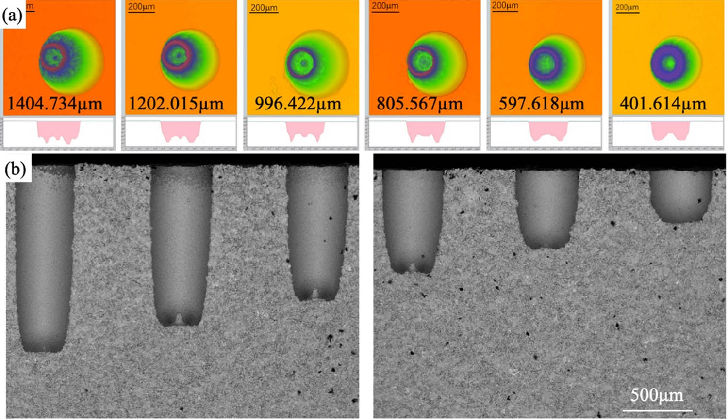
Figure 8 shows that the blind holes are processed by tungsten steel electrodes under the long-pulse power supply. The size of the cone at the bottom of the hole would gradually increase with the increase of the blind hole depth. The trend is the same as the short-pulse power supply.

Blind holes processed by tungsten steel electrode: (a) the 3D morphology; (b) the SEM image (frequency = 130 kHz, pulse width = 5 µs, current = 4.5, voltage = 90 V, gain coefficient = 30).
Figure 9 shows that the blind holes are processed by brass electrodes under the long-pulse power supply. The size of the cone at the bottom of the hole would increase with the increase of the blind hole depth. As shown in Figure 10, however, different from the short-pulse power supply, when the blind holes are processed by brass electrode under the long-pulse power supply, the cone at the bottom of the hole had disappeared. The increased side wears further led to the increase of blind hole taper, which meant that when only part of the workpiece material at the bottom of the blind hole was eroded, the processing space between the workpiece and the electrode becomes narrow, causing the compensation processing to become difficult and resulting in the electrode short circuit easy to be prone. Therefore, when the blind hole depth reached the maximum for the FRAC method, it was difficult to continue processing.
Blind holes processed by brass electrode: (a) the 3D morphology; (b) the SEM image (frequency = 120 kHz, pulse width = 3 µs, current = 2.5, voltage = 90 V, gain coefficient = 15).
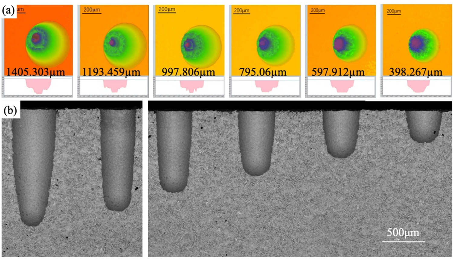
Blind holes processed by brass electrode: (a) the 3D morphology; (b) the SEM image (frequency = 130 kHz, pulse width = 5 µs, current = 4.5, voltage = 90 V, gain coefficient = 30).
However, it can be seen from Figure 11 that when the copper electrode was used in the FRAC method, the three-dimensional morphology was ideal with no cones or steps. Thus, compared with the former two kinds of electrode processing, copper had the best electrical conductivity, and the discharge between the two poles was easier and more frequent. In view of this feature, the copper electrode may be conducive to the formation of smaller debris, so it is easier to discharge at the discharge gap, reducing the bottom accumulation to a certain extent.

Blind holes processed by copper electrode: (a) the 3D morphology; (b) the SEM image (frequency = 130 kHz, pulse width = 5 µs, electric current = 4.5, voltage = 90 V, gain coefficient = 30).
3.4 The effects of EDM parameter and a different electrode on the precision of blind holes
To study the effect of different EDM discharge energy and electrode material on the machining accuracy of blind holes. The depth deviation and roundness factor were compared on different EDM discharge energy and electrode material, as shown in Figures 12 and 13. When using a long-pulse power supply, the processing accuracy of blind holes was better than using a short-pulse power supply, whether using a tungsten steel electrode or brass electrode. More debris was produced under the same conditions, the discharge energy of the long-pulse power supply in EDM was larger. The machining accuracy of the blind hole has greatly affected the accumulation of debris in the machining gap. With increasing the machining depth, the machining accuracy of the blind hole was reduced. But in the method of FEAC, the depth deviation of the blind hole had little effect under the long-pulse power supply, which proved that the FRAC method can effectively improve the machining accuracy.

The depth deviation under different pulse of blind holes: (a) tungsten steel electrode; (b) brass electrode (Short-pulse power: frequency = 120 kHz, pulse width = 3 µs, current = 2.5, voltage = 90 V, gain coefficient = 15; long-pulse power: frequency = 130 kHz, pulse width = 5 µs, current = 4.5, voltage = 90 V, gain coefficient = 30).

The roundness factor under different pulse of blind holes: (a) tungsten steel electrode; (b) brass electrode (Short-pulse power: frequency = 120 kHz, pulse width = 3 µs, current = 2.5, voltage = 90 V, gain coefficient = 15; Long-pulse power: frequency = 130 kHz, pulse width = 5 µs, current = 4.5, voltage = 90 V, gain coefficient = 30).
The short-pulse power supply of the blind hole can help obtain high machining accuracy, but the discharge energy is low during machining, reducing the machining efficiency. Using copper electrodes to process blind holes can obtain higher micro-holes processing accuracy than the other two electrodes under the long-pulse power, as shown in Figure 14. Because the conductivity of the copper electrode was better, and the debris was smaller produced by repeated discharge, which was easy to discharge from the machining gap improving the machining accuracy of blind holes. Compared with the latest reports, based on volume removal per discharge (VRD) in reverse-micro-electrical-discharge machining [19,20], the new method in this work had higher precision (e.g., the depth deviations processed by the copper electrodes were less than 0.43%, and the average roundness factor was 79.8%), simpler experimental method.

The precision of blind holes by different electrode materials: (a) the depth deviation; (b) the roundness factor (frequency = 130 kHz, pulse width = 5 µs, current = 4.5, voltage = 90 V, gain coefficient = 30).
4 Conclusion
Electrode wear is unavoidable and has a detrimental effect on machining precision. A simple and effective fixed reference axial compensation method is proposed to obtain the high precision micro-hole drilled in the TC4 workpiece. The purpose of this study is to compare the influence of machining precision without compensation, with fixed reference axial compensation, and with uniform wear compensation on micro-hole machining precision. Additionally, a sequence of experiments is conducted. The following summarizes the study’s principal findings:
The FRAC technique determined that the depth deviation was less than 0.43%, with a minimum deviation of 0.106 µm from the intended depth. Additionally, as compared to the WC and UWM methods, the FRAC method improves the depth deviation by approximately 73.3 and 50.2%, respectively.
The electrode material was discovered to be the most critical component in determining the precision of micro-holes. For instance, when drilling a micro-hole with a copper tool electrode to a depth of 1.6 mm, the depth deviation is less than 0.213% and the roundness factor is approximately 73.4%. While the depth deviation of the brass electrode is less than 0.3975 and the roundness factor is 53.2%, the depth deviation of the tungsten electrode is less than 0.721%, and the roundness factor is 62.7%
The processing accuracy under long-pulse power supply was worse than that of short-pulse power supply, such as a higher depth deviation of blind hole and lower roundness factor.
The combination of the copper electrode and long-pulse power supply can obtain high machining accuracy of a blind hole in the TC4 workpiece. The depth deviations processed by the copper electrodes were less than 0.43%, and the average roundness factor was 79.8%.
The FRAC method can realize the accurate compensation and reach the expected depth holes processing. As a result, it can be used in a wide variety of high-end manufacturing applications to increase the precision of micro-holes for micro features.
Nomenclature
- EDM
-
electrical discharge machining
- FRAC
-
fixed reference axial compensation
- TWR
-
tool-electrode wear rate
- MRR
-
material removal rate
- VRD
-
volume removal per discharge
- UWM
-
uniform wear method
- WC
-
without compensation
- WEDG
-
wire electrical discharge grinding
- V actual
-
actual volume
- V expected
-
expected volume
- F round
-
roundness factor
Acknowledgments
The authors are grateful for the support provided by Yongkang Zhang at the Guangdong University of Technology.
-
Funding information: This work is partly supported by the the National Natural Science Foundation of China (No. 5217050334, U1608259), the Science and Technology Planning Project of Guangdong Province of China (No. 2017KZ010103).
-
Author contributions: Conceptualization, Jiangwen Liu and Chaohui Lin; methodology, Jiangwen Liu and Chaohui Lin; software, Jiaming Li, Shiyong Liang, and Junfeng Gou; validation, Chaohui Lin Jiangwen Liu Jiaming Li and Junfeng Gou; formal analysis, Chaohui Lin and Shiyong Liang; investigation, Chaohui Lin and Shiyong Liang; resources, Chaohui Lin; data curation, Chaohui Lin; writing – original draft preparation, Chaohui Lin and Yao Li; writing – review and editing, Chaohui Lin and Junfeng Gou; visualization, Shiyong Liang and Yao Li; supervision, Jiangwen Liu; funding acquisition, Jiangwen Liu. All authors have read and agreed to the published version of the manuscript.
-
Conflict of interest: Authors state no conflict of interest.
-
Data availability statement: The datasets generated during and/or analyzed during the current study are available from the corresponding author on reasonable request.
References
[1] Prakash, C., S. Singh, C. Pruncu, V. Mishra, G. Królczyk, D. Pimenov, et al. Surface modification of Ti–6Al–4V alloy by electrical discharge coating process using partially sintered Ti–Nb electrode. Materials, Vol. 12, 2019, pp. 1006–1022.10.3390/ma12071006Search in Google Scholar
[2] Singh, N. K., Y. Singh, and A. Sharma. Experimental investigation of flushing approaches on EDM machinability during machining of titanium alloy. Materials Today: Proceedings, Vol. 38, 2020, pp. 139–145.10.1016/j.matpr.2020.06.165Search in Google Scholar
[3] Tiwary, A. P., B. B. Pradhan, and B. Bhattacharyya. Influence of various metal powder mixed dielectric on micro-EDM characteristics of Ti–6Al–4V. Materials and Manufacturing Processes, Vol. 34, No. 10, 2019, pp. 1103–1119.10.1080/10426914.2019.1628265Search in Google Scholar
[4] Thangamani, G., M. Thangaraj, K. Moiduddin, S. H. Mian, H. Alkhalefah, and U. Umer. Performance analysis of electrochemical micro machining of titanium (Ti–6Al–4V) alloy under different electrolytes concentrations. Metals - Open Access Metallurgy Journal, Vol. 11, 2021, pp. 247–259.10.3390/met11020247Search in Google Scholar
[5] Li, J., G. Yin, C. Wang, X. Guo, and Z. Yu. Prediction of aspect ratio of a micro hole drilled by EDM. Journal of Mechanical Science and Technology, Vol. 2, 2013, pp. 185–190.10.1007/s12206-012-1214-9Search in Google Scholar
[6] Saravanan, M., V. B. Raja, K. Palanikumar, P. Vaidyaa, S. Sundar, and M. S. Prakash. Laser drilling parameter optimization for Ti6Al4v alloy. Materials Today: Proceedings, Vol. 2, 2021, pp. 125–136.10.1016/j.matpr.2021.02.538Search in Google Scholar
[7] Plaza, S., J. A. Sanchez, E. Perez, R. Gil, B. Izquierdo, N. Ortega, and et al. Experimental study on micro EDM-drilling of Ti6Al4V using helical electrode. Precision Engineering, Vol. 38, 2014, pp. 821–827.10.1016/j.precisioneng.2014.04.010Search in Google Scholar
[8] Lin, Y. C., B. H. Yan, and Y. S. Chang. Machining characteristics of titanium alloy (Ti–6Al–4V) using a combination process of EDM with USM. Journal of Materials Processing Technology, Vol. 104, 2000, pp. 171–177.10.1016/S0924-0136(00)00539-2Search in Google Scholar
[9] Patel Gowdru Chandrashekarappa, M., S. Kumar, D. Y. Pimenov, and K. Giasin. Experimental analysis and optimization of EDM parameters on HcHcr steel in Context with different electrodes and dielectric fluids using hybrid Taguchi-based PCA-utility and Critic-utility approaches. Metals, Vol. 11, 2021, pp. 419–442.10.3390/met11030419Search in Google Scholar
[10] Ferraris, E., V. Castiglioni, F. Ceyssens, M. Annoni, B. Lauwers, and D. Reynaerts. EDM drilling of ultra-high aspect ratio micro holes with insulated tools. CIRP Annals, Vol. 62, 2013, pp. 191–194.10.1016/j.cirp.2013.03.115Search in Google Scholar
[11] Jahan, M. P., Y. S. Wong, and M. Rahman. Evaluation of the effectiveness of low frequency workpiece vibration in deep-hole micro-EDM drilling of tungsten carbide. Journal of Manufacturing Processes, Vol. 14, 2012, pp. 343–359.10.1016/j.jmapro.2012.07.001Search in Google Scholar
[12] Singh, K. N., P. M. Pandey, and K. K. Singh. Experimental investigations into the performance of EDM using argon gas-assisted perforated electrodes. Materials and Manufacturing Processes, Vol. 31, 2016, pp. 1872–1878.10.1080/10426914.2016.1221079Search in Google Scholar
[13] Hirao, A., H. Gotoh, and T. Tani. Some effects on EDM characteristics by assisted ultrasonic vibration of the tool electrode. Procedia CIRP, Vol. 68, 2018, pp. 76–80.10.1016/j.procir.2017.12.025Search in Google Scholar
[14] Sivaprakasam, P., J. U. Prakash, and P. Hariharan. Enhancement of material removal rate in magnetic field-assisted micro electric discharge machining of AMCs. International Journal of Ambient Energy, Vol. 1, 2019, pp. 143–750.10.1080/01430750.2019.1653979Search in Google Scholar
[15] Bozdana, A. T. and N. K. Al-Karkhi. Comparative experimental investigation and gap flow simulation in electrical discharge drilling using new electrode geometry. Mechanical Sciences, Vol. 8, 2017, pp. 289–298.10.5194/ms-8-289-2017Search in Google Scholar
[16] Kumar, R., A. Kumar, and I. Singh. Electric discharge drilling of micro holes in CFRP laminates. Journal of Materials Processing Technology, Vol. 259, 2018, pp. 150–158.10.1016/j.jmatprotec.2018.04.031Search in Google Scholar
[17] Aligiri, E., S.-H. Yeo, and P.-C. Tan. A new tool wear compensation method based on real-time estimation of material removal volume in micro-EDM. Journal of Materials Processing Technology, Vol. 210, 2010, pp. 2292–2303.10.1016/j.jmatprotec.2010.08.024Search in Google Scholar
[18] Nirala, C. K. and P. Saha. Precise µEDM-drilling using real-time indirect tool wear compensation. Journal of Materials Processing Technology, Vol. 240, 2017, pp. 176–189.10.1016/j.jmatprotec.2016.09.024Search in Google Scholar
[19] Nirala, C. K. and P. Saha. A new approach of tool wear monitoring and compensation in RµEDM process. Materials and Manufacturing Processes, Vol. 31, 2016, pp. 483–494.10.1080/10426914.2015.1058950Search in Google Scholar
[20] Malayath, G., S. Katta, A.-M. Sidpara, and S. Deb. Length-wise tool wear compensation for micro electric discharge drilling of blind holes. Measurement, Vol. 134, 2019, pp. 888–896.10.1016/j.measurement.2018.12.047Search in Google Scholar
[21] Singh, S., S. Maheshwari, and P. C. Pandey. Some investigations into the electric discharge machining of hardened tool steel using different electrode materials – ScienceDirect. Journal of Materials Processing Technology, Vol. 149, 2004, pp. 272–277.10.1016/j.jmatprotec.2003.11.046Search in Google Scholar
[22] Patel, M., M. Patel, and C. P. Patel. Analysis of different tool material on MRR and surface roughness of mild steel in EDM. International Journal of Engineering Research & Applications, Vol. 1, 2011, pp. 394–397.Search in Google Scholar
[23] Yu, Z. Y., T. Masuzawa, and M. Fujino. Micro-EDM for three-dimensional cavities – development of uniform wear method. CIRP Annals, Vol. 47, 1998, pp. 169–172.10.1016/S0007-8506(07)62810-8Search in Google Scholar
© 2021 Chaohui Lin et al., published by De Gruyter
This work is licensed under the Creative Commons Attribution 4.0 International License.
Articles in the same Issue
- Review Articles
- A review on filler materials for brazing of carbon-carbon composites
- Nanotechnology-based materials as emerging trends for dental applications
- A review on allotropes of carbon and natural filler-reinforced thermomechanical properties of upgraded epoxy hybrid composite
- High-temperature tribological properties of diamond-like carbon films: A review
- A review of current physical techniques for dispersion of cellulose nanomaterials in polymer matrices
- Review on structural damage rehabilitation and performance assessment of asphalt pavements
- Recent development in graphene-reinforced aluminium matrix composite: A review
- Mechanical behaviour of precast prestressed reinforced concrete beam–column joints in elevated station platforms subjected to vertical cyclic loading
- Effect of polythiophene thickness on hybrid sensor sensitivity
- Investigation on the relationship between CT numbers and marble failure under different confining pressures
- Finite element analysis on the bond behavior of steel bar in salt–frost-damaged recycled coarse aggregate concrete
- From passive to active sorting in microfluidics: A review
- Research Articles
- Revealing grain coarsening and detwinning in bimodal Cu under tension
- Mesoporous silica nanoparticles functionalized with folic acid for targeted release Cis-Pt to glioblastoma cells
- Magnetic behavior of Fe-doped of multicomponent bismuth niobate pyrochlore
- Study of surfaces, produced with the use of granite and titanium, for applications with solar thermal collectors
- Magnetic moment centers in titanium dioxide photocatalysts loaded on reduced graphene oxide flakes
- Mechanical model and contact properties of double row slewing ball bearing for wind turbine
- Sandwich panel with in-plane honeycombs in different Poisson's ratio under low to medium impact loads
- Effects of load types and critical molar ratios on strength properties and geopolymerization mechanism
- Nanoparticles in enhancing microwave imaging and microwave Hyperthermia effect for liver cancer treatment
- FEM micromechanical modeling of nanocomposites with carbon nanotubes
- Effect of fiber breakage position on the mechanical performance of unidirectional carbon fiber/epoxy composites
- Removal of cadmium and lead from aqueous solutions using iron phosphate-modified pollen microspheres as adsorbents
- Load identification and fatigue evaluation via wind-induced attitude decoupling of railway catenary
- Residual compression property and response of honeycomb sandwich structures subjected to single and repeated quasi-static indentation
- Experimental and modeling investigations of the behaviors of syntactic foam sandwich panels with lattice webs under crushing loads
- Effect of storage time and temperature on dissolved state of cellulose in TBAH-based solvents and mechanical property of regenerated films
- Thermal analysis of postcured aramid fiber/epoxy composites
- The energy absorption behavior of novel composite sandwich structures reinforced with trapezoidal latticed webs
- Experimental study on square hollow stainless steel tube trusses with three joint types and different brace widths under vertical loads
- Thermally stimulated artificial muscles: Bio-inspired approach to reduce thermal deformation of ball screws based on inner-embedded CFRP
- Abnormal structure and properties of copper–silver bar billet by cold casting
- Dynamic characteristics of tailings dam with geotextile tubes under seismic load
- Study on impact resistance of composite rocket launcher
- Effects of TVSR process on the dimensional stability and residual stress of 7075 aluminum alloy parts
- Dynamics of a rotating hollow FGM beam in the temperature field
- Development and characterization of bioglass incorporated plasma electrolytic oxidation layer on titanium substrate for biomedical application
- Effect of laser-assisted ultrasonic vibration dressing parameters of a cubic boron nitride grinding wheel on grinding force, surface quality, and particle morphology
- Vibration characteristics analysis of composite floating rafts for marine structure based on modal superposition theory
- Trajectory planning of the nursing robot based on the center of gravity for aluminum alloy structure
- Effect of scan speed on grain and microstructural morphology for laser additive manufacturing of 304 stainless steel
- Influence of coupling effects on analytical solutions of functionally graded (FG) spherical shells of revolution
- Improving the precision of micro-EDM for blind holes in titanium alloy by fixed reference axial compensation
- Electrolytic production and characterization of nickel–rhenium alloy coatings
- DC magnetization of titania supported on reduced graphene oxide flakes
- Analytical bond behavior of cold drawn SMA crimped fibers considering embedded length and fiber wave depth
- Structural and hydrogen storage characterization of nanocrystalline magnesium synthesized by ECAP and catalyzed by different nanotube additives
- Mechanical property of octahedron Ti6Al4V fabricated by selective laser melting
- Physical analysis of TiO2 and bentonite nanocomposite as adsorbent materials
- The optimization of friction disc gear-shaping process aiming at residual stress and machining deformation
- Optimization of EI961 steel spheroidization process for subsequent use in additive manufacturing: Effect of plasma treatment on the properties of EI961 powder
- Effect of ultrasonic field on the microstructure and mechanical properties of sand-casting AlSi7Mg0.3 alloy
- Influence of different material parameters on nonlinear vibration of the cylindrical skeleton supported prestressed fabric composite membrane
- Investigations of polyamide nano-composites containing bentonite and organo-modified clays: Mechanical, thermal, structural and processing performances
- Conductive thermoplastic vulcanizates based on carbon black-filled bromo-isobutylene-isoprene rubber (BIIR)/polypropylene (PP)
- Effect of bonding time on the microstructure and mechanical properties of graphite/Cu-bonded joints
- Study on underwater vibro-acoustic characteristics of carbon/glass hybrid composite laminates
- A numerical study on the low-velocity impact behavior of the Twaron® fabric subjected to oblique impact
- Erratum
- Erratum to “Effect of PVA fiber on mechanical properties of fly ash-based geopolymer concrete”
- Topical Issue on Advances in Infrastructure or Construction Materials – Recycled Materials, Wood, and Concrete
- Structural performance of textile reinforced concrete sandwich panels under axial and transverse load
- An overview of bond behavior of recycled coarse aggregate concrete with steel bar
- Development of an innovative composite sandwich matting with GFRP facesheets and wood core
- Relationship between percolation mechanism and pore characteristics of recycled permeable bricks based on X-ray computed tomography
- Feasibility study of cement-stabilized materials using 100% mixed recycled aggregates from perspectives of mechanical properties and microstructure
- Effect of PVA fiber on mechanical properties of fly ash-based geopolymer concrete
- Research on nano-concrete-filled steel tubular columns with end plates after lateral impact
- Dynamic analysis of multilayer-reinforced concrete frame structures based on NewMark-β method
- Experimental study on mechanical properties and microstructures of steel fiber-reinforced fly ash-metakaolin geopolymer-recycled concrete
- Fractal characteristic of recycled aggregate and its influence on physical property of recycled aggregate concrete
- Properties of wood-based composites manufactured from densified beech wood in viscoelastic and plastic region of the force-deflection diagram (FDD)
- Durability of geopolymers and geopolymer concretes: A review
- Research progress on mechanical properties of geopolymer recycled aggregate concrete