Mechanical property of octahedron Ti6Al4V fabricated by selective laser melting
-
Yun Zhai


Abstract
The stress shielding effect is a critical issue for implanted prosthesis due to the difference in elastic modulus between the implanted material and the human bone. The adjustment of the elastic modulus of implants by modification of the lattice structure is the key to the research in the field of implanted prosthesis. Our work focuses on the basic unit structure of octahedron Ti6Al4V. The equivalent elastic modulus and equivalent density of porous structure are optimized according to the mechanical properties of human bone tissue by adjusting the edge diameter and side length of octahedral lattice. Macroscopic long-range ordered arrangement of lattice structures is fabricated by selective laser melting (SLM) technology. Finite element simulation is performed to calculate the mechanical property of octahedron Ti6Al4V. Scanning electronic microscopy is applied to observe the microstructure of octahedron alloy and its cross section morphology of fracture. Standard compression test is performed for the stress–strain behavior of the specimen. Our results show that the octahedral lattice with the edge diameter of 0.4 mm and unit cell length of 1.5 mm has the best mechanical property which is close to the human bone. The value of equivalent elastic modulus increases with the increase in the edge diameter. The SLM technology proves to be an effective processing way for the fabrication of complex microstructures with porosity. In addition, the specimen exhibits isotropic mechanical performance and homogeneity which significantly meet the requirement of implanted prosthetic medical environment.
1 Introduction
Titanium alloys are frequently applied as forming materials for prosthetic implants for the human body, due to its good mechanical properties, excellent corrosion resistance, and high biological compatibility [1,2,3]. However, nowadays, most of the clinical titanium alloy structures are shaped or cut by mold forging, casting, and powder metallurgy. These traditional processing methods have congenital disadvantages with high cost, long processing cycle, and inability to shape complex geometry [4,5]. 3D printing, also called additive manufacturing (AM), is a technique using raw materials like powder metal or plastic to construct objects layer by layer according to digital model files, which can quickly shape a customized complex structure for medical application [6]. Although the structure of titanium alloy has excellent comprehensive physical and chemical properties, there is a “stress shielding” phenomenon which cannot be ignored for the implant prosthesis application [7,8]. Nowadays few scholars pay attention to the optimization of the geometric parameters of the lattice of porous titanium alloys, regarding to the AM process and complex biomechanical scenarios. No systematic quantitative relationship has been established between titanium alloy microstructure and macroscopic mechanical properties, which can be the guiding theory for the elimination of stress shielding effect.
The appearance of bone implants with porous structures has a profound impact on the improvement and development of the implants. Most parts of the body that bear heavy loads such as the femur and tibia have bone damage, and they need to be replaced with solid metal implants with high strength and mechanical properties to help achieve physical demand [9,10]. At present, the metal materials used for orthopedic implantation mainly include stainless steel, CoCr alloy, titanium and titanium alloy, graphene, ceramic materials, polymer materials, etc., [11,12,13]. One of the earliest metal materials used in clinical use is stainless steel. However, the environment affects the stainless steel, resulting in friction corrosion and loosening [14]. Currently, the most widely used implant material is titanium alloy represented by Ti6Al4V. It has good comprehensive mechanical properties and excellent corrosion resistance, while the elastic mismatch is a main problem [15]. Recent studies show that tantalum metal has higher volumetric porosity and higher surface friction coefficient. The corresponding research is still in its infancy, which focuses on its higher density than other materials [16]. The hardness of tantalum metal’s solid structure is much greater than that of bone. This creates a noticeable “stress shielding” phenomenon. The solid structure of tantalum metal leads to no long-term stable fixation between the implant and bone tissue, which leads to the phenomenon of loosening and displacement. Some scholars have studied the elastic modulus and biological properties of polyether ether ketone material, which is very suitable for implantation, and can also solve the problem of excessive rigidity of metal implants. The friction performance can be enhanced by modification to make it more suitable for the physical demand of implantation. With the development of 3D printing technology, hydraulic coagulation is widely used, and its non-toxicity and good biocompatibility make it a newer bone tissue engineering scaffold material.
To obtain better mechanical and biological properties, the implanted prosthesis can be replaced with a partial porous structure. This increases the area of contact with bone tissue and effectively reduces the weight and elastic modulus, decreasing the bone interface stress [17]. Ziheng studied the selective laser melting (SLM) molding process of the tibia replacement prosthesis. His results shows that, when the thickness of the printing layer is 0.03 mm, the laser power is 150 W, and the scanning speed is 400 mm·s−1, the density of the formed parts reaches more than 98%, and the yield strength of the porous structure after heat treatment reaches 1038.92 MPa [18]. Wei used a three-section structure of porous end, middle thread, and solid neck to study dental implants, which effectively reduced the elastic modulus and stress shielding phenomenon [19]. Zhao Pei’s team used electron beam melting (EBM) to design the porous structure. They proposed a rapid method for the measurement of pore size by combining electron microscopy and microcomputed tomography [20]. Gibson’s team analyzed a number of different forms of porous structures. A model is established to describe the performance of elastic modulus, which provides a theoretical basis for the calculation of theoretical parameters of porous structures [21].
There are many porous structures to choose from, ranging from millimeter level to nanometer level. The macroscopical effects of the geometrical parameters like the diameter of the lattice can also be modeled with some reduced model of higher order [22]. Yang Jiawei and others have provided ideas for the study of nanostructure systems by studying the characteristics of diamond structures. At the same time, nanostructures of different materials used in the biomedicine fields have provided greater help. Nanoengineering has expanded the value of metal materials in bioengineering, and nanoscale pore structures are also commonly found in various coatings. Wang Junling and others measured the porosity of bovine bone and its millimeter-level pore size, and used pressure to test its corresponding cell proliferation rate. The greater the pressure, the higher the rate of increase, which provides a theoretical basis for the micromechanical structure of bone tissue engineering.
There are various algorithms to build unit structure models which build up the quantitative correlation between structural parameters and mechanical properties [23]. Liu et al. carried out a study on the structural unit of the regular octahedral space extension arm. They obtained the relationship between the force and deformation of the system structure through the analysis method of two force bars and verified the characteristics of the regular octahedral structure, such as lightweight and good stiffness [24]. Wang’s team studied the design rules and key points of the precise fabrication of porous structures by the SLM process. The proposed rules for the design of octahedral cell structures are that a critical tilt angle between 30° and 90° is suitable for SLM processes. The angle of inclination of a regular octahedron is 45°. The cell structure is suitable for SLM forming. The aperture error is less than 3% [25].
The most mentioned literature regarding artificial medical prosthesis mainly focuses on the selection of solid implant materials and surface coating modification, whereas the actual clinical medical scenarios have more complex requirements for implants. Two critical issues are the elimination of stress shielding effect and the isotropic performance that satisfies the actual physical demand. In addition, a rapid molding processing technology is needed to meet the requirement of the customized fabrication of complicated geometry. The corresponding theory including the evolution mechanism from microstructure to macroscopic mechanical properties and the arrangement of the lattice structure in a long-range order have not been systematically investigated.
Considering the above existing issues in the field of artificial implant prosthesis, this article studies the regular octahedron as the unit structure by adjusting the edge diameter and unit size to optimize the geometry parameter of the porous structure. Finite element analysis is applied to design the microstructure subjected to compression force. The long-range orderly arrangement of the Ti6Al4V octahedron is realized by the SLM technology. The mechanical properties characterization verifies the consistency of the equivalent elastic modulus between our fabricated specimen and the human bone. The isotropy of the mechanical performance is confirmed by the layer angle experiment. The connection between the geometry parameters and equivalent elastic modulus is obtained, which provides a certain theoretical basis for the reduction of stress shielding.
2 Design and simulation
2.1 The establishment of geometric model and simulation analysis
There are three popular porous structures regarding to the selective laser sintering (SLS) process: (1) Cubic unit structure. It has excellent fatigue resistance, while the bending resistance ability is poor. (2) Diagonal-type unit structure. Its bending resistance is better, while the structure is vulnerable to stress concentration. (3) Body-centered cubic unit structure, which has the advantage of convenient manufacture and stable mechanical properties. The octahedral porous structure presented in this article combines the advantages of multiple structures. The molding angle among edges is 45°, which provides a structure stability and adjustable mechanical properties. Implant porous structure commonly needs to meet the physical demand of complex biomechanical conditions. The isotropic mechanical properties are more suitable for clinical medical scenarios. Gibson’s theory indicates that there is a quantitative relationship between the elastic modulus and the volume ratio of porous structures [21]. Regulation of porous structural volume ratio can be achieved by adjusting the edge diameter and edge length of the lattices, which leads to the manipulation of the equivalent elastic modulus.
Based on the current research, we summarize the engineering parameters of octahedron Ti6Al4V that satisfy the medical implant scenario. The edge diameter should be larger than 0.15 mm, the porosity ratio should range in 30–90%, and the aperture size should range in 100–800 µm. To minimize the stress shielding effect and make the density of implant material close to that of human bone, the equivalent elastic modulus should be in the range of 0.1–20 GPa and the density should range in 0.2–1.5 g·cm−3, as shown in Table 1.
| Edge diameter (mm) | Porosity (%) | Aperture size (µm) | Equivalent elastic modulus (GPa) | Mass density (g·cm−3) |
|---|---|---|---|---|
| ≥0.15 (Geometrical properties) | 30–90 (Bone tissue structure) | 100–800 (Bone tissue structure) | 0.1–20 (Femur elastic modulus range) | 0.2–1.5 (Normal bone density) |
Based on the design basis of the porous structure of the implant, the basic unit of the regular octahedron is established. The unit structure is shown in Figure 1. Ten types of regular octahedral structures with different parameters are designed. The parameters are shown in Table 2. The unit side length and regular octahedral edge diameter are the independent variables. The pore size, porosity, equivalent elastic modulus, and equivalent density are dependent variables. The values of the dependent variables in the table are calculated by the Ashby–Gibson model formula [28]. We study the influence of edge diameter and unit cell edge length on the mechanical performance of porous structure.
Model establishment: A regular octahedron is sketched in the 3D software. We set up the edges of the octahedron first and then form the unit octahedron by mirror operation. Finally, the regular octahedral structure is arranged in a long-range order to form a porous structure with a cube side length size of 12 mm, as shown in Figure 2. The porous structure of ten groups of normal octahedrons with different geometric parameters are constructed by adjusting cell length and edge diameter. After checking the model for incision and interference, meshing and finite element calculation of the model are carried out.
Material property assignment: The elastic modulus is assigned to be 28.78 GPa, the density is assigned to be 4,172 kg·m−3, and the Poisson’s ratio is assigned to be 0.3 [29].
Meshing: Since the model is built using array processing, and the size of a single model is small, the calculation time and model calculation accuracy must be considered comprehensively when meshing. For the model with a unit cell side length of 1.5 mm, the minimum mesh size is 0.2 mm. For the model with a unit cell side length of 2 mm, the minimum mesh size is 0.1 mm. The meshing map is shown in Figure 3.
Boundary conditions: The mechanical property of the porous structure is an important factor for its performance as implanted material in the human body. This article uses finite element simulation analysis to simulate its stress and strain behavior under compression [30,31,32,33]. Supports-Fixed condition is applied to fix the lower surface of the porous structure and Supports-Displacement is used to apply a 1% downward displacement on the upper surface [34]. We perform simulation analysis of ten groups of models and observe the stress and strain relationship, and the simulation value of elastic modulus is calculated [35,36,37,38]. The constraint effect is shown in Figure 4.
The finite element analysis results of porous structure: The equivalent elastic modulus of the porous structure is a critical parameter to verify the consistency between simulation analysis and theoretical calculation. As for the simulation calculation, the lower surface is subjected to a fixed boundary condition, while a distribution force is exerted at the upper surface. Assuming equilibrium condition exists during the compression, the fixed lower surface will be subjected to an upward supporting force. A fixed support boundary condition is given in the finite element software to calculate the equivalent elastic modulus according to Hooke’s Law:
where σ is the stress value of the porous structure; F re is the total supporting reaction force of the porous structure; S is the cross-sectional area of the porous structure; ε is the strain value of the porous structure; L is the displacement of the porous structure; and H is the original length in the direction of compression force. The equivalent elastic modulus is calculated by:

Lattice structure and side length, edge diameter, and aperture of the lattice.
Structural design parameters of regular octahedral porous structure
| Sequence | Unit structure side length (mm) | Edge diameter of regular octahedron (mm) | Aperture (µm) | Porosity (%) | Equivalent elastic modulus (GPa) | Equivalent density (g·cm−3) |
|---|---|---|---|---|---|---|
| 1 | 1.5 | 0.4 | 660.66 | 63.78 | 2.51 | 1.51 |
| 2 | 1.5 | 0.45 | 610.66 | 55.93 | 3.72 | 1.84 |
| 3 | 1.5 | 0.5 | 560.66 | 47.77 | 5.23 | 2.18 |
| 4 | 1.5 | 0.55 | 510.66 | 39.44 | 7.04 | 2.53 |
| 5 | 1.5 | 0.6 | 460.66 | 31.07 | 9.11 | 2.87 |
| 6 | 2 | 0.6 | 814.21 | 55.92 | 3.72 | 1.84 |
| 7 | 2 | 0.65 | 764.21 | 49.82 | 4.82 | 2.09 |
| 8 | 2 | 0.7 | 714.21 | 43.62 | 6.09 | 2.35 |
| 9 | 2 | 0.75 | 664.21 | 37.35 | 7.53 | 2.61 |
| 10 | 2 | 0.8 | 614.21 | 31.07 | 9.11 | 2.87 |

Modeling process of porous structure.

The grid division meshing map.

Boundary condition setting of porous structure.
Based on the abovementioned meshing principle and loading conditions, the finite element analysis and calculation are carried out. The calculation results of the porous structure of the unit cell of 1.5 mm and the unit cell of 2 mm are shown in Figures 5 and 6. As the 1.5 mm cell edge diameter increases from 0.4 to 0.6 mm, the equivalent elastic modulus increases from 3.24 to 9.99 GPa. As the 2 mm cell edge diameter increases from 0.6 to 0.8 mm, the equivalent elastic modulus increases from 4.41 to 9.79 GPa. It is preliminarily verified by simulation that the equivalent elastic modulus of the model falls into the design range. The model structure is preliminarily verified to be reasonable by the finite element calculation.

Stress distribution of 1.5 mm cell loaded with different edge diameters (a) 0.4 mm edge diameter stress map; (b) 0.45 mm edge diameter stress map; (c) 0.5 mm edge diameter stress map; (d) 0.55 mm edge diameter stress map; and (e) 0.6 mm edge diameter stress map.

Stress distribution of 2 mm cell loaded with different edge diameters (a) 0.6 mm edge diameter stress map; (b) 0.65 mm edge diameter stress map; (c) 0.7 mm edge diameter stress map; (d) 0.75 mm edge diameter stress map; and (e) 0.8 mm edge diameter stress map.
3 Experiments
3.1 The 3D printing of porous structure
3D printing technology is widely used in medicine. The complex pore structure cannot be formed by traditional processing methods as the molding effect is not good. 3D printing can solve this problem. By adjusting the processing parameters, a high printing accuracy can be achieved. Typical 3D printing technologies for metals include SLS, EBM, SLM, etc. Compared with other metal 3D technologies, SLM can achieve 98.65% density for titanium alloy products [20], and it is currently more widely used in medical implant material application. The manufacturing principle is shown in Figure 7. The protective gas is filled into the forming cavity, and the metal powder is evenly spread on the substrate through the powder spreading system. The substrate is used as the coordinate system. The vertical substrate direction is defined as the Z axis, and the parallel substrate direction is X and Y axes. Laser is irradiated on the substrate through the scanning system for molding, and each layer of the substrate is lowered to a certain distance to re-spread the powder. The process is repeated to complete the SLM molding layer by layer. Similar molding technology is widely used in the aerospace field and has good mechanical properties [39].

SLM forming schematic diagram.
The printing material powder is Ti6Al4V titanium alloy with diameter from 15 to 53 µm. The composition is shown in Table 3.
Chemical composition of Ti6Al4V titanium alloy powder
| Element | Ti | Al | V | Fe | C | N | H | O |
|---|---|---|---|---|---|---|---|---|
| Content (%) | 89.18 | 6.46 | 4.04 | 0.22 | 0.011 | 0.01 | 0.002 | 0.078 |
The bold value means the weight percent of titanium in the Ti6Al4V alloy is 89.18%.
The metal 3D printer is AM250 from British Renishaw company. The printing parameters are shown in Table 4. The electronic universal testing machine is UTM5105 from Shenzhen Sansi aspect Technology Co. Ltd. The scanning electron microscope (SEM) is SUPRA 55 from Carl Zeiss AG, Germany.
Processing parameters of Renishaw AM250 metal 3D printer
| Dot pitch | Line spacing | Laser power (W) | Single layer thickness (mm) | Exposure time (µs) | Scan speed (mm·s−1) | Laser energy density (J·mm−3) |
|---|---|---|---|---|---|---|
| 0.075 | 0.065 | 200 | 0.03 | 50 | 1,500 | 269.1 |
Magics 22.0 software is used to repair the STL file of the imported model and adjust the placement position according to the pre-spreading effect of the substrate as shown in Figure 9. Since the modeling direction is vertical to the substrate along the positive Z axis, the deposition direction of each layer remains horizontal. In order to increase the strength of the horizontal edge, the regular octahedron model is placed in the positive direction along the Z axis. Due to the cube geometry, the model is positioned forward to speed up the printing and save the printing materials. A substrate with a thickness of 0.6 mm is placed at the bottom of the model. The printing position is shown in Figure 8.

The model printing position and schematic diagram of model placement.
The substrate is preheated to 160°C. Argon gas is pumped into the working chamber for protection. When the oxygen concentration drops to 1,000 ppm, the printing process is initiated. The finished specimens are separated from the substrate by a wire cutting machine and cleaned by sandblasting and an ultrasonic cleaning machine. The final specimens are shown in Figure 9.

Ten specimens with different lattice geometry.
3.2 Structure characterization
The surface morphology of ten regular octahedron structures with different parameters is observed by SEM, as shown in Figures 10 and 11. The magnification is 14 times and 25 times. The SEM image shows that most of the structures have excellent quality with only few molding defects, as shown in the red circle in Figure 10(b) [40]. The edge diameter and hole diameter of the molded part is indicated by the yellow arrow in the image. The comparison among the surface morphology of the samples of different geometric sizes indicates that the roughness of the surface appearance increases to a varying degree with the increase in side length and edge diameter. The reason behind this observation is probably that the SLM processing tends to apply smaller laser spot for sintering when modeling the lattices in a smaller scale. The microstructure characterization demonstrates that the SLM technology can achieve long-range orderly arrangement of complex microporous structures. The 3D printing technology is more suitable for complex geometry structures than traditional molding methods at both macro and micro scales.

SEM surface topography of different sizes of 1.5 mm cells at 14× and 25× magnification. (a and b) 0.4 mm edge diameter; (c and d) 0.45 mm edge diameter; (e and f) 0.5 mm edge diameter; (g and h) 0.55 mm edge diameter; and (i and j) 0.6 mm edge diameter.

SEM surface topography of different sizes of 2 mm cells at 14× and 25× magnification. (a and b) 0.6 mm edge diameter; (c and d) 0.65 mm edge diameter; (e and f) 0.7 mm diameter; (g and h) 0.75 mm edge diameter; and (i and j) 0.8 mm edge diameter.
Table 5 shows the geometry comparison between the designed model and the actual specimen. The processing parameters for SLM are optimized as shown in Table 4. When the designed edge diameters range from 0.4 to 0.8 mm, the average molding error is controlled to be 16.6%; when the designed apertures range from 460.66 to 814.21 µm, the average difference of the apertures between the models and the forming is approximately 7.9%.
The comparison of edge diameter and aperture between SEM observation and design size
| Number | Unit structure side length (mm) | Design edge diameter (mm) | SEM observation diameter (mm) | CAD design aperture (µm) | SEM observation aperture (µm) |
|---|---|---|---|---|---|
| 1 | 1.5 | 0.4 | 0.3 ± 0.02 | 660.66 | 750 ± 20 |
| 2 | 1.5 | 0.45 | 0.37 ± 0.02 | 610.66 | 660 ± 30 |
| 3 | 1.5 | 0.5 | 0.42 ± 0.03 | 560.66 | 610 ± 20 |
| 4 | 1.5 | 0.55 | 0.47 ± 0.05 | 510.66 | 600 ± 30 |
| 5 | 1.5 | 0.6 | 0.46 ± 0.05 | 460.66 | 500 ± 20 |
| 6 | 2 | 0.6 | 0.52 ± 0.03 | 814.21 | 880 ± 20 |
| 7 | 2 | 0.65 | 0.59 ± 0.05 | 764.21 | 770 ± 30 |
| 8 | 2 | 0.7 | 0.61 ± 0.05 | 714.21 | 733 ± 30 |
| 9 | 2 | 0.75 | 0.61 ± 0.02 | 664.21 | 710 ± 20 |
| 10 | 2 | 0.8 | 0.68 ± 0.03 | 614.21 | 640 ± 20 |
It can be seen from Figures 10 and 11 that SLM technology can achieve long-range orderly arrangement of complex microporous structures. The 3D printing technology is more suitable for complex geometry structures than traditional molding methods at both macro and micro scales.
As shown in Figure 12, it is observed from the molding effect in the Y-axis and Z-axis directions of the molded part that although the molding direction is the positive Z-axis direction, there is no obvious delamination in the Y-axis direction, only a little deposition phenomenon. The formed specimen demonstrates an isotropy feature from structure point of view [41,42].

SEM observations of a regular octahedron with different angles under the same multiples (a) Y-axis positive and (b) Z-axis positive.
3.3 Mechanical property characterization
Compression performance is a critical mechanical property index of the metal porous structure. The human femur can withstand 1–5 times of the human’s own weight under different exercise conditions [43]. The compressive behavior of the implanted prosthesis is required to satisfy the working conditions. Wen et al. pointed out that the compressive strength of the porous structure of the artificial implant body should reach 40–50 MPa [44]. The porous structure of the implant material has lower compressive performance than the solid structure. The compressive performance of the porous structure needs to meet the relevant mechanical requirements for the clinical medical applications.
The electronic universal testing machine UTM5105 from Shenzhen Sansi aspect Technology Co Ltd is applied for the compression test. The compression speed is set to be 0.1 mm·min−1 for compression to obtain a smoother mechanical performance curve. The universal testing machine is shown in Figure 13.

UTM5105 electronic universal testing machine.
The 3D printed specimen is fixed on the compression platform. The specimen is leveled up to a reasonable position by adjusting the height of the platform and observing the pressure data in the host computer, to avoid position deviation leading to inaccurate results. The initiation conditions are returned to zero before running the test. Standard compression speed is applied for the equilibrium condition. The machine stops when the curve is flat and downward trend shows up. The compression scenario is shown in Figure 14.

Compression state of specimen reaching compression limit.
The stress–strain curves of ten different cell sizes and edge structures are shown in Figure 15. By observing the slope of the curve, it can be seen that each structure has gone through the elastic stage, the yield stage, and the strengthening stage [45]. Since the unit cell structure of the sample is a regular octahedron structure, the stress–strain trend is roughly the same. The difference is mainly reflected in the value and the slope of the elastic phase. The stress–strain behavior that the specimen exhibits and the slope trend are in line with the design assumption.

Stress–strain curves of ten specimen in compression test.
Figure 15 shows the curves of stress–strain relationship coming from the compression test of ten specimens of different unit structures. The macroscopic equivalent elastic modulus is given by calculating the slope of the linear section of each curve. The equivalent elastic modulus of the regular octahedral structure of the 1.5 mm unit cell is 2.18, 2.76, 3.35, 3.80, and 4.10 GPa, respectively, for the diameter ranging from 0.4 to 0.6 mm. The equivalent elastic modulus of the 2 mm unit cell regular octahedron structure is 2.95, 3.31, 3.60, 3.83, and 4.17 GPa, respectively, for the diameter ranging from 0.6 to 0.8 mm. The compressive strength of the 1.5 mm unit cell for the diameter ranging from 0.4 to 0.6 mm are 76.75, 103.95, 175.75, 308.6, and 375.55 MPa. The compressive strength of the 2 mm unit cell is 139.45, 183.25, 228.55, 302.9, and 357.95 MPa. The calculation data show that the elastic modulus and compressive strength increase with the increase in the edge diameter when the unit cell size is constant.
The curve of the relationship between the edge diameter and the equivalent elastic modulus fitted according to the data is shown in Figure 16. By comparing the simulation curve with the actual curve, the slope of the simulation curve is higher than the slope of the actual curve, and the value is slightly higher than the real value. However, the overall trend is identical. The real value has a small increase and the results are all within the design range. It meets the standards for implant applications.

Influence of edge diameter on equivalent elastic modulus.
The SEM image indicates that when the unit cell size is constant, the larger the edge diameter, the greater the difference between the actual value of the equivalent elastic modulus and the simulated value. The actual edge diameter is smaller than the design size. As the edge diameter increases, the consumption of the molding material increases, which leads to the increase in pores during molding [46]. From the curve, it can be concluded that when the edge diameter tends to be smaller, the simulation value and the theoretical value tend to be consistent. Therefore, the edge diameter can be appropriately adjusted to a lower value to reduce the actual error to meet the strength requirements.
A sample of 1.5 mm unit cell with a 0.6 mm edge diameter is selected to observe and analyze the fracture morphology. The sample is subjected to a compression test to reach the stress limit. When the stress curve fell off the cliff, it could be judged that the sample has been crushed. By observing the appearance of the fractures of the two sets of samples, it can be found that they all fracture at an angle of 45° to the compression direction (positive Z axis), which is a shear failure. The appearance of the sample after fracture has no obvious drum phenomenon. The cell does not appear to be broken. The compression effect of the sample is effective. The sample can be judged as an overall failure, and the structure has a uniform arrangement (as shown in Figure 17).

Sample after compression fracture.
After the model is simply processed, it is scanned and observed by SEM. The magnifications are set to be 14, 30, 80, and 200 to observe the sample. The image is shown in Figure 18.

SEM images of fracture morphography under compression.
3.4 Verification of mechanical properties isotropy of the octahedron
The porous structure is arranged regularly in the implanted prosthesis. Since the force direction of the femur is uncertain during the actual movement, the implanted prosthesis may bear forces from different directions. To determine whether the compressive performance of the regular octahedral unit cell at different angles is consistent, a set of 1.5 mm unit cell and 2 mm unit cell is selected to establish 45°, 30°/60°, and 90° models for compression testing to measure the equivalent elastic modulus and compressive strength.
A 1.5 mm unit cell edge with the diameter of 0.4 mm and a 2 mm unit cell edge with the diameter of 0.6 mm are selected for molding experiments. The schematic diagrams of the molding effects are shown in Figures 19 and 20.

The 1.5 mm unit cell with 0.4 mm edge diameter is molded at different angles.

The 2 mm unit cell with 0.6 mm edge diameter is molded at different angles.
The two sets of models are combined with a 90° forming regular octahedron for compression tests to ensure that the compression direction is unchanged (Z axis), and the stress–strain curves are shown in Figures 21 and 22.

Stress–strain curves of 1.5 mm unit cell with 0.4 mm edge diameter samples at different angles.
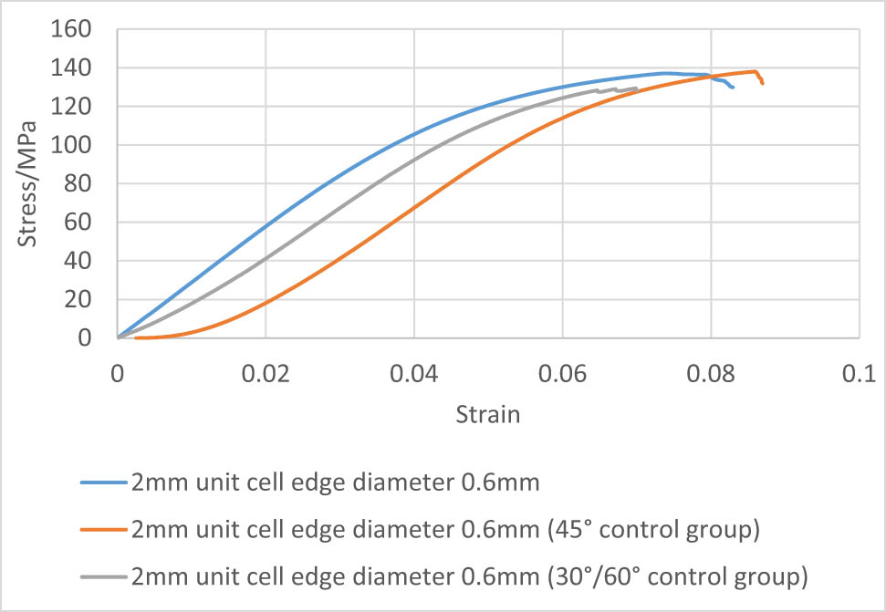
Stress–strain curves of 2 mm unit cell with 0.6 mm edge diameter samples at different angles.
By observing the slope of the stress–strain curve, it can be seen that the adjustment of the alignment direction of the regular octahedron has little effect on the compression test results. At the beginning of the 45° curve in Figure 22, it shows a horizontal segment. The probable reason for this phenomenon is that when the specimen is subjected to axial compression force, the maximum shear stress occurred at the 45° direction, which is identical to the angle between the layers. Therefore, the specimen exhibits higher deformation resistance against compression stress at the beginning. The equivalent elastic modulus of the sample with a 90° angle of 1.5 mm unit cell is approximately 2.13 GPa. The equivalent elastic modulus of the sample with a 45° angle is approximately 2.32 GPa. The equivalent elastic modulus of the 30°/60° angle specimen is about 1.98 GPa. Our calculation demonstrates that the difference between the equivalent elastic modulus of the 1.5 mm unit cell at different angles and the 90° direction does not exceed 10%. The equivalent elastic modulus of the 90° angle specimen of the 2 mm unit cell is about 2.92 GPa; The equivalent elastic modulus of the 45° angle specimen is about 2.63 GPa; The equivalent elastic modulus of the 30°/60° angle specimen is about 2.62 GPa. The percentage difference between the equivalent elastic modulus of the 90° specimen and different angles is around 11%.
By calculating the data and observing the stress curve, it can be seen that the compressive strength of specimen with the angle of 90° and the unit cell of 2 mm is 137.4 MPa, the compressive strength of the 45° angle specimen is 137.9 MPa, and the specimen with 30°/60° angle has a compressive strength of 129.3 MPa. The comparison shows that the difference in the compressive strength between the specimens at different angles and the specimen at 90° does not exceed 7%. The compressive strength of the 90° angle specimen of the 1.5 mm unit cell is 81.6 MPa, the compressive strength of the 45° angle specimen is 83.1 MPa, and the compressive strength of the 30°/60° angle specimen is 90.1 MPa. The difference in compressive strength of specimens with different angles and 90° specimens is within 10%. By analyzing the equivalent elastic modulus and compressive strength, comprehensively considering the influence of the error caused by the molding, it can be concluded that the variation in the octahedral arrangement angle has little effect on the overall performance of the structure. The regular octahedral structure is approximately isotropic in mechanical properties.
4 Discussion
In this article, starting from a basic unit of regular octahedron, ten groups of different parameter structures are designed according to the actual 3D printing standard parts parameters to make its macroscopic equivalent elastic modulus match the human bone. Compression tests simulation are carried out on the ten groups of models to verify the rationality of the structure. It is preliminarily verified that the equivalent elastic modulus increases with the increase in the edge diameter when the unit cell size is constant. We performed SLM molding of ten groups of models and observed the molding effect by SEM. The SEM results show that the SLM molding technology can realize the fabrication of long-range orderly arrangement of small and complex porous structures, ensuring the accuracy of complex structures molding. The surface roughness of the forming specimen increases with the increase in the diameter of the edges. The interpretation behind this phenomenon might be that the SLM processing adjusts the laser spot diameter and scanning rate in a small range according to the minimum molding size to ensure the molding accuracy. The specimens are subjected to compression test to reach the fracture limit. The stress–strain curve demonstrates that with a constant value of the unit cell size, the larger the edge diameter, the higher the value of the compressive strength, which is in line with the actual situation. By the adjustment of the micro-geometric dimensions, the equivalent elastic modulus of the SLM-formed specimens was controlled in the range of 2.18–3.83 GPa, while the modulus of a typical octahedral titanium alloy fabricated by EBM falls in a larger range of 0.912–64 GPa [47]. The comparison between the equivalent elastic modulus from the finite element calculations and the experimental test results shows that the simulation value is higher than the experimental one. The interpretation for this difference might be that the deposition process of SLM process leads to a local heterogeneity in the forming structure, while the finite element calculation is set to have homogeneous material properties. However, the transformation trends of the two are consistent, which is, the equivalent elastic modulus increases with the increase in the edge diameter.
The observation of the SEM molding effects in different directions exhibits that there is no obvious delamination in the positive Z-axis and positive Y-axis directions. It is preliminarily inferred that the molding structure is isotropic. The crossing section of the failure surface in the compression test shows a 45° angle to the pressure direction. The common sense of the mechanics of material is that the brittle materials fail to the normal stress, while the ductile materials fail to the shear stress. In addition, the direction of the maximum shear stress occurring is 45° to the direction of the axial force. It is inferred that the formed octahedral structure has certain flexibility and tend to fail to shear stress. The smooth fracture surface confirms the homogeneity of its mechanical properties. Two sets of parameters with quality molding structure are selected to perform the molding at two angles of 30°/60° and 45° to ensure that the compression direction remains unchanged, and the stress–strain curve is obtained. By calculating the equivalent elastic modulus and compressive strength results, we compared the mechanical properties with the specimen under normal angle molding (0°/90°), and the maximum deviation is no more than 11%. The identical mechanical properties verify the homogeneity and the isotropy of the regular octahedral unit structure. By comparison, the sheet and strut based porous Ti6Al4V scaffolds usually exhibit verified mechanical properties with respect to the orientation of external axial stress [48].
The current SLS melting still has its limitation and needs to be improved. The implant prosthesis for the human medical environment requires high resolution molding of complex surfaces. The surface roughness needs to be further reduced to improve the biocompatibility with biological tissues.
5 Conclusion
To solve the problem of stress shielding, ten groups of variable parameter porous structures are designed with regular octahedron as the basic unit. Finite element simulation is carried out to verify the rationality of the model. The simulation theoretical elastic modulus values are obtained. At the same time, the compression experiments are performed on ten groups of models. The actual value of the equivalent elastic modulus is compared with the simulated value. It can be concluded that the equivalent elastic modulus and the edge diameter change proportionally when the cell size is constant, and the error increases with the increase in the edge diameter. To ensure the molding accuracy, the SLM processing parameters can be improved. A smaller size porous structure is preferred for molding. The SLM process can realize the long-range orderly arrangement of the tiny complex porous structure, which is suitable for the fabrication of the clinical implant porous materials. We observed the molding effect through the fracture morphology, and compared the equivalent elastic modulus and compressive strength of different molding angles in the same compression direction. It shows that the mechanical properties and structure of the molded regular octahedron are approximately isotropic, which verifies the correctness of the theoretical calculations. Under the premise of ensuring that the elastic modulus of the implant meets the implantation requirements, the basic unit of a regular octahedron with a unit cell of 1.5 mm and an edge diameter of 0.4 mm is selected as the optimal implant structure geometry. The simulation and experimental data provided an effective reference for the design and molding of the implanted porous structure.
Acknowledgement
The research described here was supported by the General Program from the Educational Commission of Liaoning Province of China (Grant No. LJKZ0500 and LJKZ0475).
-
Funding information: The research described here was supported by the General Program from the Educational Commission of Liaoning Province of China (Grant No. LJKZ0500 and LJKZ0475).
-
Author contributions: Tianmin Guan and Yun Zhai conceived the presented idea. Yun Zhai and Sibo He wrote the manuscript. Sibo He carried out the experiments. Leilei performed the finite element analysis. All authors have discussed and agreed to the published version of the manuscript.
-
Conflict of interest: The authors declare that they have no known competing financial interests or personal relationships that could have appeared to influence the work reported in this article.
-
Data availability statement: The data used to support the findings of this study are available from the corresponding author upon request.
References
[1] Niinomi, M. Mechanical properties of biomedical titanium alloys. Materials Science and Engineering: A, Vol. 243, No. 1, 1998, pp. 231–236.10.1016/S0921-5093(97)00806-XSearch in Google Scholar
[2] Peighambardoust, N. S., A. A. Alamdari, U. Unal, and A. Motallebzadeh. In vitro biocompatibility evaluation of Ti1.5ZrTa0.5Nb0.5Hf0.5 refractory high-entropy alloy film for orthopedic implants: Microstructural, mechanical properties and corrosion behavior. Journal of Alloys and Compounds, Vol. 883, 2021, id. 160786.10.1016/j.jallcom.2021.160786Search in Google Scholar
[3] Lihuang, W., J. M. Liu Jiannan, H. Jing, and J. Xuejun. Preparation and biocompatibility of hierarchical porous strucrture on Ti alloys surface via integrated processes. Journal of Functional Materials, Vol. 52, No. 7, 2021, pp. 7024–7031.Search in Google Scholar
[4] Meijuanzhang, H. N., J. Zhongqiang, G. Fuhui, Q. Xiwang, and Z. Langping. Aeronautical cast Ti alloy and forming technology development. Journal of Aeronautical Materials, Vol. 36, No. 3, 2016, pp. 13–19.Search in Google Scholar
[5] Guo, Z. M. L. B. X., F. Yang, C. G. Chen, H. Y. Wang, and C. Zhang. Research progress in preparation technology of powder metallurgy titanium alloy. Powder Metallurgy Industry, Vol. 30, No. 176, 2020, pp. 6–12.Search in Google Scholar
[6] Liu, S. and Y. C. Shin. Additive manufacturing of Ti6Al4V alloy: A review. Materials & Design, Vol. 164, 2019, id. 107552.10.1016/j.matdes.2018.107552Search in Google Scholar
[7] Niinomi, M. and M. Nakai. Titanium-based biomaterials for preventing stress shielding between implant devices and bone. International Journal of Biomaterials, Vol. 2011, 2011, id. 836587.10.1155/2011/836587Search in Google Scholar PubMed PubMed Central
[8] Chang, J.-H., J.-F. Liu, Y.-S. Sun, C.-P. Wu, H.-H. Huang, and Y. Han. Mesoporous surface topography promotes bone cell differentiation on low elastic modulus Ti–25Nb–25Zr alloys for bone implant applications. Journal of Alloys and Compounds, Vol. 707, 2017, pp. 220–226.10.1016/j.jallcom.2016.12.206Search in Google Scholar
[9] Zadpoor, A. A. Mechanics of additively manufactured biomaterials. Journal of the Mechanical Behavior of Biomedical Materials, Vol. 70, 2017, pp. 1–6.10.1016/j.jmbbm.2017.03.018Search in Google Scholar PubMed
[10] Han, C., Y. Li, Q. Wang, S. Wen, Q. Wei, C. Yan, et al. Continuous functionally graded porous titanium scaffolds manufactured by selective laser melting for bone implants. Journal of the Mechanical Behavior of Biomedical Materials, Vol. 80, 2018, pp. 119–127.10.1016/j.jmbbm.2018.01.013Search in Google Scholar PubMed
[11] Song, Z. M., N. Chen, J. H. Liu, H. Tang, X. Deng, W. S. Xi, et al. Biological effect of food additive titanium dioxide nanoparticles on intestine: an in vitro study. Journal of Applied Toxicology, Vol. 35, No. 10, 2015, pp. 1169–1178.10.1002/jat.3171Search in Google Scholar PubMed
[12] Walschot, L. H., R. Aquarius, N. Verdonschot, P. Buma, and B. W. Schreurs. Porous titanium particles for acetabular reconstruction in total hip replacement show extensive bony armoring after 15 weeks. A loaded in vivo study in 10 goats. Acta Orthop, Vol. 85, No. 6, 2014, pp. 600–608.10.3109/17453674.2014.960660Search in Google Scholar PubMed PubMed Central
[13] Wehmöller, M., P. H. Warnke, C. Zilian, and H. Eufinger. Implant design and production – a new approach by selective laser melting. International Congress Series, Vol. 1281, 2005, pp. 690–695.10.1016/j.ics.2005.03.155Search in Google Scholar
[14] Thomann, U. I. and P. J. Uggowitzer. Wear–corrosion behavior of biocompatible austenitic stainless steels. Wear, Vol. 239, No. 1, 2000, pp. 48–58.10.1016/S0043-1648(99)00372-5Search in Google Scholar
[15] Long, M. and H. J. Rack. Titanium alloys in total joint replacement – a materials science perspective. Biomaterials, Vol. 19, No. 18, 1998, pp. 1621–1639.10.1016/S0142-9612(97)00146-4Search in Google Scholar
[16] Yang, K., H. P. Tang, J. Wang, G. Y. Yang, N. Liu, L. Jia, et al. Research progress on standardized and additive manufacturing of personalized porous tantalum implants. Hot Processing Technology, Vol. 46, No. 22, 2017, pp. 5–8.Search in Google Scholar
[17] Li, J. P., P. Habibovic, M. van den Doel, C. E. Wilson, J. R. de Wijn, C. A. van Blitterswijk, et al. Bone ingrowth in porous titanium implants produced by 3D fiber deposition. Biomaterials, Vol. 28, No. 18, 2007, pp. 2810–2820.10.1016/j.biomaterials.2007.02.020Search in Google Scholar PubMed
[18] Ziheng, Y. The personalized design and process research of selective laser melting manufacturing of Ti6Al4V tibial implant. Master’s Thesis, South China University of Technology, GuangZhou, 2014.Search in Google Scholar
[19] Wei, Z. Study on the structure design of porous dental implants based on SLM technology. Master’s Thesis, Zhejiang University of Technology, HangZhou, 2018.Search in Google Scholar
[20] Zhao Pei, J. P., X. Shu, Y. Yang, Z. Yan, and Q. Tao. A method for measuring the aperture of medical metallic porous structures based on rapid prototyping. Mechanical Research and Application, Vol. 30, No. 5, 2017, pp. 9–12.Search in Google Scholar
[21] Gibson, L. J. and M. F. Ashby. Cellular solids: Structure and properties, Cambridge University Press, Cambridge, 1997.10.1017/CBO9781139878326Search in Google Scholar
[22] Giorgio, I., M. Spagnuolo, U. Andreaus, D. Scerrato, and A. M. Bersani. In-depth gaze at the astonishing mechanical behavior of bone: A review for designing bio-inspired hierarchical metamaterials. Mathematics and Mechanics of Solids, Vol. 26, No. 7, 2021, pp. 1074–1103.10.1177/1081286520978516Search in Google Scholar
[23] Abali, B. E. and E. Barchiesi. Additive manufacturing introduced substructure and computational determination of metamaterials parameters by means of the asymptotic homogenization. Continuum Mechanics and Thermodynamics, Vol. 33, No. 4, 2021, pp. 993–1009.10.1007/s00161-020-00941-wSearch in Google Scholar
[24] Liu, R., Z. Song, W. Gao, and A. Luo. Analysis of octahedron unit structure of regular octahedron space deployable arm. Journal of Machine Design, Vol. 30, No. 6, 2013, pp. 72–75.Search in Google Scholar
[25] Wang, D., Y. Yang, R. Liu, D. Xiao, and J. Sun. Study on the designing rules and processability of porous structure based on selective laser melting (SLM). Journal of Materials Processing Technology, Vol. 213, No. 10, 2013, pp. 1734–1742.10.1016/j.jmatprotec.2013.05.001Search in Google Scholar
[26] Jetté, B., V. Brailovski, M. Dumas, C. Simoneau, and P. Terriault. Femoral stem incorporating a diamond cubic lattice structure: Design, manufacture and testing. Journal of the Mechanical Behavior of Biomedical Materials, Vol. 77, 2018, pp. 58–72.10.1016/j.jmbbm.2017.08.034Search in Google Scholar PubMed
[27] Meng, X. N. Finite element analysis and comparative study of biomechanical properties of 2052–2102 and Plus femoral prosthesis. Doctoral dissertation, Shandong University, Jinan, 2016.Search in Google Scholar
[28] Gibson, I. J. and M. F. Ashby. The mechanics of three-dimensional cellular materials. Proceedings of the Royal Society of London A Mathematical and Physical Sciences, Vol. 382, No. 1782, 1982, pp. 43–59.10.1098/rspa.1982.0088Search in Google Scholar
[29] Shao, Y. X., T. M. Guan, Y. Zhu, and X. Y. Chen. Research on key techniques of stress masking effect of implanted prosthesis. Journal of Shenzhen University (Science and Technology Edition), Vol. 38, No. 2, 2021, pp. 1–7.10.3724/SP.J.1249.2021.02201Search in Google Scholar
[30] Taniguchi, N., S. Fujibayashi, M. Takemoto, K. Sasaki, B. Otsuki, T. Nakamura, et al. Effect of pore size on bone ingrowth into porous titanium implants fabricated by additive manufacturing: An in vivo experiment. Materials Science and Engineering: C, Vol. 59, 2016, pp. 690–701.10.1016/j.msec.2015.10.069Search in Google Scholar PubMed
[31] Arabnejad, S., R. Burnett Johnston, J. A. Pura, B. Singh, M. Tanzer, and D. Pasini. High-strength porous biomaterials for bone replacement: A strategy to assess the interplay between cell morphology, mechanical properties, bone ingrowth and manufacturing constraints. Acta Biomater, Vol. 30, 2016, pp. 345–356.10.1016/j.actbio.2015.10.048Search in Google Scholar PubMed
[32] Hedayati, R., M. Sadighi, M. Mohammadi-Aghdam, and A. A. Zadpoor. Analytical relationships for the mechanical properties of additively manufactured porous biomaterials based on octahedral unit cells. Applied Mathematical Modelling, Vol. 46, 2017, pp. 408–422.10.1016/j.apm.2017.01.076Search in Google Scholar
[33] Wang, C. X. Study on design and fabrication technology of composite structure porous titanium alloy support. Master’s Thesis, Shanghai Jiao Tong University, Jinan, 2015.Search in Google Scholar
[34] Zhao, W. Y. Analysis of bone scaffold mechanics and permeability based on minimal curved surface. Doctoral dissertation, Dalian University of Technology, Dalian, 2019.Search in Google Scholar
[35] Dumas, M., P. Terriault, and V. Brailovski. Modelling and characterization of a porosity graded lattice structure for additively manufactured biomaterials. Materials & Design, Vol. 121, 2017, pp. 383–392.10.1016/j.matdes.2017.02.021Search in Google Scholar
[36] Onal, E., J. E. Frith, M. Jurg, X. Wu, and A. Molotnikov. Mechanical properties and in vitro behavior of additively manufactured and functionally graded Ti6Al4V porous scaffolds. Metals, Vol. 8, No. 4, 2018, id. 200.10.3390/met8040200Search in Google Scholar
[37] Amin Yavari, S., S. M. Ahmadi, R. Wauthle, B. Pouran, J. Schrooten, H. Weinans, et al. Relationship between unit cell type and porosity and the fatigue behavior of selective laser melted meta-biomaterials. Journal of the Mechanical Behavior of Biomedical Materials, Vol. 43, 2015, pp. 91–100.10.1016/j.jmbbm.2014.12.015Search in Google Scholar PubMed
[38] Zhang, B., X. Pei, C. Zhou, Y. Fan, Q. Jiang, A. Ronca, et al. The biomimetic design and 3D printing of customized mechanical properties porous Ti6Al4V scaffold for load-bearing bone reconstruction. Materials & Design, Vol. 152, 2018, pp. 30–39.10.1016/j.matdes.2018.04.065Search in Google Scholar
[39] Yao, X., S. K. Moon, B. Y. Lee, and G. Bi. Effects of heat treatment on microstructures and tensile properties of IN718/TiC nanocomposite fabricated by selective laser melting. International Journal of Precision Engineering and Manufacturing, Vol. 18, No. 12, 2017, pp. 1693–1701.10.1007/s12541-017-0197-ySearch in Google Scholar
[40] Wang, L., J. Kang, C. Sun, D. Li, Y. Cao, and Z. Jin. Mapping porous microstructures to yield desired mechanical properties for application in 3D printed bone scaffolds and orthopaedic implants. Materials & Design, Vol. 133, 2017, pp. 62–68.10.1016/j.matdes.2017.07.021Search in Google Scholar
[41] Suard, M., G. Martin, P. Lhuissier, R. Dendievel, F. Vignat, J. J. Blandin, et al. Mechanical equivalent diameter of single struts for the stiffness prediction of lattice structures produced by electron beam melting. Additive Manufacturing, Vol. 8, 2015, pp. 124–131.10.1016/j.addma.2015.10.002Search in Google Scholar
[42] Liang, H., Y. Yang, D. Xie, L. Li, N. Mao, C. Wang, et al. Trabecular-like Ti-6Al-4V scaffolds for orthopedic: fabrication by selective laser melting and in vitro biocompatibility. Journal of Materials Science & Technology, Vol. 35, No. 7, 2019, pp. 1284–1297.10.1016/j.jmst.2019.01.012Search in Google Scholar
[43] Dou, J. Research on 3D printing metal bone implant technology. Doctoral dissertation, Shenyang University of Aeronautics and Astronautics, Shenyang, 2018.Search in Google Scholar
[44] Wen, C. E., Y. Yamada, K. Shimojima, Y. Chino, T. Asahina, and M. Mabuchi. Processing and mechanical properties of autogenous titanium implant materials. Journal of Materials Science: Materials in Medicine, Vol. 13, No. 4, 2002, pp. 397–401.10.1023/A:1014344819558Search in Google Scholar
[45] He, J. K., D. C. Li, and B. H. Lu. Optimal design and manufacturing process of composite tibial half-joint structure. Journal of Xi’an Jiaotong University, Vol. 40, No. 5, 2006, pp. 563–567.Search in Google Scholar
[46] Yang, J. M., Y. Tang, H. Gu, Y. J. Liu, D. Z. Huang, and J. S. Chen. Research and application status of porous structures prepared by 3D printing. Materials Review, Vol. 32, No. 15, 2018, pp. 163–173.Search in Google Scholar
[47] de Formanoir, C., M. Suard, R. Dendievel, G. Martin, and S. Godet. Improving the mechanical efficiency of electron beam melted titanium lattice structures by chemical etching. Additive Manufacturing, Vol. 11, 2016, pp. 71–76.10.1016/j.addma.2016.05.001Search in Google Scholar
[48] Barber, H., C. N. Kelly, K. Nelson, and K. Gall. Compressive anisotropy of sheet and strut based porous Ti–6Al–4V scaffolds. Journal of the Mechanical Behavior of Biomedical Materials, Vol. 115, 2021, id. 104243.10.1016/j.jmbbm.2020.104243Search in Google Scholar PubMed
© 2021 Yun Zhai et al., published by De Gruyter
This work is licensed under the Creative Commons Attribution 4.0 International License.
Articles in the same Issue
- Review Articles
- A review on filler materials for brazing of carbon-carbon composites
- Nanotechnology-based materials as emerging trends for dental applications
- A review on allotropes of carbon and natural filler-reinforced thermomechanical properties of upgraded epoxy hybrid composite
- High-temperature tribological properties of diamond-like carbon films: A review
- A review of current physical techniques for dispersion of cellulose nanomaterials in polymer matrices
- Review on structural damage rehabilitation and performance assessment of asphalt pavements
- Recent development in graphene-reinforced aluminium matrix composite: A review
- Mechanical behaviour of precast prestressed reinforced concrete beam–column joints in elevated station platforms subjected to vertical cyclic loading
- Effect of polythiophene thickness on hybrid sensor sensitivity
- Investigation on the relationship between CT numbers and marble failure under different confining pressures
- Finite element analysis on the bond behavior of steel bar in salt–frost-damaged recycled coarse aggregate concrete
- From passive to active sorting in microfluidics: A review
- Research Articles
- Revealing grain coarsening and detwinning in bimodal Cu under tension
- Mesoporous silica nanoparticles functionalized with folic acid for targeted release Cis-Pt to glioblastoma cells
- Magnetic behavior of Fe-doped of multicomponent bismuth niobate pyrochlore
- Study of surfaces, produced with the use of granite and titanium, for applications with solar thermal collectors
- Magnetic moment centers in titanium dioxide photocatalysts loaded on reduced graphene oxide flakes
- Mechanical model and contact properties of double row slewing ball bearing for wind turbine
- Sandwich panel with in-plane honeycombs in different Poisson's ratio under low to medium impact loads
- Effects of load types and critical molar ratios on strength properties and geopolymerization mechanism
- Nanoparticles in enhancing microwave imaging and microwave Hyperthermia effect for liver cancer treatment
- FEM micromechanical modeling of nanocomposites with carbon nanotubes
- Effect of fiber breakage position on the mechanical performance of unidirectional carbon fiber/epoxy composites
- Removal of cadmium and lead from aqueous solutions using iron phosphate-modified pollen microspheres as adsorbents
- Load identification and fatigue evaluation via wind-induced attitude decoupling of railway catenary
- Residual compression property and response of honeycomb sandwich structures subjected to single and repeated quasi-static indentation
- Experimental and modeling investigations of the behaviors of syntactic foam sandwich panels with lattice webs under crushing loads
- Effect of storage time and temperature on dissolved state of cellulose in TBAH-based solvents and mechanical property of regenerated films
- Thermal analysis of postcured aramid fiber/epoxy composites
- The energy absorption behavior of novel composite sandwich structures reinforced with trapezoidal latticed webs
- Experimental study on square hollow stainless steel tube trusses with three joint types and different brace widths under vertical loads
- Thermally stimulated artificial muscles: Bio-inspired approach to reduce thermal deformation of ball screws based on inner-embedded CFRP
- Abnormal structure and properties of copper–silver bar billet by cold casting
- Dynamic characteristics of tailings dam with geotextile tubes under seismic load
- Study on impact resistance of composite rocket launcher
- Effects of TVSR process on the dimensional stability and residual stress of 7075 aluminum alloy parts
- Dynamics of a rotating hollow FGM beam in the temperature field
- Development and characterization of bioglass incorporated plasma electrolytic oxidation layer on titanium substrate for biomedical application
- Effect of laser-assisted ultrasonic vibration dressing parameters of a cubic boron nitride grinding wheel on grinding force, surface quality, and particle morphology
- Vibration characteristics analysis of composite floating rafts for marine structure based on modal superposition theory
- Trajectory planning of the nursing robot based on the center of gravity for aluminum alloy structure
- Effect of scan speed on grain and microstructural morphology for laser additive manufacturing of 304 stainless steel
- Influence of coupling effects on analytical solutions of functionally graded (FG) spherical shells of revolution
- Improving the precision of micro-EDM for blind holes in titanium alloy by fixed reference axial compensation
- Electrolytic production and characterization of nickel–rhenium alloy coatings
- DC magnetization of titania supported on reduced graphene oxide flakes
- Analytical bond behavior of cold drawn SMA crimped fibers considering embedded length and fiber wave depth
- Structural and hydrogen storage characterization of nanocrystalline magnesium synthesized by ECAP and catalyzed by different nanotube additives
- Mechanical property of octahedron Ti6Al4V fabricated by selective laser melting
- Physical analysis of TiO2 and bentonite nanocomposite as adsorbent materials
- The optimization of friction disc gear-shaping process aiming at residual stress and machining deformation
- Optimization of EI961 steel spheroidization process for subsequent use in additive manufacturing: Effect of plasma treatment on the properties of EI961 powder
- Effect of ultrasonic field on the microstructure and mechanical properties of sand-casting AlSi7Mg0.3 alloy
- Influence of different material parameters on nonlinear vibration of the cylindrical skeleton supported prestressed fabric composite membrane
- Investigations of polyamide nano-composites containing bentonite and organo-modified clays: Mechanical, thermal, structural and processing performances
- Conductive thermoplastic vulcanizates based on carbon black-filled bromo-isobutylene-isoprene rubber (BIIR)/polypropylene (PP)
- Effect of bonding time on the microstructure and mechanical properties of graphite/Cu-bonded joints
- Study on underwater vibro-acoustic characteristics of carbon/glass hybrid composite laminates
- A numerical study on the low-velocity impact behavior of the Twaron® fabric subjected to oblique impact
- Erratum
- Erratum to “Effect of PVA fiber on mechanical properties of fly ash-based geopolymer concrete”
- Topical Issue on Advances in Infrastructure or Construction Materials – Recycled Materials, Wood, and Concrete
- Structural performance of textile reinforced concrete sandwich panels under axial and transverse load
- An overview of bond behavior of recycled coarse aggregate concrete with steel bar
- Development of an innovative composite sandwich matting with GFRP facesheets and wood core
- Relationship between percolation mechanism and pore characteristics of recycled permeable bricks based on X-ray computed tomography
- Feasibility study of cement-stabilized materials using 100% mixed recycled aggregates from perspectives of mechanical properties and microstructure
- Effect of PVA fiber on mechanical properties of fly ash-based geopolymer concrete
- Research on nano-concrete-filled steel tubular columns with end plates after lateral impact
- Dynamic analysis of multilayer-reinforced concrete frame structures based on NewMark-β method
- Experimental study on mechanical properties and microstructures of steel fiber-reinforced fly ash-metakaolin geopolymer-recycled concrete
- Fractal characteristic of recycled aggregate and its influence on physical property of recycled aggregate concrete
- Properties of wood-based composites manufactured from densified beech wood in viscoelastic and plastic region of the force-deflection diagram (FDD)
- Durability of geopolymers and geopolymer concretes: A review
- Research progress on mechanical properties of geopolymer recycled aggregate concrete