Experimental and modeling investigations of the behaviors of syntactic foam sandwich panels with lattice webs under crushing loads
-
Zhilin Chen
 ,
Hota GangaRao
,
Hota GangaRao

Abstract
The composite sandwich structures with foam core and fiber-reinforced polymer skin are prone to damage under local impact. The mechanical behavior of sandwich panels (glass fiber-reinforced polymer [GFRP] skin reinforced with lattice webs and syntactic foams core) is studied under crushing load. The crushing behavior, failure modes, and energy absorption are correlated with the number of GFRP layers in facesheets and webs, fiber volume fractions of facesheets in both longitudinal and transverse directions, and density and thickness of syntactic foam. The test results revealed that increasing the number of FRP layers of lattice webs was an effective way to enhance the energy absorption of sandwich panels without remarkable increase in the peak load. Moreover, a three-dimensional finite-element (FE) model was developed to simulate the mechanical behavior of the syntactic foam sandwich panels, and the numerical results were compared with the experimental results. Then, the verified FE model was applied to conduct extensive parametric studies. Finally, based on experimental and numerical results, the optimal design of syntactic foam sandwich structures as energy absorption members was obtained. This study provides theoretical basis and design reference of a novel syntactic foam sandwich structure for applications in bridge decks, ship decks, carriages, airframes, wall panels, anticollision guard rails and bumpers, and railway sleepers.
Graphical abstract

1 Introduction
The composite sandwich structures, which are three-layered configurations composed of foam core and fiber-reinforced polymer skin, are prone to damage under local impact owing to their limited skin thicknesses and low core strengths [1,2,3]. Core materials with high strengths and stiffnesses are preferred in high-energy demand applications. Researchers have paid much attention on the mechanical performances of composite materials [4,5,6]. Syntactic foams consist of hollow spheres, which have low specific density and high hardness, embedded in a polymer matrix [7]. The hollow spheres may be composed of glass, carbon, ceramic, metal, and polymer-based materials, while polymer resins are used as binders [8,9]. The syntactic foams provide high compressive strengths, excellent damage tolerances, and energy absorption, which make them ideal core materials for composite sandwich structures [10]. However, the skin–core delamination is a major technical barrier to achieve full strength and energy absorption of sandwich composites [11]. Moreover, unresolved issues associated with the failure mechanism and crashworthiness of syntactic foam sandwich composites under crushing loads still exist. In this study, a novel syntactic foam sandwich structure with lattice webs is developed, which has the potential to enhance structural performance and energy absorption ability, hence the skin–core delamination can be improved. The crushing behavior of the syntactic foam sandwich panels is investigated to understand the mechanical properties and associated failure mechanisms. The resulting novel syntactic foam sandwich structures are expected to be lightweight, highly energy-dissipative, and corrosion resistant enabled for potential applications in bridge decks, ship decks, carriages, airframes, wall panels, anticollision guard rails and bumpers, and railway sleepers.
Comprehensive investigations on the mechanical properties of syntactic foams have been carried out [12]. Experimental studies have been carried out on the performances of syntactic foams under compressive [13,14], bending [8], tensile, dynamic, and thermal loads [15]. Lapčík et al. [16] have stated materials characterization of advanced fillers for composites engineering applications. Hu and Yu [15] have demonstrated that the addition of hollow polymer particles has led to high thermal stabilities of epoxy syntactic foams, while the tensile strength and modulus have decreased with the increase in particle volume fraction. However, glass-microballoon-S60-embedded epoxy syntactic foams have exhibited higher Young’s moduli when the microballoon volume fraction of the foam has been increased from 0.1 to 0.4. This is attributed to the microballoon S60 carrying major load. Pellegrino et al. [17] have studied the effect of the strain rate on the mechanical behaviors of syntactic polyurethane (PU) foams. The syntactic PU foams were extremely sensitive to the strain rate and have exhibited relatively high tensile and shear ductilities at both low and high strain rates. Gupta et al. [18] have compared the mechanical properties of syntactic foams composed of vinyl ester and epoxy matrices. The vinyl ester syntactic foam has exhibited a higher failure strain under compression than that of the epoxy-based syntactic foam. To fabricate lightweight syntactic foams with high strength, specially fabricated hollow silicate glass microspheres have been used by Yuan et al. [19]. Mechanical performances of syntactic foams were found to be improved significantly via surface modification of microspheres. Analytical and numerical models have also been developed to predict the linear elastic [20,21], nonlinear (considering the effect of matrix nonlinear behavior) [22], and thermal [23] properties of syntactic foams.
Although various studies have been carried out on the mechanical behaviors of syntactic foams and sandwich panels [24,25], no extensive studies have been carried out on syntactic foam sandwich composites. Papa and Rizzi [26] have investigated the mechanical properties of glass fiber-reinforced polymer (GFRP) sandwich panels filled with glass–epoxy microsphere syntactic foams with several glass composite plies in the skin interconnecting the skin and core. However, skin delamination was observed under bending and edgewise compressive loads. Similarly, Kumar and Ahmed [27] have fabricated phenolic syntactic foam core sandwich composites using resin-impregnated paper honeycomb (RIPH) to stiffen the core. The energy absorption capacity of the sandwich composite was 60% higher than that without RIPH. However, the incorporation of RIPH in the core led to the increase in the density of the core, because the open cell porosity of core material reduced significantly. Salleh et al. [28] have studied the mechanical properties of sandwich composites with GFRP skins and vinyl–ester–microballoon syntactic foam core. The compressive and tensile strengths as well as the compressive moduli of the sandwich composites have decreased with the increase in content of glass microballoons.
The emergence of the delamination failure has caused the limit of complementary and correlation of each component of sandwich structures [29]. Stitching and Z-pinning have been used to reduce the delamination of sandwich composites [30,31]. However, these techniques typically degrade the in-plane properties and cannot be simply used for structures with complex forms [32]. Karahan et al. [32] have focused on the quasi-static properties of GFRP sandwich panels with three-dimensional (3D) integrated fabric cores filled with PU foams. An increase in ply yarn length between the face sheets has led to compressive strength reduction. Thus, 3D integrated sandwich panels usually have limited thicknesses. Mitra and Raja [33] have inserted a premanufactured shear key in the grooves of the foam core. The in-plane compression capacities of their sandwich composite panels with semicircular shear keys (diameter: 8 mm) were approximately 25% higher than those without shear keys. Moreover, a novel lattice sandwich pattern exhibiting high compressive strength, stiffness capacities, and energy absorption has been reported [34,35,36].
Additional investigations on the mechanical properties of syntactic foams and sandwich composites have revealed that the lightweight core helps to increase the strengths and stiffnesses of FRPs and that syntactic foams have superior mechanical properties to those of conventional foams. The excellent properties of syntactic foam sandwiched composites have enabled the development of a load-bearing element with energy absorption capability [37]. However, unresolved issues associated with the failure mechanism and crashworthiness of syntactic foam sandwich composites under crushing loads still exist. The quasi-static crushing test is a cost-effective method [38] to provide a meaningful damage event regime under a low-velocity impact [37].
In this study, the mechanical behaviors of syntactic foam sandwich composite panels under quasi-static crushing loads are investigated. The test specimens are divided into three types: (1) syntactic foam panels, (2) GFRP–syntactic foam sandwich panels, and (3) GFRP–syntactic foam sandwich panels with lattice webs. The influences of the number of FRP skin layers, syntactic foam density, and lattice webs and their thickness are analyzed. Moreover, a 3D finite-element (FE) model is developed to conduct a parametric study, with a focus on optimal energy absorption and crushing load resistance.
2 Experimental methods
2.1 Materials
All GFRP–syntactic foam sandwich panels were manufactured by vacuum-assisted resin infusion. E-glass bidirectional woven fabrics and vinyl ester resin were used in facesheets and lattice webs. The fiber longitudinal and transverse volume fractions were 1:1 and 1:4 for the sheet faces, respectively. The volume fraction ratio for the fiber and resin was 1:1 for the lattice webs. The thickness of one layer of GFRP was approximately 0.6 mm, measured using flat coupons. To determine the material properties of the GFRP composites, tensile and compressive tests were carried out according to American Society for Testing and Materials ASTM D 638-14 [39] and ASTM D 695-15 [40], respectively. The measured properties of the composite materials are listed in Table 1.
Mechanical properties of GFRP
| Property | Fiber longitudinal–transversal volume fraction | |
|---|---|---|
| 1:1 (%) | 1:4 (%) | |
| Longitudinal tensile strength (MPa)/δ | 330.6/8.31 | 291.6/8.9 |
| Transverse tensile strength (MPa)/δ | 330.6/8.31 | 371.8/2.35 |
| Longitudinal tensile modulus of elasticity (GPa)/δ | 31.8/6.47 | 28.2/4.61 |
| Transverse tensile modulus of elasticity (GPa)/δ | 31.8/6.47 | 33.4/5.14 |
| Poisson’s ratio/δ | 0.22/4.35 | 0.15/8.01 |
Note: δ is the coefficient of variation.
Macrosphere syntactic foams, supplied by Engineered Syntactic Systems, USA, with densities of 450 and 480 kg/m3 were used in this study. The volume fraction of spheres of the foam was 58%. The average sphere diameters of the foams with densities of 450 and 480 kg/m3 were 4.04 and 4.12 mm, while the average wall thicknesses were 0.122 and 0.150 mm, respectively. For each density, five square coupons were tested according to ASTM D 1621-16 [41] to obtain the compressive strength and modulus. Table 2 presents the measured properties of the syntactic foams.
Mechanical properties of syntactic foams
| Foam density (kg/m3) | Compressive strength (MPa)/δ (%) | Young’s modulus (GPa)/δ (%) |
|---|---|---|
| 450 | 22.12/3.70 | 1.00/5.16 |
| 480 | 25.01/3.30 | 2.18/2.00 |
Note: δ is the coefficient of variation.
2.2 Test specimen
Sixteen specimens were fabricated to study the quasi-static crushing responses, including two synthetic foam panels, eight GFRP–synthetic foam sandwich panels without webs, and six GFRP–synthetic foam sandwich panels with lattice webs (Figure 1). The distance between the webs was 75 mm. All test specimens had the same width (300 mm) and length (300 mm). The differences between the test specimens were the number of layers of FRP facesheets and cross webs, fiber volume fraction of FRP facesheets, and densities and heights of the syntactic foams. The sixteen specimens are denoted as Sd30, SD30, F44d30, F44D30, F41d30, F21D30, F41D30, F61D30, F41D25, F41D35, F41D30w2, F41D30w4, F41D30w6, F41d30w4, F41D25w4, and F41D35w4. Table 3 lists the characteristics of the test specimens.
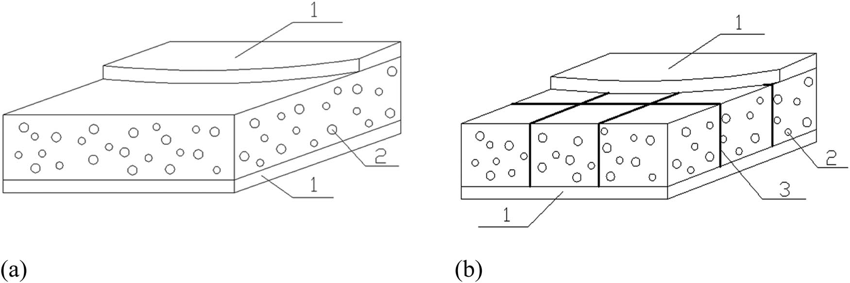
Diagram of syntactic foam sandwich panels (1. GFRP sheet faces, 2. Syntactic foam core, 3. Lattice webs). (a) Sandwiches with GFRP sheet faces. (b) Sandwiches with GFRP skins and lattice webs.
Characteristics of the test specimens
| Specimen | Number of fiber layers of FRP facesheets | Fiber longitudinal–transversal volume fraction | Density of the syntactic foam (kg/m3) | Thickness of the foam core (mm) | Number of fiber layers of webs |
|---|---|---|---|---|---|
| Sd30 | — | — | 450 | 30 | — |
| SD30 | — | — | 480 | 30 | — |
| F44d30 | 4 | 1:4 | 450 | 30 | — |
| F44D30 | 4 | 1:4 | 480 | 30 | — |
| F41d30 | 4 | 1:1 | 450 | 30 | — |
| F21D30 | 2 | 1:1 | 480 | 30 | — |
| F41D30 | 4 | 1:1 | 480 | 30 | — |
| F61D30 | 6 | 1:1 | 480 | 30 | — |
| F41D25 | 4 | 1:1 | 480 | 25 | — |
| F41D35 | 4 | 1:1 | 480 | 35 | — |
| F41D30w2 | 4 | 1:1 | 480 | 30 | 2 |
| F41D30w4 | 4 | 1:1 | 480 | 30 | 4 |
| F41D30w6 | 4 | 1:1 | 480 | 30 | 6 |
| F41d30w4 | 4 | 1:1 | 450 | 30 | 4 |
| F41D25w4 | 4 | 1:1 | 480 | 25 | 4 |
| F41D35w4 | 4 | 1:1 | 480 | 35 | 4 |
Note: In the first column, the first letter, S or F, represents the bare syntactic foam panel or FRP-syntactic foam sandwich panel, respectively; the second letter, d or D, represents the density of the syntactic foam, 450 or 480 kg/m3, respectively; the third letter w represents the distance between the webs of 75 mm; the first number after F represents the number of fiber layers of FRP facesheets; the second number after F represents the fiber transversal–longitudinal volume fraction; the two numbers after d or D represent the thickness of the foam core of 25, 30, and 35 mm; and the last number represents the number of fiber layers of webs.
2.3 Experimental setup
The crush strengths of all specimens were evaluated using a universal testing machine with a capacity of 200 kN. The specimens were fixed between two steel plates with a square hole with a width of 200 mm in the center. The steel plates were fixed on two steel I-beams by screws. The specimens were indented by a hemispherical-end steel head with a mass of 1.5 kg and a diameter of 20 mm. The indentation loading was controlled by displacement at a rate of 5 mm/min [42]. During the testing, the load was recorded by a load cell above the indenter and a linear variable-displacement transducer was mounted centrally under the specimen to record the displacement. The time interval for data collection of the load and displacement was 5 s. The test setup, measurement, and fixture systems are shown in Figure 2.

Test setup and fixture system (unit: mm). (a) Test setup. (b) Side view of fixture system. (c) Vertical view of fixture system.
3 Results and discussion
The damage propagation and failure modes are identified using the test specimens. Subsequently, load–displacement curves and analysis of energy absorptions and variations in experimental data as functions of the number of FRP layers of facesheets and lattice webs are presented. Our analysis also pertains to the fiber transverse–longitudinal volume fraction and syntactic foam density and thickness.
3.1 Failure modes
Figure 3 shows the test specimens after the quasi-static crushing. In the bare syntactic foam panels, a small dent with a diameter of 20 mm was observed at the load location; the indenter completely penetrated the panel, as shown in Figure 3(a). A crack was formed on the front surface of the syntactic foam panel, which then propagated in the 45° direction owing to the shear failure of the syntactic foam. On the rear surface of the syntactic foam panel, the damage region was wider than that on the front surface, and four diagonal radial cracks were observed upon the increase in applied load.

Damage of typical specimens. (a) Bare syntactic foam panels (i.e., SD30). (b) FRP–syntactic foam sandwich panels (i.e., F41D30). (c) FRP–syntactic foam sandwich panels with lattice webs (i.e., F41D30w4).
In the FRP–syntactic foam sandwich panels, a hole with a diameter of 20 mm was observed on the front surface accompanied by the breakage of the fiber and resin around the loading location. The penetration area on the rear surface was considerably smaller than that on the front surface. In addition, a circular delamination zone with a diameter of approximately 90 mm was observed on the rear surface. The side view of the cross section shows that the debonding between the rear face and foam and shear failure of the foam core dominantly determined the failure modes (Figure 3(b)).
The damages on the front surfaces of the sandwich specimens with lattice webs were similar to those of the specimens without lattice webs. However, the delamination zone on the rear surface of the specimen with lattice webs had a diamond shape because the debonding between the rear face and foam was controlled by the lattice webs. The debonding was further confirmed by the photograph of the cross section in Figure 3(c), which reveals the breakages of the fiber and resin on both front and rear faces, including the shear deformation of the foam core.
3.2 Load–displacement curves
Typical load–displacement curves of the bare syntactic foam panels and FRP–syntactic foam sandwich panels are shown in Figure 4. The load on the synthetic foam panels increased linearly to approximately half of its peak, and several small peaks were generated before the maximum load owing to particle fracture. Brittle failure occurred in the syntactic foam panels after the maximum loads were reached.

Typical load–displacement curves. (a) Bare syntactic foam panels. (b) FRP–syntactic foam sandwich panels.
All sandwich panels exhibited four-phase displacement responses: linear-elastic phase, plastic phase, foam compaction phase, and bottom facesheet penetration phase. The load on the sandwich panels increased to its peak in the linear-elastic phase, decreased by approximately 60–70%, and then fluctuated around a sustained load. The penetration of the top facesheets led to a sharp decrease in load. The plastic phase is associated with the crushing of the foam core, propagations of cracks in the matrix of foams, and breakage and delamination of the GFRP bottom facesheets, which led to continuous energy dissipation. Further deformation led to the compaction of the foam core associated with the crushing of macrospheres and extrusion of foam blocks.
In the foam compaction phase, the vertical displacement increased with the applied load, and then extrusion of the foam occurred. Subsequently, the bottom facesheets were penetrated by the load indenter, which led to load reduction.
The energy absorption capacity E is calculated using the classical relation:
where P is the applied load, Δ corresponds to the displacement history, and Δ st corresponds to the displacement at the start of the foam compaction phase.
Figure 5 shows the influences of the number of FRP layers of facesheets on the peak load P max and stiffness in linear-elastic phase K 1 of the specimens (SD30, F21D30, F41D30, and F61D30) with the same fiber volume fractions in both transverse and longitudinal directions and foam densities. For the specimens with the foam density of 480 kg/m3, when the number of layers of GFRP facesheets was increased from 0 to 6, P max and K 1 increased by ∼48 to 143% and 27 to 222%, respectively. Increasing the number of FRP layers contributes to hinder the propagation of crushing damage in the laminates, leading to enhance the crushing resistance of sandwich composite panels. The E values of the specimens with four and six layers of GFRP facesheets increased by 17 and 26%, respectively, compared to that of the specimen with two layers of GFRP facesheets (Table 4). However, the increase in number of GFRP layers of facesheets from two to six did not increase the specific energy absorption (SEA = energy absorption per unit mass) of the sandwich panel.

Effect of the number of FRP layers on facesheets.
Summary of test matrix and results
| Specimen | m (g) | P max (kN) | K 1 (kN/mm) | E (J) | SEA (J/kg) |
|---|---|---|---|---|---|
| Sd30 | 540 | 9.5 | 4.32 | — | — |
| SD30 | 576 | 11.5 | 4.74 | — | — |
| F44d30 | 886 | 16.4 | 8.46 | 119 | 134 |
| F44D30 | 922 | 18.1 | 8.70 | 141 | 153 |
| F41d30 | 882 | 19.6 | 9.90 | 154 | 175 |
| F21D30 | 747 | 17.0 | 6.03 | 129 | 173 |
| F41D30 | 918 | 21.4 | 9.95 | 151 | 165 |
| F61D30 | 1,089 | 27.9 | 15.26 | 190 | 175 |
| F41D25 | 822 | 22.0 | 8.93 | 147 | 179 |
| F41D35 | 1,014 | 23.8 | 13.34 | 168 | 166 |
| F41D30w2 | 955 | 21.7 | 10.02 | 166 | 174 |
| F41D30w4 | 992 | 24.5 | 10.14 | 173 | 174 |
| F41D30w6 | 1,028 | 26.5 | 10.27 | 213 | 207 |
| F41d30w4 | 957 | 22.6 | 9.99 | 148 | 155 |
| F41D25w4 | 883 | 23.4 | 9.09 | 142 | 161 |
| F41D35w4 | 1,100 | 24.3 | 13.42 | 184 | 167 |
Figure 6 shows the influences of the fiber transverse–longitudinal volume fraction on the P max and K 1 values of the specimens (F41d30, F44d30, F41D30, and F44D30) with the same number of GFRP layers. P max and K 1 of F41d30 were 20 and 17% higher than those of F44d30, while P max and K 1 of F41D30 were 18 and 14% higher than those of F44D30, respectively. E and SEA of F41d30 were ∼30% higher than those of F44d30, while E and SEA of F41D30 were ∼8% higher than those of F44D30. The higher fiber volume fraction in both transverse and longitudinal directions of the facesheets led to lower peak load, stiffness, and energy absorption. This is attributed to the lower bond force transfer between fibers.
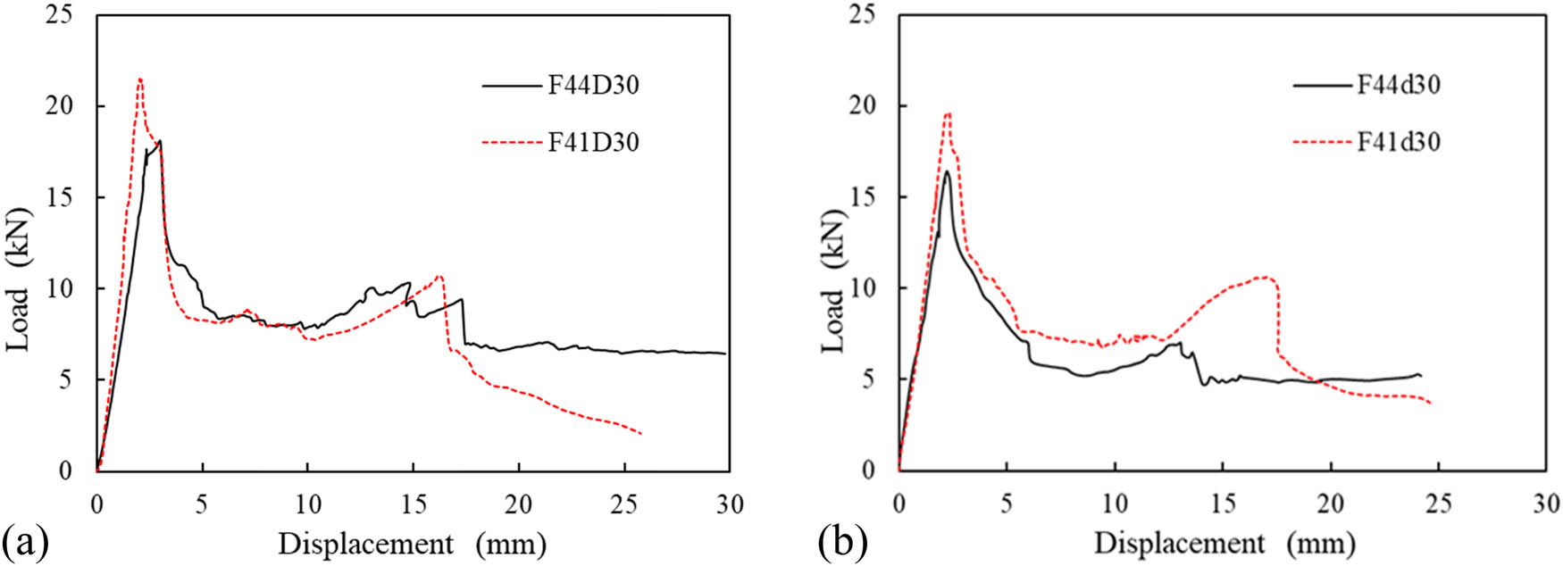
Effect of fiber transverse–longitudinal volume fraction. (a) Specimens with foam density 480 kg/m3. (b) Specimens with foam density 450 kg/m3.
Figure 7 shows the influences of the syntactic foam density on the P max and K 1 values of typical specimens (Sd30, SD30, F41d30, F41D30, F41d30w4, and F41D30w4). The increase in syntactic foam density from 450 to 480 kg/m3 led to increases in P max and K 1 of the bare syntactic foam panel of 21 and 10%, respectively. This is because the syntactic foam with density of 480 kg/m3 has smaller sphere diameter and higher wall thickness of spheres than those of syntactic foam with density of 450 kg/m3. The syntactic foam density had small influences on P max and K 1 of the sandwich panel. For the specimens without webs, the increase in foam density from 450 to 480 kg/m3 led to small decreases in E and SEA owing to the larger plastic deformation in the specimen with the lower foam density. However, the increase in foam density increased E and SEA of the specimen with lattice webs owing to the larger load resistance at the higher foam density. The energy absorption is related to the load and deformation of the specimen. Specimens with higher load-carrying capacities and larger plastic deformations usually have higher energy-absorption abilities. In a specimen with a lower density of the foam core, the syntactic foam has more hollow spheres. The crushing of spheres contributes to a better energy absorption and increases the deformation. However, the syntactic foam with a lower density has a lower load-carrying capacity. The structure of the sandwiches also plays an important role in the energy absorption. The lattice webs can significantly improve the debonding characteristics of the sandwich panel, which increases the load-carrying capacity. Hence, the specimens with lattice webs and higher foam density had higher energy-absorption capabilities.
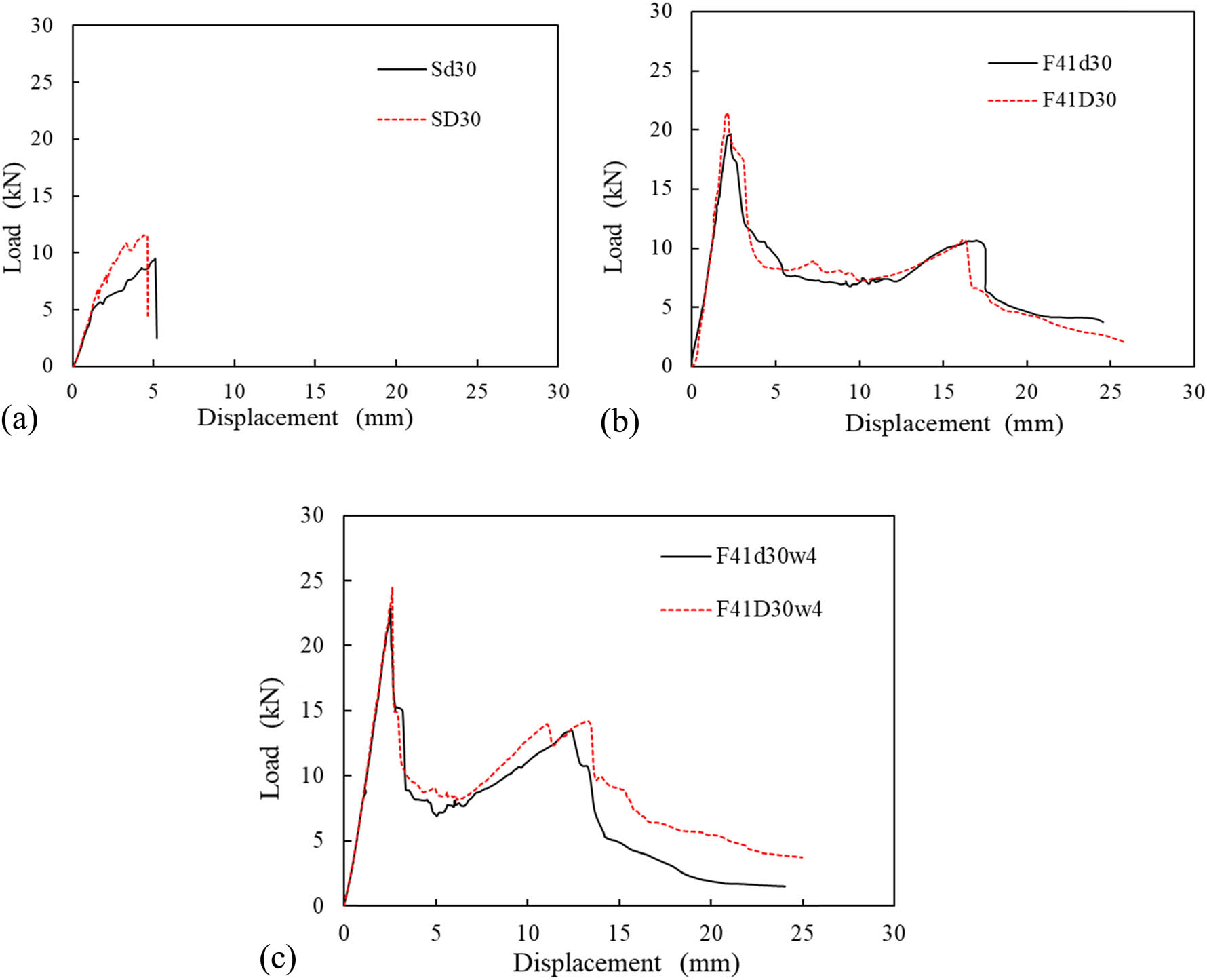
Effect of foam density. (a) Bare syntactic foam panels. (b) Sandwich specimens. (c) Sandwich specimens with lattice webs.
Figure 8 shows the influences of the thickness of the foam core on the P max and K 1 values of typical sandwich specimens with and without lattice webs (F41D25, F41D30, F41D35, F41D25w4, F41D30w4, and F41D35w4). When the thickness of the foam core was increased from 25 to 35 mm, P max and K 1 increased by 8 and 49% for the sandwich specimens without lattice webs and by 4 and 48% for the sandwich specimens with lattice webs, respectively. The thickness of the foam core did not considerably affect the peak load of the sandwich specimens but considerably increased the stiffness. As the thickness of syntactic foam core increases, the thickness of the syntactic sandwich panel increases, which leads to greatly increased moment of inertia and hence an increase in stiffness. Although the sandwich specimens with thicker foam cores could absorb higher amounts of energy, their SEAs did not significantly change.

Effect of the thickness of the foam core. (a) Sandwich specimens without lattice webs. (b) Sandwich specimens with lattice webs.
Figure 9 shows the influences of the layer number of lattice webs on the P max and K 1 values of typical specimens (F41D30, F41D30w2, F41D30w4, and F41D30w6). When the number of layers in the lattice webs was increased from 0 to 6, P max and K 1 increased by 24 and 3%, while E and SEA increased by 41 and 26%, respectively. It reveals that the lattice webs play an important role in energy absorption in consort with the core. This indicates that the layer number of lattice webs influenced the peak load more significantly than the stiffness. Therefore, the increase in number of FRP layers of lattice webs is an effective approach to increase the energy absorption.
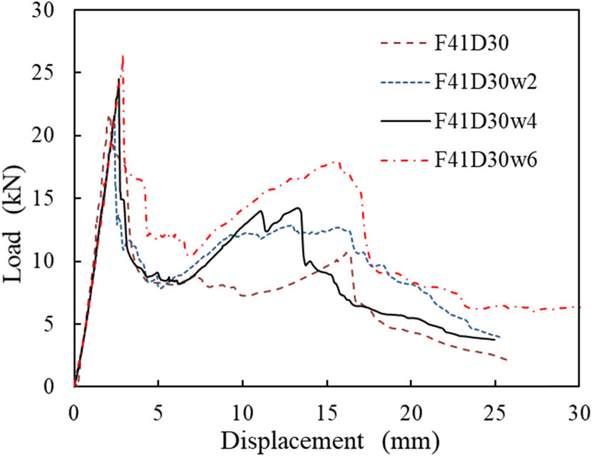
Effect of the number of FRP web layers.
4 FE simulation
A 3D FE model was developed using Abaqus Explicit 2019. The numerical results were compared to those obtained experimentally. The verified FE model was used to analyze the effects of the loading position, distance between lattice webs, and number of layers of FRP facesheets of the sandwich panels with webs.
4.1 Material models
The material properties of both GFRP and syntactic foam were obtained using coupon test results. The GFRP facesheets and webs were assumed to exhibit linear elastic behaviors. The input elastic properties for GFRP are listed in Table 5. The Hashin damage criterion was used to predict the failure of the GFRP. Alhijazi et al. [43] have reviewed the FE analysis of fiber composites, in which the Hashin damage criterion was mentioned that it has the smallest error compared to experimental data. The Hashin damage criterion consists of four different damage initiation criteria: fiber tension, fiber compression, matrix tension, and matrix compression. The fracture energy was defined as the area under the stress–strain curves obtained from the mechanical tests in FRP coupons according to standards ASTM D695-15 [40] and ASTM D2344/D2344M-16 [44]. The Hashin damage criterion in Abaqus is used alongside a progressive damage variable, which computes the damage state at each increment based on the stress state and the fracture energy for each failure mode. Therefore, four different fracture energy parameters should be defined in Abaqus model. The fracture energy parameters were obtained from ref. [45], as listed in Table 6. The material properties of the syntactic foam were included in the elastic–plastic model, in which the plasticity modulus was set to 50% of the elastic modulus. The indenter was composed of a high-strength steel and thus was modeled as a rigid object with a density of 7,800 kg/m3 and modulus of 210 GPa.
Elastic properties of GFRP
| Properties | Fiber longitudinal–transversal volume fraction | ||
|---|---|---|---|
| 1:1 | 1:4 | ||
| Tensile strength | S t,1 (MPa) | 330.6 | 291.6 |
| S t,2 (MPa) | 330.6 | 371.8 | |
| Compressive strength | S c,1 (MPa) | 201 | 161 |
| S c,2 (MPa) | 201 | 201 | |
| Young’s modulus | E x (GPa) | 31.8 | 28.2 |
| E y (GPa) | 31.8 | 33.4 | |
| E z (GPa) | 9.4 | 9.4 | |
| Poisson’s ratio | ν xy | 0.22 | 0.15 |
| ν xz | 0.22 | 0.15 | |
| ν yz | 0.22 | 0.15 | |
| Shear strength | S 12 (MPa) | 30.6 | 30.6 |
| S 23 (MPa) | 30.6 | 30.6 | |
| Shear modulus | G xy (GPa) | 3.8 | 4.1 |
| G xz (GPa) | 13.0 | 14.5 | |
| G yz (GPa) | 13.0 | 12.3 | |
Fracture energies of GFRP used for simulations [45]
| G ft (N/mm) | G fc (N/mm) | G mt (N/mm) | G mc (N/mm) |
|---|---|---|---|
| 2.38 | 5.28 | 0.424 | 0.948 |
Note: G ft and G fc are the longitudinal tensile and compressive fracture energies of GFRP sheets, respectively, and G mt and G mc are the transverse tensile and compressive fracture energies of GFRP sheets, respectively.
4.2 FE model construction
SC8R, an 8-node continuum shell element with reduced integration and three integration points across each layer’s thickness, was used to model the GFRP facesheets and webs, and C3D8R, an 8-node linear brick reduced-integration hourglass control element, was used to model the foam core and steel indenter. The mesh size is taken as 5 mm because further decrease in element size almost generates the same results while the computational time increases remarkably. In the numerical model, the loading speed of the steel indenter is taken as 5 mm/min. The four edges of the sandwich panels were clamped. Surface-to-surface contact elements were used to simulate the interface between the steel indenter and sandwich panel, as well as the GFRP and foam core. This type of contact considers slip and separation. Hence, slip/debonding is displayed if either occurs between the GFRP surface and foam surface. Bursi and Jaspart [46] have investigated the influence of the friction coefficient on the plate connection response. Their simulated results indicate that the friction coefficient in the range of 0–0.5 had a rather limited effect on the connection response. Hence, the friction coefficient was set to 0.1 for the contact surface of the GFRP and foam core.
4.3 Comparison of simulated and experimental results
The simulated and selected experimental load–displacement curves of the syntactic foam sandwich panels are shown in Figure 10. The simulated curves in Figure 10 show that the model provided a reasonable trend with respect to the test data, i.e., the FE analysis could describe the overall shapes of the measured load–displacement curves. Table 7 reveals that the simulated peak loads and stiffnesses are in good agreement with the experimental values. Most of the simulated stiffnesses are slightly larger than the test results. In the FE model, the four edges of the sandwich panels were assumed to be clamped, while the real boundary conditions of test specimens were not ideally clamped. Such variation is attributed to the simulated model, which is stiffer than the actual test specimens.

Comparison of simulated and experimental load–displacement curves. (a) F41D25, (b) F41D30, (c) F61D30, (d) F41D30w2, (e) F41D30w4, (f) F41D25w4.
Comparison of the initial peak load and stiffness between simulated and experimental results
| Specimen | Tested peak load P max (kN) | Simulated peak load
|
|
Tested stiffness K 1 (kN/mm) | Simulated stiffness
|
|
|---|---|---|---|---|---|---|
| F41D25 | 22.0 | 22.8 | 3.6% | 8.93 | 9.67 | 8.3% |
| F41D30 | 21.4 | 23.4 | 9.4% | 9.95 | 10.41 | 4.6% |
| F61D30 | 27.9 | 28.3 | 1.4% | 15.26 | 13.73 | −10.1% |
| F41D30w2 | 21.7 | 22.7 | 4.6% | 10.02 | 10.69 | 6.7% |
| F41D30w4 | 24.5 | 24.2 | −1.2% | 10.14 | 11.02 | 8.7% |
| F41D25w4 | 23.4 | 22.7 | −3.0% | 9.09 | 9.82 | 8.1% |
The damage modes of the simulated F41D30 and F41D30w2 are shown in Figure 11. The maximum von Mises stress of F41D30 was observed at the center of the foam core. On the rear surface of F41D31, the von Mises stress reached high levels at the center of the facesheets and gradually decreased along the radial direction, thereby leading to the crush of the foam core and debonding of the rear facesheets and foam core. The maximum von Mises stress of F41D30w2 was observed at the bottom facesheets. The rear surface of F41D30w2 exhibited a diamond shape of the von Mises stress contour in the center region, which indicates that the debonding of the foam core and rear face was controlled by the lattice webs.

Stress contour at the peak load (unit: MPa). (a) Cross section of F41D30. (b) Rear surface of F41D30. (c) Cross section of F41D30w2. (d) Rear surface of F41D30w2. (e) Numerical progress of F41D30w2. (f) Experimental progress of F41D30w2.
4.4 Parametric studies
4.4.1 Influence of the loading position
The loading positions of all test specimens were at the center of the front surface. The verified FE models were used to investigate the responses of the sandwich panels when the loads were applied on the middle of a web, as shown in Figure 12(a). The simulated results indicate that the loading position had an insignificant influence on the stiffness of the sandwich panel (F41D30w2 and F41D30w4), as shown in Figure 12(b) and (c). Compared to F41D30w2 and F41D30w4 under the loads applied on the center of the front surface, the initial peak load increased by 7 and 14% for F41D30w2 and F41D30w4 under the loads applied on the web, respectively, as the local stiffness of the lattice FRP webs was higher than that of the syntactic foam core.

Influence of varied parameters on the load–displacement curves. Note: In the specimen name, I means the load is applied on the web; and 50, 75, and 100 mean the distance of webs are 50, 75, and 100 mm, respectively. (a) Simulated loading position. (b) Influence of loading position of F41D30w2. (c) Influence of loading position of F41D30w4. (d) Influence of distance of webs. (e) Influence of layers of facesheets of specimens with webs.
4.4.2 Influence of the distance between lattice webs
Three different distances between lattice webs (l 0 = 50, 75, and 100 mm) in F41D30w4 were investigated. Figure 12(d) shows the load–displacement curves of the F41D30w4 samples with different distances between lattice webs. When l 0 was above 75 mm, it had insignificant influences on the initial peak load and stiffness. The decrease in l 0 from 75 to 50 mm led to an increase in initial peak load of 7% and increase in stiffness of 14%.
4.4.3 Influence of the layer number of facesheets on the sandwich panels with webs
The influence of the layer number of facesheets on the sandwich panel without webs was experimentally investigated. In addition, the influence of the layer number of facesheets on the sandwich panels with webs was investigated by the verified FE models. Three different numbers of layers of facesheets (2, 4, and 6) were investigated for the specimens with lattice webs. Figure 12(e) shows the load–displacement curves of the specimens with lattice webs and different layers of facesheets. When the layer number was increased from 2 to 4 and 6, the initial peak load increased by 25 and 64%, while the stiffness increased by 78 and 142%, respectively. The test and simulated results indicate that the increase in layer number of facesheets is an effective approach to increase the load-carrying capacity of the sandwich panel with or without webs.
4.4.4 Recommended optimal structure
The simulated results of the specimens with different distances of lattice webs and layer numbers of facesheets of the sandwich panels with lattice webs were listed in Table 8. Based on the experimental and numerical SEA results in Tables 4 and 8, the syntactic foam sandwich panel with six layers of facesheets and webs, fiber transverse–longitudinal volume fraction of 1:1, syntactic foam density of 480 kg/m3, thickness of foam core of 25 mm, and distance between lattice webs of 50 mm had the maximum SEA.
Summary of simulated matrix and results
| Specimen | m (g) | P max (kN) | K 1 (kN/mm) | E (J) | SEA (J/kg) |
|---|---|---|---|---|---|
| F41D30w4-50 | 992 | 25.9 | 12.58 | 216 | 217.7 |
| F41D30w4-100 | 992 | 22.3 | 10.88 | 144 | 145.2 |
| F21D30w4 | 821 | 19.4 | 8.94 | 107 | 130.3 |
| F61D30w4 | 1,163 | 31.9 | 19.58 | 306 | 263.1 |
5 Conclusion
A novel GFRP–syntactic foam sandwich panel with lattice webs, which has the potential to enhance structural performance and energy absorption ability, was developed. The crushing behaviors and energy absorptions of the composite sandwich panels were investigated. Moreover, an optimal design of the syntactic foam sandwich structures as energy absorption members was recommended. The results obtained in this study can be summarized as follows.
The bare syntactic foam panels exhibited shear-dominated failures and were pierced by the indenter. The GFRP–syntactic foam sandwich panels without webs exhibited shear failures of the foam cores accompanied by the delamination of facesheets and core. Notably, the lattice webs increased the debonding strength between the facesheets and foam.
The peak load and stiffness of the sandwich panel considerably increased with the number of layers of GFRP facesheets, whereas the energy absorption nominally increased. The sandwich specimens with thicker foam cores exhibited higher stiffnesses and energy absorption abilities almost without change in SEA, whereas the syntactic foam density did not considerably affect the peak load and stiffness of sandwich panels. The increase in the number of FRP layers of lattice webs was an effective approach to increase the energy absorption of the sandwich panel without considerable increase in peak load, assuming the absence of premature debonding.
The verified FE model was used to conduct a parameter study. The numerical results of verified FE model indicated that the loads applied on the web led to a slight increase in initial peak load in sandwich panels compared to the loads applied at the center of the panel. The decrease in distance between lattice webs from 75 to 50 mm led to slight increases in initial peak load and stiffness. The increase in the layer number of facesheets on the sandwich panels with webs led to considerable increases in the initial peak load and stiffness.
Based on experimental and numerical results, the optimal design of syntactic foam sandwich structures as energy absorption members was obtained. The structure with six layers of facesheets and webs, fiber transverse–longitudinal volume fraction of 1:1, syntactic foam density of 480 kg/m3, thickness of foam core of 25 mm, and distance between lattice webs of 50 mm had the maximum SEA.
-
Funding information: This study was financially supported by the National Natural Science Foundation of China (Grant 51578283) and Top Six Talent Projects in Jiangsu Province, China (Grant No. JZ-024). H. GangaRao and R. Liang acknowledge the support by US-NSF.
-
Author contribution: Z. Chen: Formal analysis, validation, writing – original draft. Y. Zhang: Formal analysis, validation. J. Wang: Investigation, conceptualization, formal analysis, resources, project administration. H. GangaRao: Writing – review & editing, methodology. R. Liang: Formal analysis. Y. Zhang: Performing the experiments. D. Hui: Visualization.
-
Conflict of interest: One of the co-authors of this paper (Prof. David Hui) is an Editor in Chief of Reviews on Advanced Materials Science.
-
Data availability statement: The raw data required to reproduce these findings are available for download from http://dx.doi.org/10.17632/9yrs4v4gsr.3#file-265de9f7-2cf2-4dd6-a79b-7d5082d56c6b. The processed data required to reproduce these findings are available for download from http://dx.doi.org/10.17632/9yrs4v4gsr.3#file-1ae0bba6-3496-4c80-8aaa-7a2516d6008c.
References
[1] Kulpa, M., T. Siwowski, M. Rajchel, and L. Wlasak. Design and experimental verification of a novel fibre-reinforced polymer sandwich decking system for bridge application. Journal of Sandwich Structures and Materials, Vol. 5, 2020, id. 371.10.1177/1099636220909756Search in Google Scholar
[2] Hayman, B. and A. T. Echtermeyer. Reduction of strength of GFRP sandwich panels in naval ships by face sheet holes, cracks and impact damage. Journal of Sandwich Structures and Materials, Vol. 21, No. 5, 2019, pp. 1621–1653.10.1177/1099636219836357Search in Google Scholar
[3] Yuan, C. Crushing responses and design of CF/EP composite structures. Doctoral dissertation, University of Sydney, Sydney, 2018.Search in Google Scholar
[4] Sahmani, S. and B. Safaei. Large-amplitude oscillations of composite conical nanoshells with in-plane heterogeneity including surface stress effect. Applied Mathematical Modelling, Vol. 89, 2021, pp. 1792–1813.10.1016/j.apm.2020.08.039Search in Google Scholar
[5] Moradi-Dastjerdi, R., K. Behdinan, B. Safaei, and Z. Qin. Buckling behavior of porous CNT-reinforced plates integrated between active piezoelectric layers. Engineering Structures, Vol. 222, 2020, id. 111141.10.1016/j.engstruct.2020.111141Search in Google Scholar
[6] Safaei, B., R. Moradi-Dastjerdi, Z. Qin, K. Behdinan, and F. Chu. Determination of thermoelastic stress wave propagation in nanocomposite sandwich plates reinforced by clusters of carbon nanotubes. Journal of Sandwich Structures & Materials, 2019, pp. 1–22.10.1177/1099636219848282Search in Google Scholar
[7] Nakonieczny, D. S., M. Antonowicz, and Z. K. Paszenda. Cenospheres and their application advantages in biomedical engineering – a systematic review. Reviews on Advanced Materials Science, Vol. 59, 2020, pp. 115–130.10.1515/rams-2020-0011Search in Google Scholar
[8] Rizzi, E., E. Papa, and A. Corigliano. Mechanical behavior of a syntactic foam: Experiments and modelling. International Journal of Solids and Structures, Vol. 37, No. 40, 2000, pp. 5773–5794.10.1016/S0020-7683(99)00264-4Search in Google Scholar
[9] Huang, Y. J. Fiber-reinforced syntactic foams. Doctoral dissertation, University of Southern California, Los Angeles, 2009.Search in Google Scholar
[10] Gupta, N. and S. Sankaran. On the characterisation of syntactic foam core sandwich composites for compressive properties. Journal of Reinforced Plastics and Composites, Vol. 18, No. 14, 1999, pp. 1347–1357.10.1177/073168449901801406Search in Google Scholar
[11] Zhang, Y., W. Liu, C. Yin, Y. Ma, and L. Wang. Mode II interfacial fracture characterization of foam core sandwich materials at elevated temperatures: The effects of frictional stresses between the crack edges. International Journal of Solids and Structures, Vol. 193–194, 2020, pp. 28–38.10.1016/j.ijsolstr.2020.02.001Search in Google Scholar
[12] Afolabi, L. O., Z. M. Ariff, S. F. S. Hashim, T. Alomayri, S. Mahzan, K.-A. Kamarudin, et al. Syntactic foams formulations, production techniques, and industry applications: A review. Journal of Materials Research and Technology, Vol. 9, No. 5, 2020, pp. 10698–10718.10.1016/j.jmrt.2020.07.074Search in Google Scholar
[13] Huang, R. and P. Li. Elastic behaviour and failure mechanism in epoxy syntactic foams: The effect of glass microballoon volume fractions. Composites Part B: Engineering, Vol. 78, 2015, pp. 401–408.10.1016/j.compositesb.2015.04.002Search in Google Scholar
[14] Ghosh, D., A. Wiest, and R. D. Conner. Uniaxial quasistatic and dynamic compressive response of foams made from hollow glass microspheres. Journal of the European Ceramic Society, Vol. 36, No. 3, 2016, pp. 781–789.10.1016/j.jeurceramsoc.2015.10.018Search in Google Scholar
[15] Hu, G. and D. Yu. Tensile, thermal and dynamic mechanical properties of hollow polymer particle-filled epoxy syntactic foam. Materials Science and Engineering: A, Vol. 528, No. 15, 2011, pp. 5177–5183.10.1016/j.msea.2011.03.071Search in Google Scholar
[16] Lapčík, L., M. Vašina, B. Lapčíková, D. Hui, E. Otyepková, R. W. Greenwood, et al. Materials characterization of advanced fillers for composites engineering applications. Nanotechnology Reviews, Vol. 8, 2019, pp. 503–512.10.1515/ntrev-2019-0045Search in Google Scholar
[17] Pellegrino, A., V. L. Tagarielli, R. Gerlach, and N. Petrinic. The mechanical response of a syntactic polyurethane foam at low and high rates of strain. International Journal of Impact Engineering, Vol. 75, 2015, pp. 214–221.10.1016/j.ijimpeng.2014.08.005Search in Google Scholar
[18] Gupta, N., R. Ye, and M. Porfiri. Comparison of tensile and compressive characteristics of vinyl ester/glass microballoon syntactic foams. Composites Part B: Engineering, Vol. 41, No. 3, 2010, pp. 236–245.10.1016/j.compositesb.2009.07.004Search in Google Scholar
[19] Yuan, J., Z. An, and J. Zhang. Effects of hollow microsphere surface property on the mechanical performance of high strength syntactic foams. Composites Science & Technology, Vol. 199, 2020, id. 108309.10.1016/j.compscitech.2020.108309Search in Google Scholar
[20] Marur, P. R. Numerical estimation of effective elastic moduli of syntactic foams. Finite Elements in Analysis and Design, Vol. 46, No. 11, 2010, pp. 1001–1007.10.1016/j.finel.2010.07.006Search in Google Scholar
[21] Yu, M., P. Zhu, and Y. Ma. Global sensitivity analysis for the elastic properties of hollow spheres filled syntactic foams using high dimensional model representation method. Computational Materials Science, Vol. 61, 2012, pp. 89–98.10.1016/j.commatsci.2012.04.005Search in Google Scholar
[22] Panteghini, A. and L. Bardella. On the compressive strength of glass microballoons-based syntactic foams. Mechanics of Materials, Vol. 82, 2015, pp. 63–77.10.1016/j.mechmat.2014.12.005Search in Google Scholar
[23] Zeltmann, S. E., B. Chen, and N. Gupta. Thermal expansion and dynamic mechanical analysis of epoxy matrix–borosilicate glass hollow particle syntactic foams. Journal of Cellular Plastics, Vol. 54, No. 3, 2018, pp. 463–481.10.1177/0021955X17691566Search in Google Scholar
[24] Moradi-Dastjerdi, R., K. Behdinan, B. Safaei, and Z. Qin. Static performance of agglomerated CNT-reinforced porous plates bonded with piezoceramic faces. International Journal of Mechanical Sciences, Vol. 188, 2020, id. 105966.10.1016/j.ijmecsci.2020.105966Search in Google Scholar
[25] Safaei, B. The effect of embedding a porous core on the free vibration behavior of laminated composite plates. Steel and Composite Structures, Vol. 35, No. 5, 2020, pp. 659–670.Search in Google Scholar
[26] Papa, E. and E. Rizzi. Mechanical behaviour of a syntactic foam/glass fibre composite sandwich: Experimental results. Structural Engineering and Mechanics, Vol. 12, No. 2, 2001, pp. 169–188.10.12989/sem.2001.12.2.169Search in Google Scholar
[27] Kumar, S. A. and K. S. Ahmed. Compression behavior and energy absorption capacity of stiffened syntactic foam core sandwich composites. Journal of Reinforced Plastics and Composites, Vol. 32, No. 18, 2013, pp. 1370–1379.10.1177/0731684413492867Search in Google Scholar
[28] Salleh, Z., M. M. Islam, J. A. Epaarachchi, and H. Su. Mechanical properties of sandwich composite made of syntactic foam core and GFRP skins. AIMS Materials Science, Vol. 3, No. 4, 2016, pp. 1704–1727.10.3934/matersci.2016.4.1704Search in Google Scholar
[29] Zhang, H., C. Gao, H. Li, F. Pang, T. Zou, H. Wang, et al. Analysis of functionally graded carbon nanotube-reinforced composite structures: A review. Nanotechnology Reviews, Vol. 9, 2020, pp. 1408–1426.10.1515/ntrev-2020-0110Search in Google Scholar
[30] Potluri, P., E. Kusak, and T. Reddy. Novel stitch-bonded sandwich composite structures. Composite Structures, Vol. 59, 2003, pp. 251–259.10.1016/S0263-8223(02)00087-9Search in Google Scholar
[31] Mines, R. A. W., C. M. Worrall, and A. G. Gibson. Low velocity perforation behaviour of polymer composite sandwich panels. International Journal of Impact Engineering, Vol. 21, No. 10, 1998, pp. 855–879.10.1016/S0734-743X(98)00037-2Search in Google Scholar
[32] Karahan, M., N. Karahan, H. Gul, and J. Ivens. Quasi-static behavior of three-dimensional integrated core sandwich composites under compression loading. Journal of Reinforced Plastics and Composites, Vol. 32, No. 5, 2013, pp. 289–299.10.1177/0731684412471091Search in Google Scholar
[33] Mitra, N. and B. R. Raja. Improving delamination resistance capacity of sandwich composite columns with initial face/core debond. Composites Part B: Engineering, Vol. 43, 2012, pp. 1604–1612.10.1016/j.compositesb.2011.11.039Search in Google Scholar
[34] Wang, B., G. Zhang, S. Wang, L. Ma, and L. Wu. High velocity impact response of composite lattice core sandwich structures. Applied Composite Materials, Vol. 21, 2014, pp. 377–389.10.1007/s10443-013-9345-4Search in Google Scholar
[35] Li, B., Y. Liu, and K. Tan. A novel meta-lattice sandwich structure for dynamic load mitigation. Journal of Sandwich Structures & Materials, Vol. 21, No. 6, 2019, pp. 1880–1905.10.1177/1099636217727144Search in Google Scholar
[36] Bai, X., Z. Zheng, and A. Nakayama. Heat transfer performance analysis on lattice core sandwich panel structures. International Journal of Heat & Mass Transfer, Vol. 143, 2019, id. 118525.10.1016/j.ijheatmasstransfer.2019.118525Search in Google Scholar
[37] Wang, J., H. GangaRao, M. Li, R. Liang, and W. Liu. Axial behavior of columns with glass fiber-reinforced polymer composite shells and syntactic foam core. Journal of Composites for Construction, Vol. 23, No. 2, 2019, id. 04018083.10.1061/(ASCE)CC.1943-5614.0000926Search in Google Scholar
[38] Wagih, A., P. Maimí, N. Blanco, and J. Costa. A quasi-static indentation test to elucidate the sequence of damage events in low velocity impacts on composite laminates. Composites Part A: Applied Science and Manufacturing, Vol. 82, 2016, pp. 180–189.10.1016/j.compositesa.2015.11.041Search in Google Scholar
[39] ASTM International. ASTM D638 Standard test method for tensile properties of plastics, ASTM International, West Conshohocken, PA, USA, 2014.Search in Google Scholar
[40] ASTM International. ASTM D695 Standard test method for compressive properties of rigid plastics, ASTM International, West Conshohocken, PA, USA, 2015.Search in Google Scholar
[41] ASTM International. ASTM D1621 Standard test method for compressive properties of rigid cellular plastics, ASTM International, West Conshohocken, PA, USA, 2016.Search in Google Scholar
[42] Othman, A., S. Abdullah, A. K. Ariffin, and N. A. N. Mohamed. Investigating the quasi-static axial crushing behavior of polymeric foam-filled composite pultrusion square tubes. Materials and Design, Vol. 63, 2014, pp. 446–459.10.1016/j.matdes.2014.06.020Search in Google Scholar
[43] Alhijazi, M., Q. Zeeshan, Z. Qin, B. Safaei, and M. Asmael. Finite element analysis of natural fibers composites: A review. Nanotechnology Reviews, Vol. 9, 2020, pp. 853–875.10.1515/ntrev-2020-0069Search in Google Scholar
[44] ASTM International. ASTM D2344/D2344M Standard test method for short-beam strength of polymer matrix composite materials and their laminates, ASTM International, West Conshohocken, PA, USA, 2016.Search in Google Scholar
[45] Nunes, F., J. R. Correia, and N. Silvestre. Structural behavior of hybrid FRP pultruded beams: Experimental, numerical and analytical studies. Thin-Walled Structures, Vol. 106, 2016, pp. 201–217.10.1016/j.tws.2016.05.004Search in Google Scholar
[46] Bursi, O. S. and J. P. Jaspart. Basic issues in the finite element simulation of extended end plate connections. Computers & Structures, Vol. 69, 1998, pp. 361–382.10.1016/S0045-7949(98)00136-9Search in Google Scholar
© 2021 Zhilin Chen et al., published by De Gruyter
This work is licensed under the Creative Commons Attribution 4.0 International License.
Articles in the same Issue
- Review Articles
- A review on filler materials for brazing of carbon-carbon composites
- Nanotechnology-based materials as emerging trends for dental applications
- A review on allotropes of carbon and natural filler-reinforced thermomechanical properties of upgraded epoxy hybrid composite
- High-temperature tribological properties of diamond-like carbon films: A review
- A review of current physical techniques for dispersion of cellulose nanomaterials in polymer matrices
- Review on structural damage rehabilitation and performance assessment of asphalt pavements
- Recent development in graphene-reinforced aluminium matrix composite: A review
- Mechanical behaviour of precast prestressed reinforced concrete beam–column joints in elevated station platforms subjected to vertical cyclic loading
- Effect of polythiophene thickness on hybrid sensor sensitivity
- Investigation on the relationship between CT numbers and marble failure under different confining pressures
- Finite element analysis on the bond behavior of steel bar in salt–frost-damaged recycled coarse aggregate concrete
- From passive to active sorting in microfluidics: A review
- Research Articles
- Revealing grain coarsening and detwinning in bimodal Cu under tension
- Mesoporous silica nanoparticles functionalized with folic acid for targeted release Cis-Pt to glioblastoma cells
- Magnetic behavior of Fe-doped of multicomponent bismuth niobate pyrochlore
- Study of surfaces, produced with the use of granite and titanium, for applications with solar thermal collectors
- Magnetic moment centers in titanium dioxide photocatalysts loaded on reduced graphene oxide flakes
- Mechanical model and contact properties of double row slewing ball bearing for wind turbine
- Sandwich panel with in-plane honeycombs in different Poisson's ratio under low to medium impact loads
- Effects of load types and critical molar ratios on strength properties and geopolymerization mechanism
- Nanoparticles in enhancing microwave imaging and microwave Hyperthermia effect for liver cancer treatment
- FEM micromechanical modeling of nanocomposites with carbon nanotubes
- Effect of fiber breakage position on the mechanical performance of unidirectional carbon fiber/epoxy composites
- Removal of cadmium and lead from aqueous solutions using iron phosphate-modified pollen microspheres as adsorbents
- Load identification and fatigue evaluation via wind-induced attitude decoupling of railway catenary
- Residual compression property and response of honeycomb sandwich structures subjected to single and repeated quasi-static indentation
- Experimental and modeling investigations of the behaviors of syntactic foam sandwich panels with lattice webs under crushing loads
- Effect of storage time and temperature on dissolved state of cellulose in TBAH-based solvents and mechanical property of regenerated films
- Thermal analysis of postcured aramid fiber/epoxy composites
- The energy absorption behavior of novel composite sandwich structures reinforced with trapezoidal latticed webs
- Experimental study on square hollow stainless steel tube trusses with three joint types and different brace widths under vertical loads
- Thermally stimulated artificial muscles: Bio-inspired approach to reduce thermal deformation of ball screws based on inner-embedded CFRP
- Abnormal structure and properties of copper–silver bar billet by cold casting
- Dynamic characteristics of tailings dam with geotextile tubes under seismic load
- Study on impact resistance of composite rocket launcher
- Effects of TVSR process on the dimensional stability and residual stress of 7075 aluminum alloy parts
- Dynamics of a rotating hollow FGM beam in the temperature field
- Development and characterization of bioglass incorporated plasma electrolytic oxidation layer on titanium substrate for biomedical application
- Effect of laser-assisted ultrasonic vibration dressing parameters of a cubic boron nitride grinding wheel on grinding force, surface quality, and particle morphology
- Vibration characteristics analysis of composite floating rafts for marine structure based on modal superposition theory
- Trajectory planning of the nursing robot based on the center of gravity for aluminum alloy structure
- Effect of scan speed on grain and microstructural morphology for laser additive manufacturing of 304 stainless steel
- Influence of coupling effects on analytical solutions of functionally graded (FG) spherical shells of revolution
- Improving the precision of micro-EDM for blind holes in titanium alloy by fixed reference axial compensation
- Electrolytic production and characterization of nickel–rhenium alloy coatings
- DC magnetization of titania supported on reduced graphene oxide flakes
- Analytical bond behavior of cold drawn SMA crimped fibers considering embedded length and fiber wave depth
- Structural and hydrogen storage characterization of nanocrystalline magnesium synthesized by ECAP and catalyzed by different nanotube additives
- Mechanical property of octahedron Ti6Al4V fabricated by selective laser melting
- Physical analysis of TiO2 and bentonite nanocomposite as adsorbent materials
- The optimization of friction disc gear-shaping process aiming at residual stress and machining deformation
- Optimization of EI961 steel spheroidization process for subsequent use in additive manufacturing: Effect of plasma treatment on the properties of EI961 powder
- Effect of ultrasonic field on the microstructure and mechanical properties of sand-casting AlSi7Mg0.3 alloy
- Influence of different material parameters on nonlinear vibration of the cylindrical skeleton supported prestressed fabric composite membrane
- Investigations of polyamide nano-composites containing bentonite and organo-modified clays: Mechanical, thermal, structural and processing performances
- Conductive thermoplastic vulcanizates based on carbon black-filled bromo-isobutylene-isoprene rubber (BIIR)/polypropylene (PP)
- Effect of bonding time on the microstructure and mechanical properties of graphite/Cu-bonded joints
- Study on underwater vibro-acoustic characteristics of carbon/glass hybrid composite laminates
- A numerical study on the low-velocity impact behavior of the Twaron® fabric subjected to oblique impact
- Erratum
- Erratum to “Effect of PVA fiber on mechanical properties of fly ash-based geopolymer concrete”
- Topical Issue on Advances in Infrastructure or Construction Materials – Recycled Materials, Wood, and Concrete
- Structural performance of textile reinforced concrete sandwich panels under axial and transverse load
- An overview of bond behavior of recycled coarse aggregate concrete with steel bar
- Development of an innovative composite sandwich matting with GFRP facesheets and wood core
- Relationship between percolation mechanism and pore characteristics of recycled permeable bricks based on X-ray computed tomography
- Feasibility study of cement-stabilized materials using 100% mixed recycled aggregates from perspectives of mechanical properties and microstructure
- Effect of PVA fiber on mechanical properties of fly ash-based geopolymer concrete
- Research on nano-concrete-filled steel tubular columns with end plates after lateral impact
- Dynamic analysis of multilayer-reinforced concrete frame structures based on NewMark-β method
- Experimental study on mechanical properties and microstructures of steel fiber-reinforced fly ash-metakaolin geopolymer-recycled concrete
- Fractal characteristic of recycled aggregate and its influence on physical property of recycled aggregate concrete
- Properties of wood-based composites manufactured from densified beech wood in viscoelastic and plastic region of the force-deflection diagram (FDD)
- Durability of geopolymers and geopolymer concretes: A review
- Research progress on mechanical properties of geopolymer recycled aggregate concrete