Solar photovoltaic-integrated energy storage system with a power electronic interface for operating a brushless DC drive-coupled agricultural load
-
Varjana Hemant Kumar
 ,
Ramnarayan Patel
,
Ramnarayan Patel

Abstract
This article describes the design and construction of a solar photovoltaic (SPV)-integrated energy storage system with a power electronics interface (PEI) for operating a Brushless DC (BLDC) drive coupled to agricultural loads. The proposed system is intended to make use of the electrical power available at under-utilized, pre-installed solar pumps used for irrigation. The PEI allows efficient energy management by charging and discharging depending on available solar power. The BLDC drive is a high-performance motor drive that requires a smooth and stable DC voltage. The bidirectional DC converter provides this while also allowing for efficient energy management between the battery and the solar PV system. The simulation results illustrate that the system is capable of efficiently managing energy between the battery and solar panels, providing a stable DC voltage to drive the BLDC motor. In addition to this, the results demonstrate the feasibility of integrating a solar system with a battery and BDC for driving BLDC in various agricultural applications. The experimental findings validate the simulation outcomes for the proposed setup implemented in pre-installed, untapped SPV systems. The system is able to provide a stable and efficient power source while also allowing for efficient energy management and utilization of solar energy.
1 Introduction
The rapidly rising demand for energy is one of the most significant challenges and causes of worry in the modern era. This is because of the rapid depletion of fossil resources as well as the negative effects that this has on the environment. Apart from this, the NOAA National Centers for Environmental Information published an article on climate change and global temperature that evidences the Earth's average temperature is increasing due to human activities, due to which the year 2022 was recorded as the sixth warmest year on record between the periods 1880–2022, N.D. 2024. Scientists and researchers could use this overheating phenomenon to harvest clean and green energy from the sun. As a consequence of this, there is a rising trend towards the use of renewable energy sources (RES) in a wide range of applications. Solar photovoltaic (SPV) is a better alternative than other RES options due to a number of features, including its affordability, modularity, ease of installation, and ability to integrate with existing power grid environment (Majewski et al. 2021, Kishor et al. 2023). First, with the proper interfacing of power electronics-based DC–DC converters, it is feasible to achieve both effective integration and optimal power extraction from solar PV systems. The performance of the solar panels is weather-dependent. Solar panels require direct sunlight to operate at their maximum efficiency, and cloudy days can reduce the amount of energy that can be generated. In solar PV systems, however, converters face significant issues of high failure rates due to the power semiconductors and passive components that are involved in their fabrication (Alagu et al. 2021, Raj et al. 2020). During the last couple of decades, the use and application of SPV have seen substantial increases in developing India.
The photovoltaic (PV) business in India has grown tremendously in recent years, pushed up both by government incentives and growing consumer demand for green power (Raghavendra et al. 2019). It is crucial to know, evaluate, and perceive the technological R&D, industrial planning, rules and regulations, power pricing guidelines, and project enticement initiatives in order to meet the requirements of the rapidly expanding PV power market in India (Rauf et al. 2023). Subsidies, tax breaks, and low-interest loans are just some of the policies and incentives put in place by governments to spur PV industry growth. As a consequence, new advances in the business in India allow both those on rooftops and those used in large-scale utilities to increase (Behuria 2020).
More than three million solar pumps have been installed in India; most of them are used for irrigation because diesel and electric irrigation pumps in India consume a lot of fossil fuel energy. They emit 45 million tones of CO2 a year, accounting for 8–12% of greenhouse gas emissions. The Indian government has unveiled a solar pumping scheme for agriculture and drinking water to build 0.1 million Solar Photovoltaic Water Pumps (SPVWP) in 2014–2015 and 1 million by 2020–2021 (Shukla et al. 2018, Kumar et al. 2023). The Indian government has been promoting the use of solar-powered irrigation pumps as a means of increasing agricultural productivity and reducing dependence on traditional grid-tied electrical systems (Thakur et al. 2022).
Solar PV pumping is gaining popularity in Chhattisgarh, as it is rich in solar resources, and the government has launched a number of incentives to promote the farmer for agricultural and rural development. As of 2022, the state has installed 2,432 solar irrigation pumps and 71,753 solar agricultural pumps through the PM KUSUM solar pump yojana and the Saur Sujana Yojana Scheme in Chhattisgarh. And by 2030, more than 1.17 million solar irrigation pumps of three and five horsepower will be installed all through the state, bringing about a revolutionary transformation in the agricultural sector (Rathore et al. 2018, Suman 2018, Khare et al. 2020).
The pre-installed solar PV systems provide land that could enhance the productivity and revenue of farmers in investors in agriculture, where crops can be grown beneath or alongside these sites (Kumbhaj et al. 2018). These agrivoltaics are beneficial to conventional farmers, clean energy producers, and policymakers should consider adopting stilt-mounted PV systems, particularly in areas where land resources are relatively scarce (Giri and Mohanty 2022, Pearce 2021). Agrivoltaics has enhanced economic growth by entering industrial clusters. The research shows that rural areas with high yearly power usage and an economic ripple impact of gross production are targeted (Sekiyama and Nagashima 2019, Nakata and Ogata 2023, Kishor and Patel 2022a).
The innumerable solar-energized agricultural systems, including solar water pumps, solar desalination systems, solar dryers, solar heat pump systems, and process heat generation through solar concentrator systems, are intended to boost crop yields and guarantee the agricultural sector's success. However, the technological advancements and combination of various approaches to solar systems in agricultural sectors would be a better choice for obtaining a better yield, which leads to the sustainable development of the agricultural sector. The available solar PV power is not being utilized to its maximum potential; the mentioned works describe its use to drive BLDC only for pumping, as they have BLDC motors are highly efficient, typically ranging from 85 to 95%, which means they use less power and generate less heat than traditional motors (Agostini et al. 2021, Shchur et al. 2021, Giri and Mohanty 2022, Kumar and Singh 2019, 2018). In addition to the above, it is well suited for in-home appliances or medical equipment as they operate quietly and the noise level is very low.
In summary, while solar water pumping systems offer several advantages, there are also some disadvantages to consider, including high initial cost, weather dependence, maintenance requirements, water quality issues, and limited pumping capacity. These challenges need to be carefully evaluated to determine whether a solar water pumping system is the right solution for a specific application. The size of the solar panel and the battery both have a limit on the pumping power of solar water pumping systems. This can make it challenging to pump large volumes of water or to pump water over long distances.
The primary emphasis in solar pumping research and development is not placed on assessing water demands. As a result, the currently installed SPV pumps are operating at only 50% of their full capacity. By optimizing the size of solar panels, it is possible to mitigate the carbon footprint to a particular extent by reducing farmers' reliance on the grid with the use of solar pumps. Hence, the utilization of untapped solar energy, paired with a battery-based energy storage system (ESS), presents an opportunity to address the gap in work by powering agricultural loads at farms. The installation of SPV pumps is typically carried out in areas with limited or no access to the electrical grid. In grid-isolated villages, the agri-loads primarily rely on diesel-operated generators for operation.
In order to cope with the aforementioned challenge, a dual-stage PV-powered system has been implemented. This system includes an integrated battery storage unit, which is used to power the brushless DC (BLDC) motor drive. The implemented structure maintains a constant DC link voltage and is accountable for operating the agricultural loads that are connected to it. This setup effectively reduces the carbon footprint when compared to using diesel prime movers, especially during periods when the solar pumping action is not being utilized. The main focus of this work is to integrate battery-based storage system with converters that effectively capture and utilize the untapped energy of pre-installed solar pumps when they are not avidly pumping. The utilization of off-grid dual power converters unveils a viable alternative to the familiar use of diesel engines by farmers for powering agricultural loads, thereby facilitating a reduction in carbon footprints.
Looking into the above-mentioned data and works, the proposed work focuses on the utilization of untapped energy while not using pre-installed solar PV systems. The work aims to drive the mechanical units coupled to BLDC-driven solar PV-integrated battery-based storage systems to increase the farmer's reliability and economic status by reducing grid dependency for processing their farm crops. Further, the system consists of a solar PV system with a DC–DC boost conversion stage to maintain a 48-volt DC link voltage, to which a battery bank is connected parallelly by means of a bidirectional DC–DC converter to maintain constant DC link voltage whenever power outages occur by PV generators. One of the major outcomes is that whenever the BLDC-driven mechanical loads are processed, the process cannot be intermitted because of input constraints on PV generators for supplying power to maintain DC voltage for operation. This system can used where more power shedding or less connectivity to the grid or to grid-independent remote areas, increasing the employability status of those areas.
One notable benefit of this effort is its ability to enhance resource efficiency while also reducing the financial strain associated with running expenditures for diesel engines among farmers. In addition, the implemented architecture has the potential to be utilized for powering other agricultural equipment, including chaff cutters, winnowing machines, grinders, and additional pumps. Due to the exorbitant expenses and limited accessibility of energy in the Indian terrain, farmers in the region depend on low-power agricultural appliances to improve their quality of life. This study demonstrates that by making a restricted number of uncomplicated adjustments, farmers have the potential to enhance their quality of life and financial earnings by harnessing untapped solar energy resources.
1.1 Key contributions of this article
The following are the key aspects to which this article contributes:
The presented system is utilized for parallel power management of a pre-installed solar PV system and an energy storage device employed for continuous operation.
The described technique is especially applicable to those agricultural applications that require less power, such as grinders, chaff cutters, paddy threshers, winnowing fans, etc.
The feasibility of the topology that has been implemented has been assessed based on a performance study in terms of various levels of solar radiation and power outages on the systems.
The key goal of the implemented structure is to attain satisfactory performance while lowering costs and enhancing control over tuning between the available sources.
The Maximum Power Point Tracking (MPPT) system aims to maximize the power output of a solar PV module by responding to fluctuating environmental and weather conditions to achieve both high accuracy and speed.
Solar energy conversion is accomplished through the utilization of a DC–DC power converter that features magnetic components and semiconductor switches. However, the converter illustrates low current stress, minimal switching loss, and exceptional dynamic response.
From a futuristic perspective, the adoption of Internet of Things (IoT) technologies could significantly enhance the efficiency of solar power generation and facilitate the maintenance of solar power plants. The following can be achieved by multiple pathways such as automated cooling, self-cleaning, defect detection, and tracking through data of temperature, irradiation, dust levels, peak power, short-circuit current density, and open-circuit voltage over cloud-based databases.
1.2 Organization of this article
This article is organized as follows: Section 2 describes the configuration of the solar-driven BLDC system with a battery as an energy storage device for uninterrupted operation in varying solar radiation and power failure situations. The design procedure for different components of the energy storage-incorporated BLDC system is demonstrated in Section 3. Section 4 deals with the control strategy employed for solar MPPT and for both the BLDC drive and with BDC for maintaining a constant DC link voltage. The simulation analysis of the proposed system under different irradiance conditions is shown in Section 5. Section 6 comes with the experimental validation of the system when subjected to different perturbations. Further, a comparative analysis of proposed systems with other existing works is carried out in Section 7. Finally, conclusive remarks are highlighted in Section 8.
2 Proposed system configuration
Figure 1 shows the configuration of the proposed system, which incorporates an energy storage device for the unremitting working of BLDC drive for agriculture applications. The represented system in the below figure consists of a solar PV array, a DC–DC boost converter, a voltage source inverter (VSI), and a BLDC drive. The electrical energy is harnessed by means of SPV systems to energize the BLDC drive through a DC–DC converter and VSI inverter for its operation. The SPV system acts as a power hub to run the whole system but it depends on full sun, which is intermittent in nature.
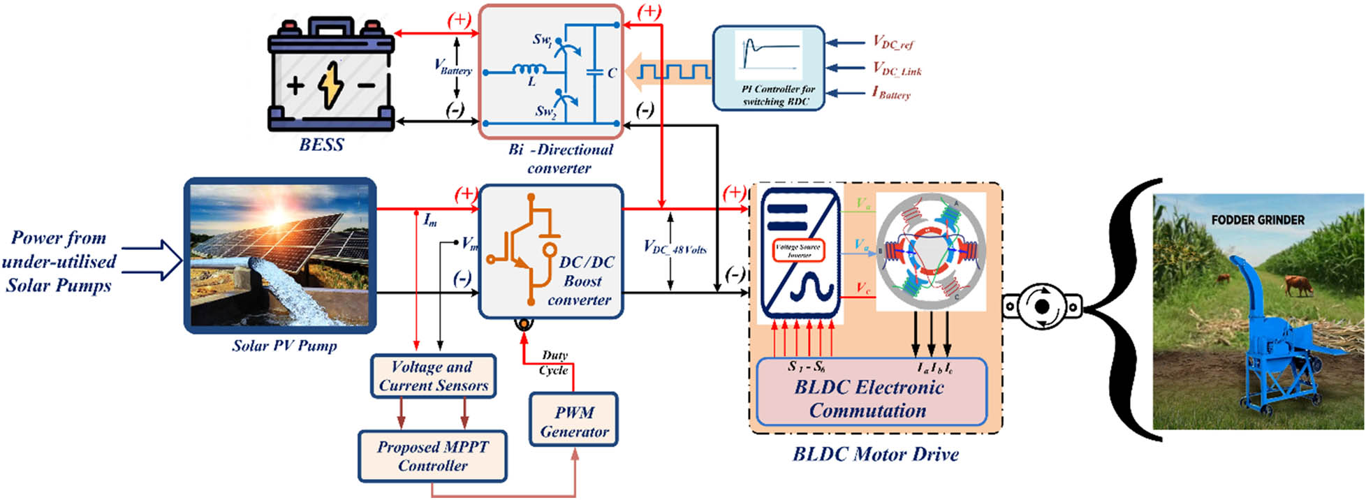
Schematic block representation of developed system representation.
To make the system compatible and inexhaustible, irrespective of solar energy, a battery has to be introduced so that uninterruptable power is supplied for operation. A BDC is involved to make the power flow in both directions for charging and maintaining a constant DC link voltage. As there are various non-linear components present in the DC–DC converter, the power transfer from PV to DC link voltage is slightly less due to losses. This is overcome by suitable maximum power tracking using a Perturb and Observe-based MPPT controller, which has voltage and current sensed from the output of the PV panel as input and provides the duty cycle to extract the maximum power from the PV system. Additionally, input to the BLDC drive is AC fed by a VSI, which converts DC link voltage powered by DC–DC converter to drive the agriculture load coupled to it. The fact is that the proposed system may not be able to perform in variable irradiance or dynamic conditions, and as a result, an ESS has to be introduced to make it fully functional irrespective of the input on the PV system. To confirm the drive is driven at a constant speed, a constant voltage is maintained at the output section of the boost converter during the conversion from DC to AC. The full explanation of the operation is mentioned in Section 4.
3 Designing aspect of proposed system
To develop an effectual and operative PV and BESS-fed BLDC system that is capable of operating under various uncertain conditions, it is necessary to design the model of each component of the proposed topology. The detailed design aspects of all the blocks such as PV system, boost converter, VSI, battery storage system, and BLDC drive to run the agricultural loads are described as follows.
3.1 PV array modelling
A solar PV system consists of PV cells, which is the building block of the system for generating electricity. The individual building blocks are commonly known as the single-diode model, which governs the power generation in a PV system. Figure 2 represents an equivalent single-diode PV cell structure made up of semiconductor material that works on the PV effect for electricity generation. The solar radiations energize the Si-based material for developing the potential difference across the PN junction of the PV cell (Narendra et al. 2020, Kishor and Patel 2022b, Cordeiro et al. 2020).
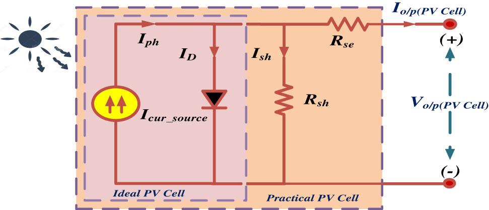
Single-diode equivalent PV circuit.
The output current of the PV equivalent circuit is proffer in the given equation as:
Thus, the total output current of the PV array combining numerous PV cells and modules:
where
where “
The physical changes of the parameters are shown in Figure 3 when the PV array is formed by parallel connections of panels. The characteristics of a constructed solar PV array are shown in the above figures under standard test conditions given in Table 1. The open-circuit voltage, short-circuit current, and maximum power are shown in the portrayed figures.
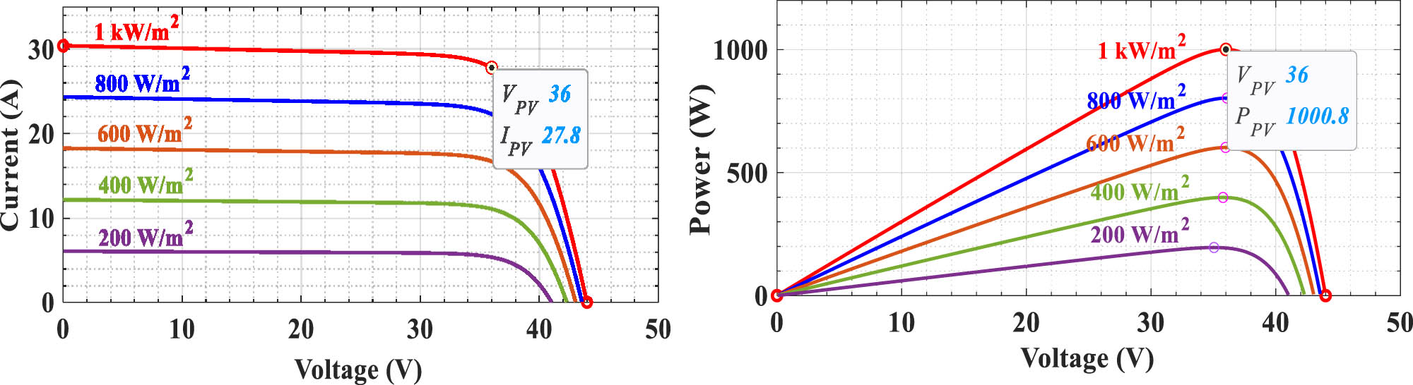
Standard SPV characteristics with variable irradiance.
Experimental description for implemented setup
| Parameters | Values |
|---|---|
| Solar PV module | |
| Peak voltage (V max) | 36 V |
| Open circuit voltage (V OC) | 44 V |
| Current (I max) | 6.95 A |
| Short-circuit current (I SC) | 7.60 A |
| Nominal peak power (P max) | 250 Wp |
| Module efficiency | 15.27% |
| Gross weight | 19 kg |
| Fill factor | 75.31% |
| Maximum operating cell temperature | 47 ± 2%°C |
| Dimensions (L × W × D) mm | 1,640 × 960 × 42 |
| DC–DC boost stage | |
| Input voltage (V in) | 34–38 V |
| Output voltage (V out) | 48 V |
| Switching frequency (f s/w) | 50 kHz |
| Duty cycle (D boost) | 21–29% |
| Inductor rating | 5 mH |
| Capacitor rating | 3,300 μF |
| Battery-based ESS | |
| Battery type | Lead acid |
| Nominal voltage | 24 V |
| Quantity | 2 Nos |
| Ampere rating | 150 A h |
| SoCMin–SoCMax | 40–85% |
| Min. charging rate | 10 h |
| Lifetime of battery | 5 years |
| BLDC motor drive | |
| Output power rating | 1,000 W |
| Armature voltage (V a) | 48 V |
| Armature current (I a) | 25 A |
| Rated speed (N) | 3,000 rpm |
| Torque | 30 Nm |
| Efficiency | 80% |
| Cooling mode | IC411 |
| Insulation grade | F |
| Protection grade | IP33 |
| Agricultural grinder | |
| Body dimensions (W × H × D) mm | (452 × 388 × 385) |
| Table type | Top |
| Grinding drum | SS material |
| Body cast material | Food grade material |
| Stones | 2 |
| Capacity | 3 kg |
| Gross weight | 14 kg |
3.2 Boost converter modelling
The PV system has to work in the maximum power point (MPP) area for proper operation of the BLDC drive, for which a DC–DC power conversion device has to be used. Here, a DC–DC boost converter is placed across the PV array using the P&O algorithm for tracking maximum power (Errouha et al. 2019, Shongwe and Hanif 2015, Batzelis 2019, Kishor et al. 2021). The requirements for a basic boost converter are inductor (L), capacitor (C), and duty cycle (D) for operating the semiconductor switch (Q) to maintain MPP and DC-link voltage. The DC–DC boost schematic diagram in Figure 4a and b shows the voltage across the diode during different phases of the boost converter's switching cycle.
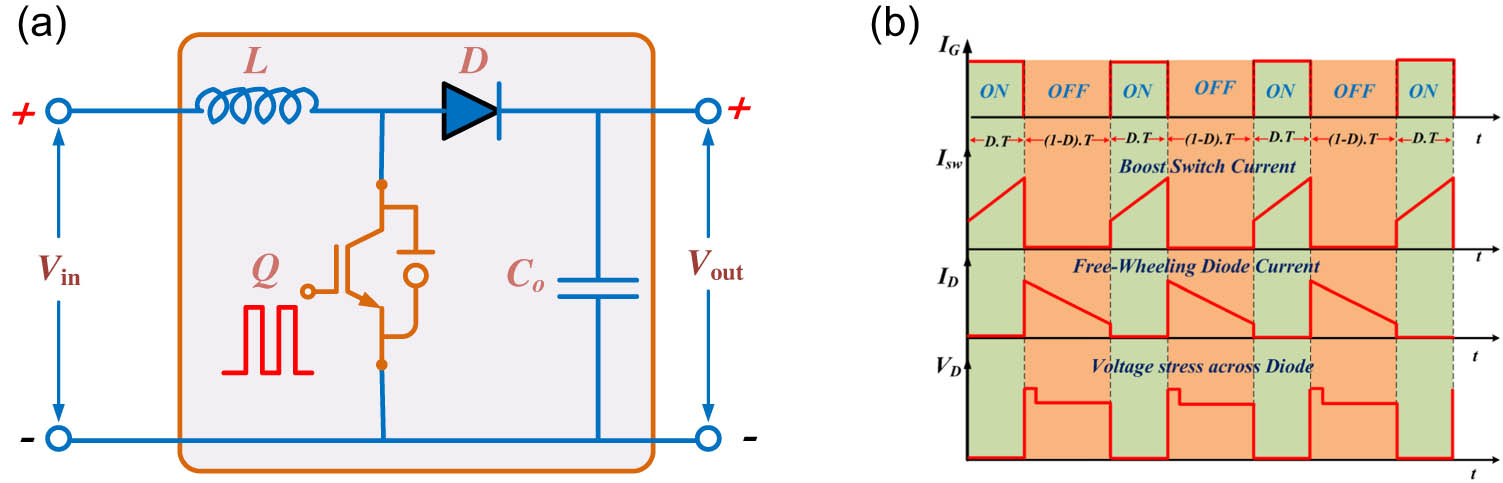
(a) Schematic of DC–DC boost converter, (b) voltage stress across the switch and diode.
When the value of the inductor has the proper inductance, it is capable of handlining the peak and RMS values of currents over a wide range of input and output voltages (V in & V out), specifically taking the frequency of the circuit into consideration. The maximum permissible ripple current (ΔIL) is 30% of the maximum value of load current (IL) used in the converter at the least duty cycle. If f s/w is the converter's switching frequency, to determine the value of the ideal inductor value should be:
where
The capacitors placed at the output terminal are seen as filters in a boost regulator to overcome output voltage ripples and high RMS current stress. The maximum allowable voltage ripples (ΔV L) are dependent on the minimum value of output capacitance at a steady state in the boost converter. At given limits of output ripples (ΔV L), the expression for calculating the minimum value of capacitance required for the converter is given as follows (Table 2):
Specification of semiconductor devices used
| Semiconductor device | Parameter | Symbol | Value | Unit |
|---|---|---|---|---|
| MOSFET | Drain–source voltage | VDSS | 60 | Volts |
| Drain current (continuous) | I D |
|
Amps | |
| Gate–source voltage | VGSS |
|
Volts | |
| Gate resistance | R G | 5 | Ohm | |
| Permissible junction operating temperature | T J | −55 to 150 | °C | |
| Diode | Forward voltage | V f | 1,000 | Milli-volts |
| Reverse voltage | V r | 75 | Volts | |
| Reverse recovery time | T rr | 8 | Nanosecond | |
| Maximum forward current | I f | 300 | Milli-amps | |
| Maximum reverse leakage current | I r | 5 | Micro-amps |
The semiconductor component is the main switching element of a DC–DC power conversion device, which can withstand the maximum possible voltage and current dynamics. In this converter, a low-resistance N-channel MOSFET with a switching characteristic of [T on = 14 ns, T off = 50 ns] is used for operation. The electrical characteristics are listed in Table 3.
Bidirectional converter operational modes
| DC link voltage | BDC mode | Battery mode | Switch action |
|---|---|---|---|
| V DC_Link < 48 volts | Buck converter | Charging | Sw_1 = ON |
| Sw_2 = OFF | |||
| V DC_Link > 48 volts | Boost converter | Discharging | Sw_1 = OFF |
| Sw_2 = ON |
3.3 ESS modelling
The ampere rating of any battery calculation depends on continuous working hours, efficiency, maximum allowable depth of discharge (DoD), and state of charge (SoC). The state of charge is a percentage that tells you the level of battery charge relative to its full capacity and is expressed in an integer range from 0 to 100%. Depth of discharge is the inverse of state of charge, so a DoD value of 100% means the battery is empty, while 0% indicates that it is fully charged. SoC is usually used when talking about the current battery state, while DoD is more often used when talking about the battery’s history and how it degrades over repeated use. The following formula shows the relationship between SoC and DoD.
The battery bank is sized to have enough power to last for days where there is less sun, called the days of autonomy. The depth of discharge for deep-cycle batteries is typically 80%, but if you are using this design, it is taken to be 65%. The temperature correction factor is different at high or low temperatures. As an example, at low temperatures, battery efficiency decreases, so the temperature correction factor would be 0.9. Battery life is supposed to be 10 years, according to the manufacturer’s specifications. The required battery capacity in A h depends on the load given by:
Here,
Batteries connected in parallel:
Batteries connected in series:
where
Therefore, total series and parallel batteries connected in the battery bank:
3.4 Bidirectional converter modelling
The BDC enables to control the power flow from PV to battery and vice versa by adjusting the voltage VPV of the PV output at the MPP during normal operation. By using the above function, BDC can adjust the battery’s charging and discharging modes, which are dependent on the difference between the load and PV power (Wu 2022). The following figure shows the schematic design of a BDC, which has the ability to change the level of voltage between the input and output. It operates in two different modes: buck mode and boost mode. Buck mode operates whenever the Ppv power is sufficient to drive the load itself; this takes place when the switch Sw_1 is ON and the battery starts charging. When the power from PV is not able to drive the load demand, the boost mode gets in position by operating the switch Sw_2. This makes the DC link voltage be maintained at the constant mentioned voltage (Jadhav et al. 2018, Iqbal and Islam 2017). The swapping of power takes place by providing reasonable switching signals to operate switches present in the BDC for transient conditions (Figure 5).
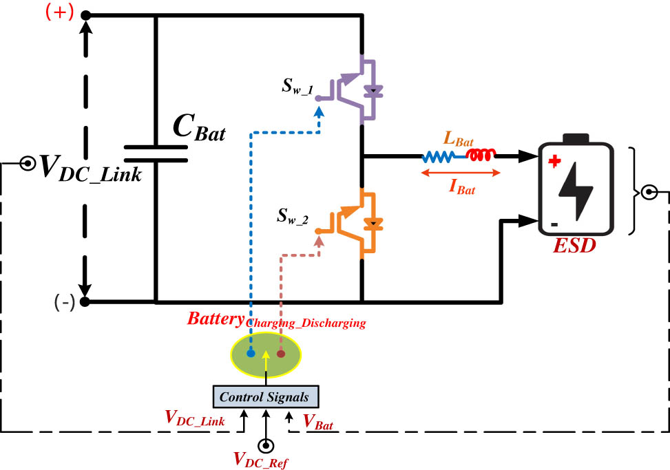
BDC/battery structural design for uninterrupted power supply.
For smooth operation of BDC, the control circuit of the BDC works in two operating regions, as shown in Table 3. In addition to the above factors L and C selection also plays a vital role while in operation. The modelling of the inductor and capacitance values for a proper BDC is as follows:
3.5 BLDC-motor with electronic commutation modelling
For solar PV applications, BLDC motors are widely accepted over other conventional motors, i.e. induction, DC, and special motors. BLDC motors are taking over the traditional AC induction and DC motors due to their higher efficiency, minimal maintenance, reliability, and extended lifetime. They have a longer lifespan than traditional motors, as they do not have brushes that can wear out over time. This means they require less maintenance and have a longer operating life. BLDC motor drives can provide precise speed control over a wide range of speeds, making them ideal for applications that require precise control over motor speed. BLDC does not depend on the mechanical system (brushes) to control the current to the rotor for developing torque to drive the load (Darcy Gnana Jegha et al. 2020, Shanmugam et al. 2019, Jena 2019). Due to the absence of brushes, the BLDC is compact in size and weight with the same ratings as traditional motors. It makes to provide a high torque-to-weight ratio which almost reduces the energy consumption by 40% on average conventional motors, defining itself as an energy-efficient prime. With solar PV being an unreliable provider of consistent power, batteries have been ruled out as a potential alternative. To ensure reliable delivery of electricity, ESD is now being used as the other source of supply for driving the BLDC drive (Kumar et al. 2022, Kumar 2019) (Figure 6).
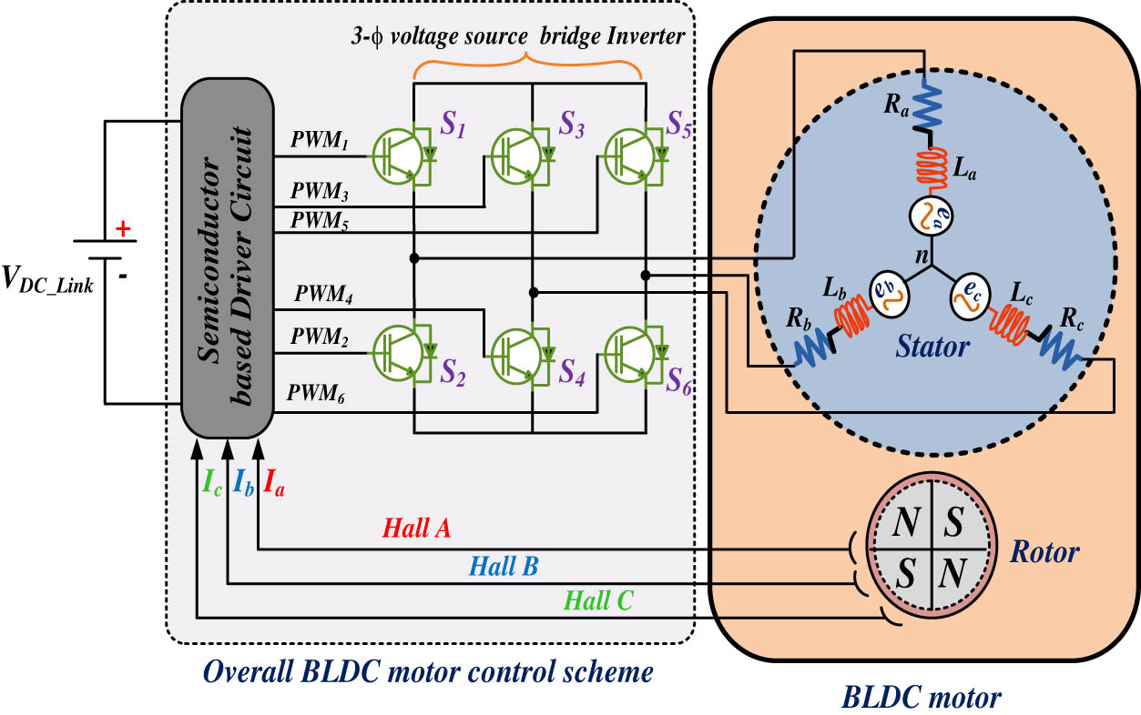
Schematic view of BLDC motor control.
Operating a BLDC motor uses a VSI for power to commutate the rotor by providing a switching logical pulse from the absolute positioning. The BLDC drive is also branded as an electronic commutated motor. The VS inverter basically works on the semi-conductor driver circuit, which provides six signals as shown in Table 4.
Switching sequences based on hall effect signal states
| θ (°) | Hall signals | Back emf’s | Switching states | |||||||||
|---|---|---|---|---|---|---|---|---|---|---|---|---|
| H a | H b | H c | e a | e b | e c | S 1 | S 2 | S 3 | S 4 | S 5 | S 6 | |
| NA | 0 | 0 | 0 | 0 | 0 | 0 | 0 | 0 | 0 | 0 | 0 | 0 |
| 0–60 | 1 | 0 | 1 | 0 | −1 | +1 | 1 | 0 | 0 | 1 | 0 | 0 |
| 60–120 | 1 | 0 | 0 | −1 | +1 | 0 | 1 | 0 | 0 | 0 | 0 | 1 |
| 120–180 | 1 | 1 | 0 | −1 | 0 | +1 | 0 | 0 | 1 | 0 | 0 | 1 |
| 180–240 | 0 | 1 | 0 | +1 | 0 | -1 | 0 | 1 | 1 | 0 | 0 | 0 |
| 240–300 | 0 | 1 | 1 | +1 | -1 | 0 | 0 | 1 | 0 | 0 | 1 | 0 |
| 300–360 | 0 | 0 | 1 | 0 | +1 | -1 | 0 | 0 | 0 | 1 | 1 | 0 |
| NA | 1 | 1 | 1 | 0 | 0 | 0 | 0 | 0 | 0 | 0 | 0 | 0 |
From the above figure, three stator windings and permanent magnets on the rotor make up the BLDC motor. Due to the high resistivity of both the stainless-steel retaining sleeves and the magnet, rotor-induced currents can be disregarded, and no damper windings need to be modelled.
The voltage equations of three windings can be written as follows:
where
Let
The back emf’s
Due to their trapezoidal shape, the induced back emf’s lack sharp corners. The flux linkage derivatives produce the electromagnetic fields, which are a continuous function. The flux density function is smooth with no sharp edges, thanks to fringes. Thus, electromagnetic toque in BLDC is defined as:
Table 1 illustrates the motor specifications employed for this proposed system to operate the BLDC drive agriculture unit. The SPV array output power is optimized by the P&O MPPT technique. The design and control of the proposed system are elaborated as follows.
4 Control schematic
In the proposed system, the maximum power of the SPV array is tracked using the P&O MPPT technique, and the DC link voltage is maintained by the DC–DC boost converter in combination with the BDC-ESS for feeding the BLDC drive to operate through the electronic commutation. These two controls at various stages are discussed in brief in the following sub-sections.
4.1 Proposed MPPT control for PV system
For harvesting maximum energy from the sun, the PV system here makes use of the P&O MPPT algorithm for tracking maximum output. For achieving MPPT, a DC–DC boost conversion system is interfaced in the mid-section of power flow from the source (i.e. PV system) to load. The algorithm adjusts the duty ratio (
The step size must also be large enough to prevent noise from interfering with and to enable the perturbation to result in a discernible change in array output power. The performance of the MPPT method is significantly impacted by noise, particularly at low step sizes where the system's response to noise is comparable to the MPPT perturbations. The perturbation is held in the same direction if ΔP is positive, which indicates that the algorithm is getting close to the maximum panel power. If the output power diminishes, however, the perturbation must be applied in the other direction.
Figure 7 shows that the MPP is attained by the expression ΔP = 0 in below displayed P&O algorithm’s flowchart.
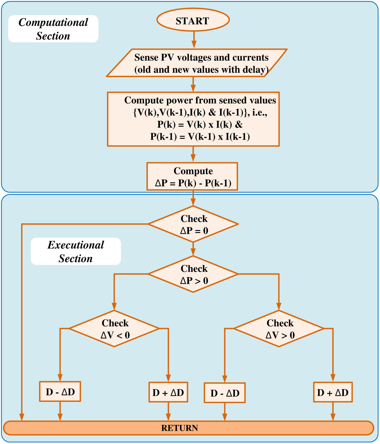
Conventional P&O algorithm flowchart.
Evidently, the perturbation step size affects whether the MPP is reached since a large step size may result in a fast-tracking response but also high steady-state oscillation amplitudes. On the other hand, if the step size is small, tracking will be slower, and there will still be a small oscillation. The fundamental drawback of the P&O method is continuous oscillation around the MPP. Unfortunately, it is a cause for energy losses and an undesirable phenomenon termed MPPT drift, as described in Figure 8, where two power–voltage curves are presented at varying irradiation levels. The typical operation sequence is 1-2-3-2-1 indefinitely under steady-state circumstances with constant irradiation. Let us assume, however, that the irradiance increases sharply when the operational point shifts from 2 to 3. The operational point thus shifts to 4. When the algorithm detects a rise in PV power, the next perturbation is applied in the same direction, resulting in the culminating operation point being 5, which results in instability and power losses. The next section introduces the modifications to the standard P&O algorithm that aim to counteract the MPPT drift phenomena and fast convergence. By introducing an additional measurement in the course of the MPPT period, the proposed technique improves the assessment of the power fluctuation in contrast to the standard P&O.
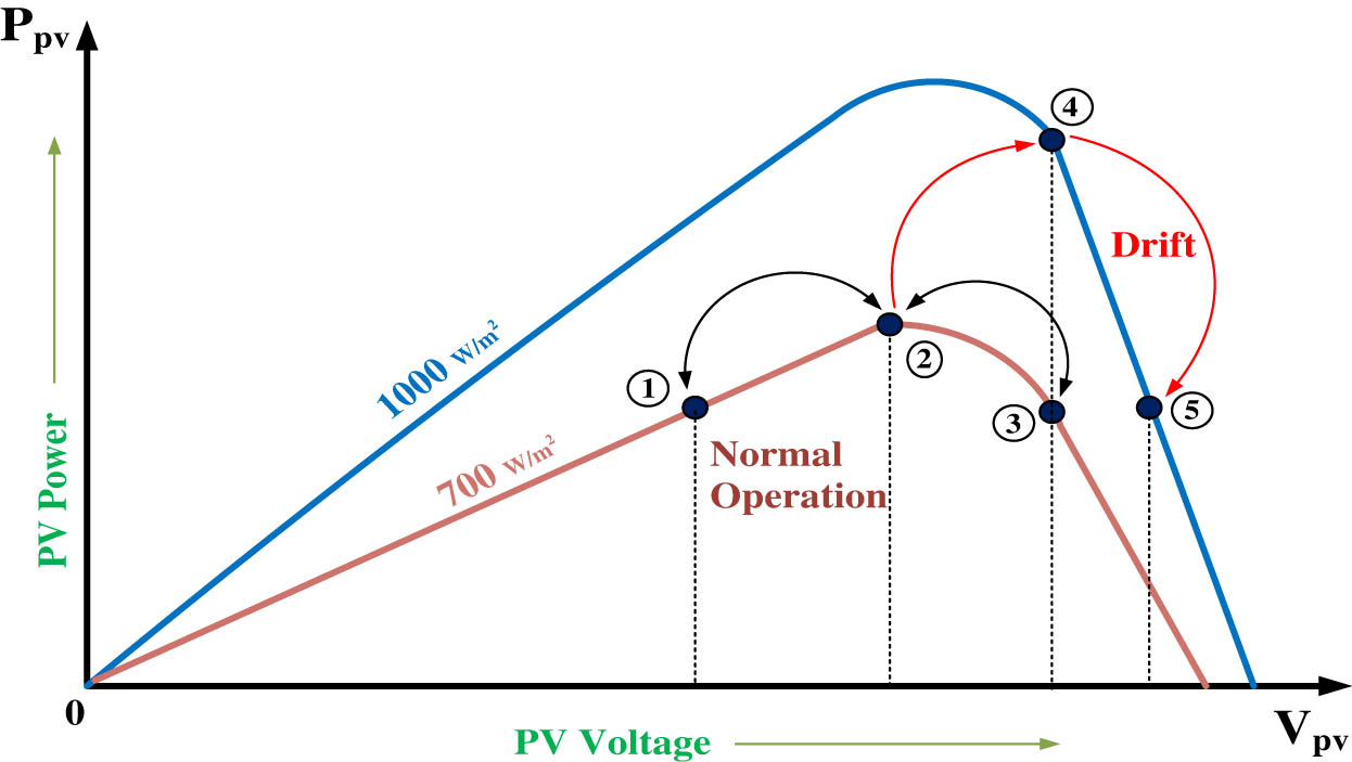
Drift occurrence while irradiance variation in P&O algorithm.
Therefore, in this approach, the power variation brought on by the perturbation imposed and the one carried on by the change in irradiance may be isolated to some extent. The addition calculation is accomplished in the execution part of Figure 9 by inserting a decision step that investigates whether the criterion ΔP and ΔV, which resemble the MPP area for that irradiance value, is zero or not. Now, two positions [(Vx, Px), (Vx − 1, Px − 1)], which are spaced apart by a signal step change (ΔD), establish the area of convergence. Therefore, the new ΔD New is 90% less than the previous one for searching in this area. The new duty cycle ΔD New is described as follows:
and
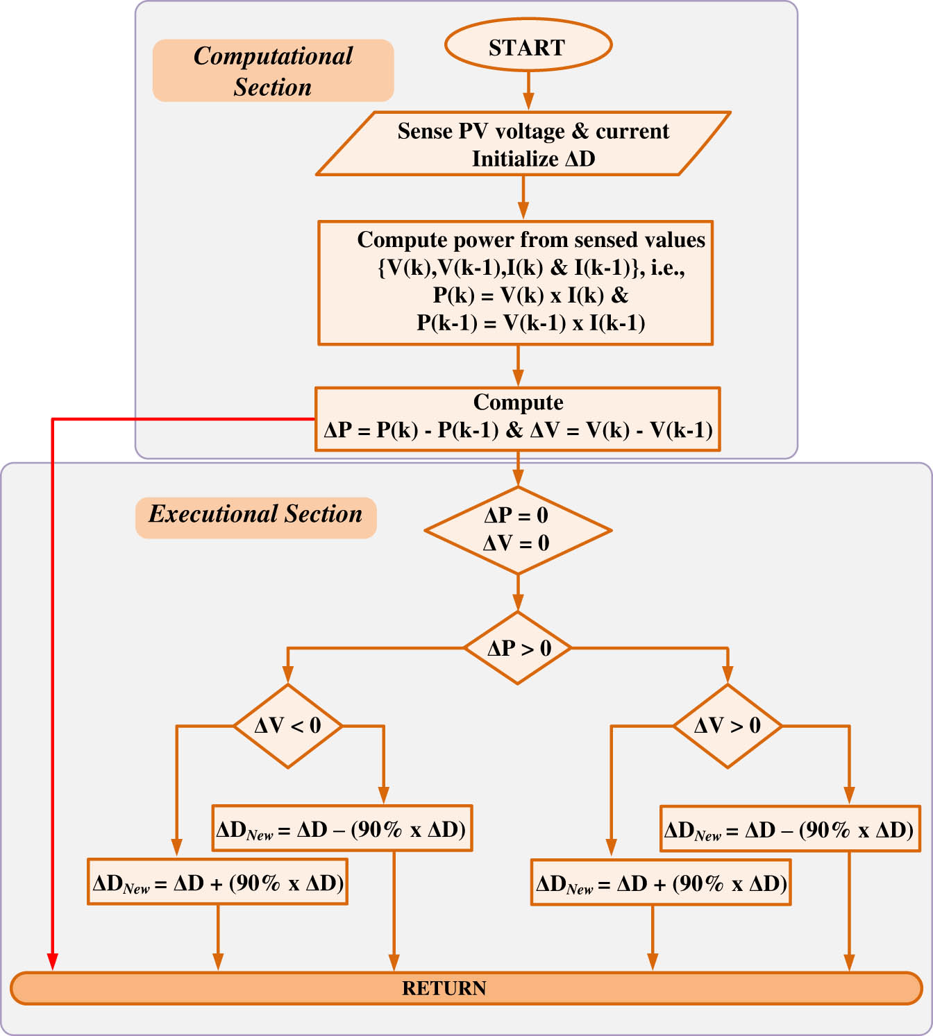
The implemented P&O algorithm MPPT.
The algorithm's step size plays an important role in making it adaptable for approaching the MPP. The duty cycle is multiplied by a correction factor shown in equation (18) that is directly proportional to the PV module's voltage and inversely proportional to its current when the algorithm is approaching the MPP to the right. In a similar manner, when the algorithm is approaching the MPP to the left, the coefficient is directly proportional to the current and inversely proportional to the voltage. The methodology helps to monitor the MPP more accurately since the step size drops as it approaches the MPP, as depicted in the above flowchart in Figure 9.
4.1.1 BDC and ESS control
For uninterruptable power supply to the BLDC drive for continuous operation, a battery bank unit with suitable power flow management is described in the below section. This is performed by means of systematic control of the charging and discharging of batteries used during operation. The operational control for the battery is shown in Figure 10, which states the power flow, i.e. charging and discharging procedures during the operational events. The energy storage device is designed in such a manner that if the battery SoC is greater than the reference SoC, it gets discharged and charged whenever the SoC gets less than the reference SoC till the maximum SoC. Therefore, battery charging can be adjusted according to the energy management requirements and strategy. The SoC of the battery is made to operate at 40%, which can be modified depending on the mentioned data sheet of the used battery.
Schematic diagram of BDC control strategy for maintaining constant DC link.
The battery is treated as a simple DC voltage source with series negligible internal resistance (R int.). The selected battery model is a R int. Equivalent, which is widely used for dynamic studies due to its reasonable performance with simple configuration and low count of parameters. The battery state of charge and DC voltage are inversely proportional and can be calculated according to Coulomb’s method:
where
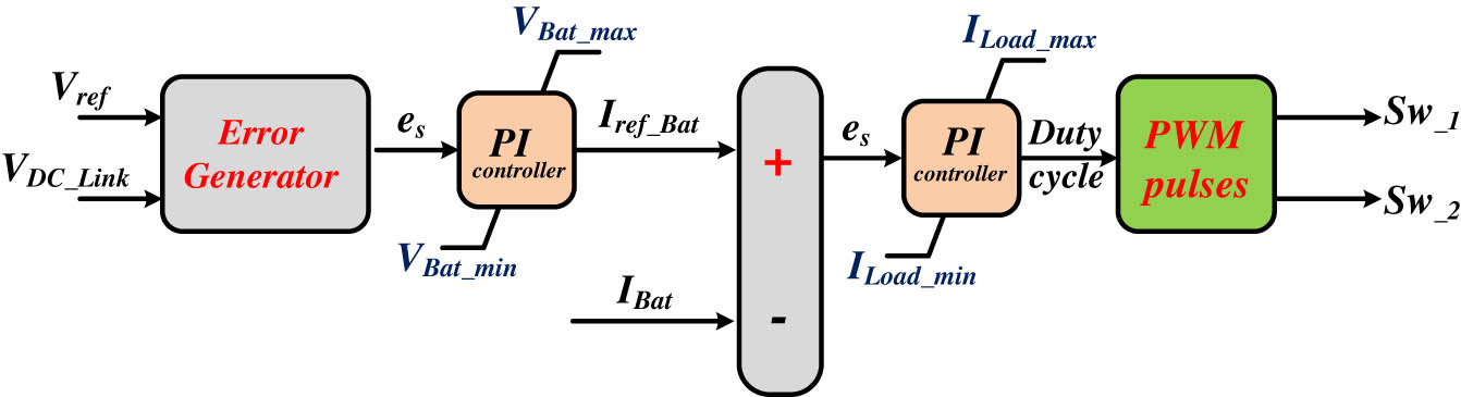
To achieve the above control for maintaining a constant DC voltage across the DC link, a PI-control BDC converter is employed in parallel with the PV source. The PI operates the two switches present in BDC by continuously observing the reference voltage of the DC link voltage across the DC link (
From Figure 10, switching a PI (Proportional-Integral) controller in a bidirectional converter system can ensure that the converter can provide power in the event that the PV system fails. The PI controller is used to control the power flow between the PV system and the battery through BDC switches, as shown above. When the PV system fails to provide power, the PI controller can be configured to switch the bidirectional converter into power supply mode, allowing it to provide power to the load which is accomplished by V ref , V DC_link voltages and battery current (I Bat.).
The process of switching the PI controller involves changing the controller's setpoint. In normal operation, the setpoint is set to zero, which means that the bidirectional converter operates as a power flow controller, directing power from the PV system to the ESS when it is producing excess power and from the ESS to the load when the PV system is not producing enough power. When the PV system fails, the setpoint can be set to a positive value, which signals the bidirectional converter to operate as a power supply, providing power to the load. In addition to switching the PI controller, other measures may also be necessary to ensure smooth and reliable operation of the bidirectional converter in power supply mode. These measures may include adjusting the voltage and current limits of the converter, implementing voltage regulation, and monitoring the health of the batteries. In the end, switching the PI controller in a bidirectional converter system can provide a backup power supply in the event that the PV system fails. This can ensure continuity of power to the load and help maintain the stability of the operation of the BLDC drive for processing the mechanical loads.
4.2 Implemented control for optimal operation
The below flowchart describes the power management between a solar PV system and an energy storage device aided by BDC to drive BLDC-driven agricultural mechanical units. The PV power and load power are measured and compared so that the PV itself can drive the load or not. If PV power is greater than the load requirement, the power is transferred to both the BLDC drive and the battery for charging until it reaches rated capacity. When the PV fails to drive the load, then power transfer takes place from the energy storage device for its operation (Figure 11).
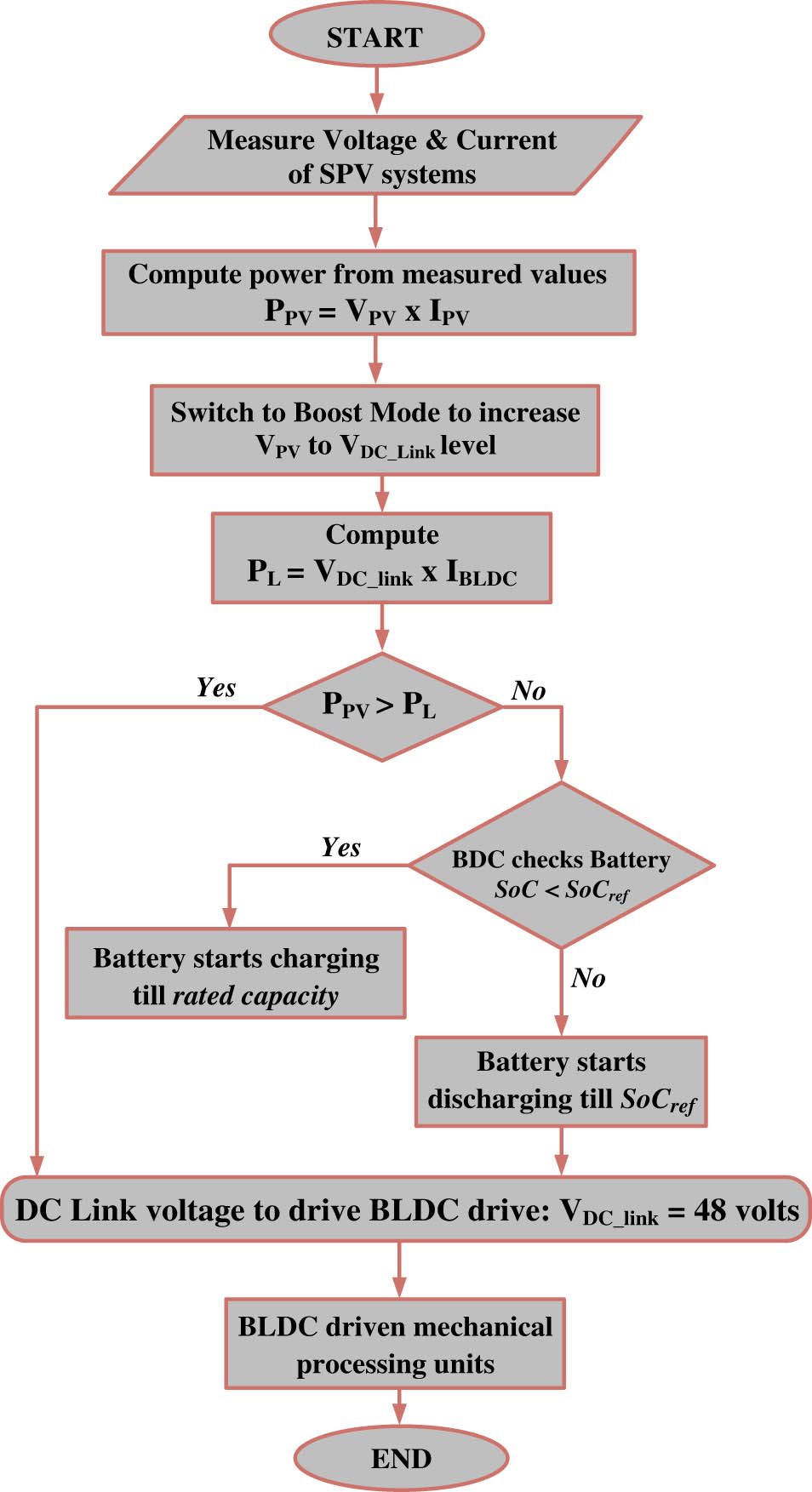
Flowchart describing the power management between solar PV and ESD to drive BLDC motor.
5 Experimental analysis and discussions
The implemented architecture is validated by utilizing the dSPACE 1103 controller, a 1 kW BLDC motor, and an electronic commutation power module. The solar part of the hardware prototype is achieved by the solar array simulator for PV voltage and PV current. The experimental setup of the developed prototype is shown in Figure 12. The current and voltage sensors provide analog signals which are converted into digital signals using the ADC available with dSPACE1103. To carry out the electronic commutation, the hall signals will be directly transmitted via digital I/O pins. The performance of the system can be determined based on dynamic conditions. The solar PV voltage, PV current and Power of PV with its duty ratio, DC–DC converter voltage, the current through energy storage elements, the stator phase currents, and speed parameters for VSI conversion efficiency are considered as PV array performance parameters. The performance of the developed hardware prototype is demonstrated under various operating conditions. The performance of the proposed battery-integrated PV system to drive the BLDC drive is figured out under different insolation levels and recognized in terms of solar PV array voltage (V pv), array current (I pv), PV array power (P pv), DC–DC boost conversion voltage (V Boost), battery voltage (V Bat.), battery current (I Bat.), state-of-charge of battery (SoC%), BLDC motor electromagnetic torque (T BLDC) & motor speed (N rpm), motor back emf’s voltages (e a , e b , and e c ) and stator three phase currents (I a , I b , and I c ), and DC link voltage (V DC_Link) for steady operation. The proposed system was stimulated for three conditions of solar irradiances: (i) under standard test conditions (with G = 1,000 W/m2 and T = 25°C), (ii) gradual decrease and increase in solar irradiances, (iii) dynamic decrease in radiations level in sun’s energy and sudden blackout of solar’s insolation level and the waveforms were plotted for these criteria.
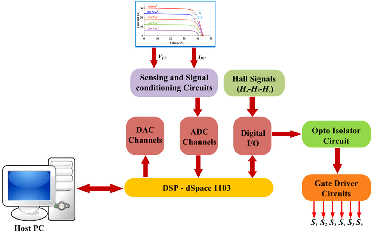
Block representation of developed hardware prototype.
5.1 PV performance for different insolation levels
The performance of a PV system can be evaluated by studying its response to changes in the amount of sunlight it receives, or solar irradiance. By comparing the hardware results seen in Figure 13 to the expected performance under STC conditions, it is possible to determine the efficiency and performance of the system. The results indicate that the system is operating more efficiently than expected or that the cells are producing more power to their rated capacity for the time period, t0 – t1 s. Under slow irradiance change, the solar irradiance is gradually increased or decreased over a period of time, as shown in Figure 12 from t1 to t2 time period. This test is used to observe the response of the system's maximum power point tracker (MPPT) and to determine the voltage-current characteristics of the PV cells. The results of this test evaluate the system's efficiency and its ability to track the MPP under gradually varying conditions. In contrast, a step irradiance change involves rapidly changing the solar irradiance from one level to another, such as going from full sun to shade or vice versa. This test is used to evaluate the system's ability to quickly respond to changes in solar conditions and to track the MPP under rapidly changing conditions from t2 to t3 time period. The results of this test can be used to evaluate the system's dynamic performance and to identify any potential issues with the MPPT algorithm or system components.
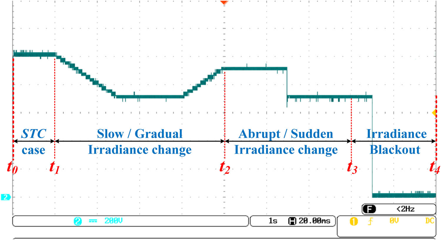
Experimentally investigated out power waveforms of SPV system for varying solar irradiances.
Both slow irradiances change and step irradiance change tests are important for understanding the performance of a PV system and for optimizing its design and operation. When referring to PV performance under a rapid loss of sunlight or zero insolation. This can occur, for example, during a cloud passing over the PV panels or during a sudden power outage. The PV system is equipped with a DC–DC converter, and as a consequence, it will immediately shut down to generate power to prevent back-feeding from the system. When a system includes energy storage, the stored energy can be used to continue providing power to the system. In conclusion, the performance of a PV system under sudden zero insolation levels can be characterized during the time period from t3 to t4, which rapidly decreases the power generation and gets shut down as per the components and design of the system.
5.2 DC–DC boost and BDC performance under different conditions
A DC boost converter with a battery-operated bidirectional converter is used in the proposed architecture for the SPV system. The experimental results given in Figure 14 show a DC–DC boost converter with a battery-operated bidirectional converter that affords to convert the PV voltage to the required DC link voltage level to drive the BLDC drive for processing the mechanical units. The waveform depicts information about the performance and efficiency of the device, as there are no voltage spikes, overshoots, and undershoots to achieve the targeted voltage for the DC link voltage.
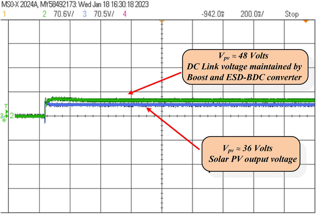
Experimentally investigated output voltage waveforms for SPV and DC–DC boost converter.
As shown from the above result in Figure 15, it is impossible to identify any issues with the BDC converter. The waveform illustrates the optimized performance of the converter by adjusting the duty cycle of the pulse width modulation (PWM) signal and the control parameters of the converter. The battery management for charge and discharge events is well controlled by the PI controller battery life and prevents damage to the battery while switching periods. These results show the optimized converter's operation, improve battery management, and ensure the reliable and efficient operation of SPV systems (Figure 16).
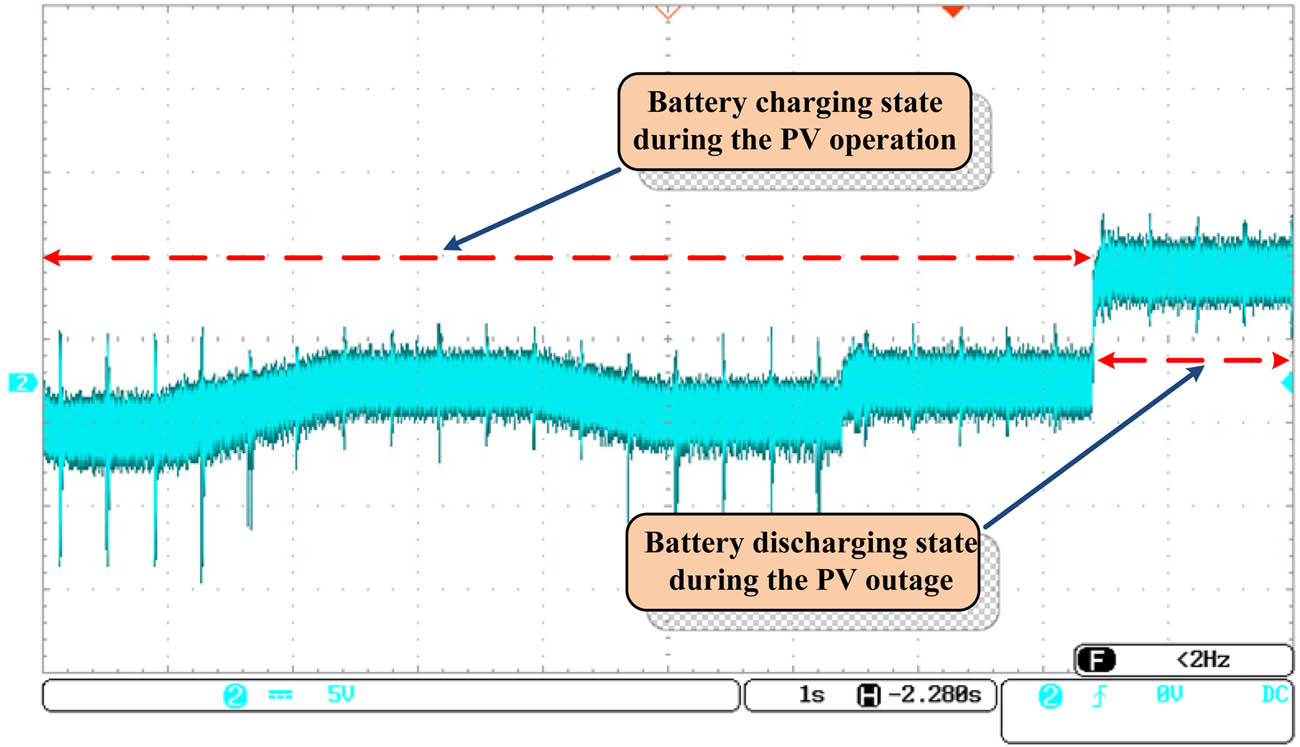
Experimentally investigated waveforms for ESD for maintaining a constant DC Link voltage.
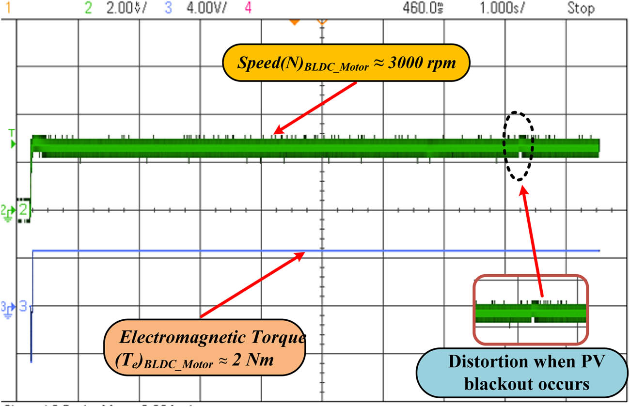
Experimentally investigated waveforms for speed vs torque of BLDC motor.
5.3 BLDC-driven mechanical load units
Figure 17 shows a three-phase BLDC drive with a six-step commutation pattern. Operating under a constant load of 2 Nm and a speed of 3,000 rpm, the amplitude and frequency of the waveforms are maintained constant throughout the operation. However, the power outage does not create a big difference in speed and torque, which can be observed in a magnified view from the above figure. Overall, the waveforms for a BLDC drive operating under a constant load of 2 Nm and a speed of 3,000 rpm with variable input power are complex and define that the control strategy used by the drive is up to the mark. The BLDC drive controller is able to generate the commutation to maintain the desired speed and torque.
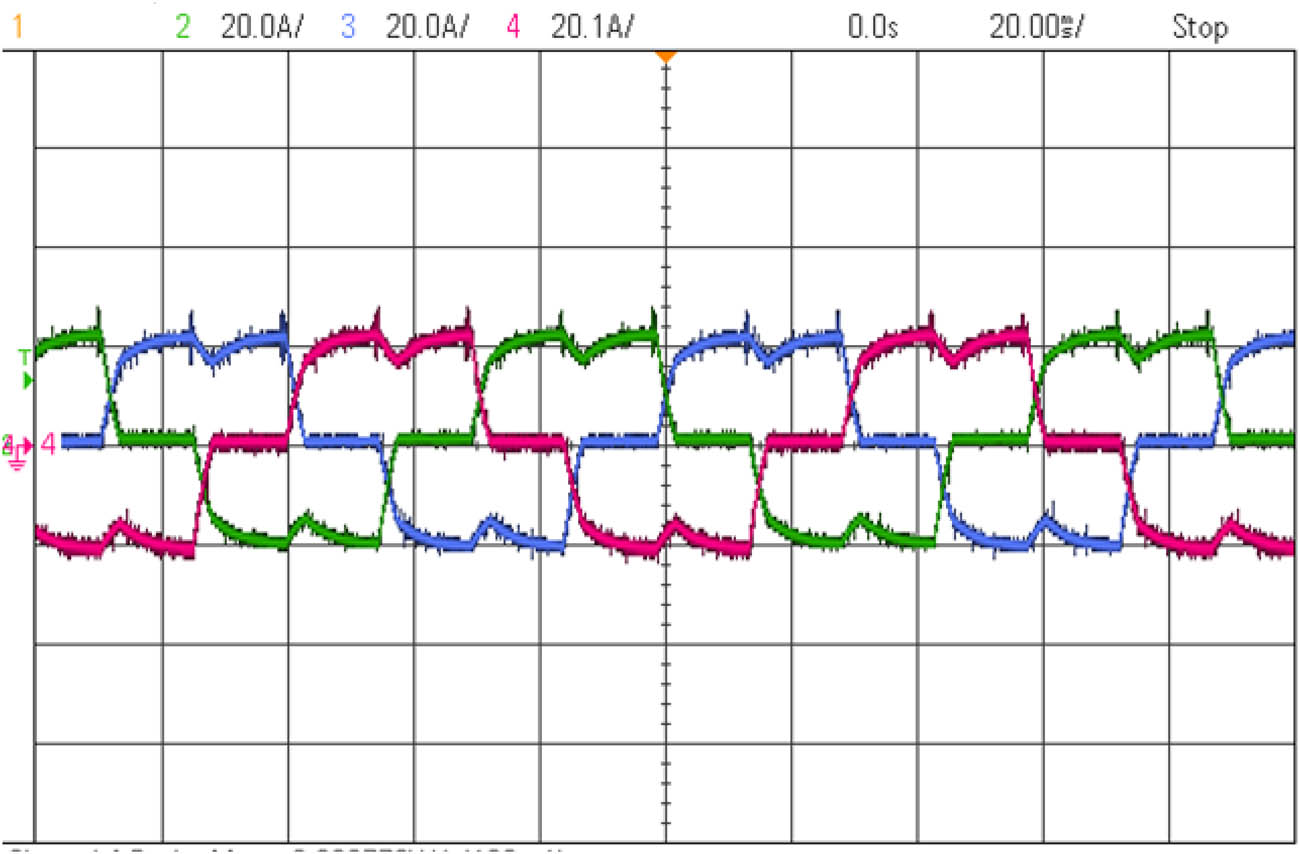
Experimentally investigated waveforms for BLDC motor 3-ϕ stator currents.
In order to produce a rotating magnetic field in the air gap, the stator current should be periodic in nature for creating a torque as output at the rotor shaft. Thus, the three phases of stator winding are energized by VSI, which produces a rotating magnetic field to drag the rotor towards itself. The above waveform in Figure 17 shows that they are periodic with the proper level of stator current as specified per motor design, the load, and the desired speed and torque. The motor's behaviour under different operating conditions requires a proper control of the stator current through the PWM technique to enhance the motor's performance and efficiency.
Figure 18 validates the performance of a Brushless DC (BLDC) motor whose back EMF waveform of a BLDC motor has a characteristic zero-crossing pattern that can be seen above as the motor accelerates to 3,000 rpm. The zero-crossing waveform of the BLDC motor's back EMF is a critical parameter that implies control and operation of the motor, permitting precise commutation and optimal performance. The pulses are used to determine the position of the rotor and to switch the motor's phases at the proper period for optimal performance and efficiency, which is observed in subpart (b) of the above figure.
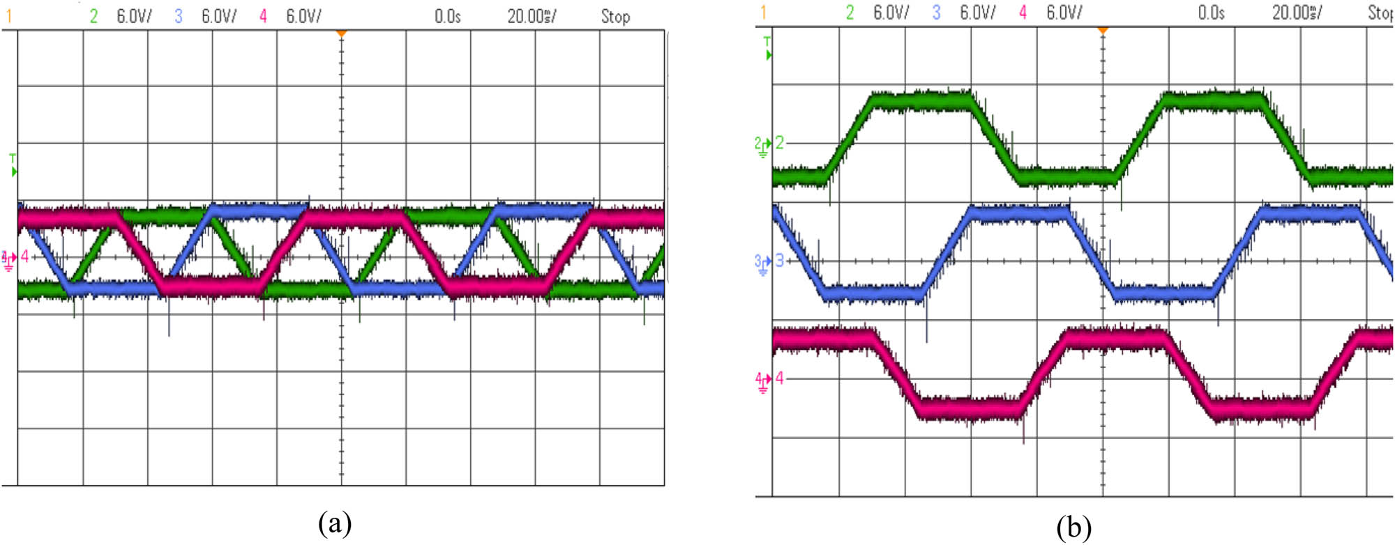
Experimentally investigated waveforms: (a) BLDC motor 3-ϕ back EMF’s and (b) view of 3-ϕ back EMFs separately showing zero-crossing detection.
6 Comparative assessment of proposed system
The comparison of the total number of components in the different existing topologies is shown in Table 5. It is conceivable that the presented topology has a lower number of components, which results in a reduction in the switching losses faced by the system and enhances its performance. The proposed system has fewer components compared to similar topologies as listed in Table 5, whereas it can be noticed that the topology (Zhu et al. 2014) is similar in the case of semiconductor switches but there components varies in the case of capacitor and diode count.
Comparison of components of proposed topology and other existing topologies
| Components | Udayakumar et al. 2023 | Zhu et al. 2014 | P. S. |
|---|---|---|---|
| No. of input ports | 2 | 2 | 2 |
| No. of output ports | 2 | 2 | 2 |
| MOSFETs | 3 | 3 | 3 |
| Inductors | 2 | 2 | 2 |
| Capacitors | 1 | 5 | 2 |
| Diodes | 2 | 3 | 1 |
| Total no. of devices | 12 | 17 | 12 |
| Input voltage (volts) | 36 | 100 | 36 |
| Output voltage (volts) | 110 | 50 | 48 |
| DC–DC Conversion efficiency η (%) | 80 | 90 | 95.8 |
| PV Power rating (Watts) | 1,800 | 1,500 | 1,000 |
P.S. – proposed setup.
Despite the variation in switch count, the efficiency of the DC–DC converter is higher in proposed topology since the input and output voltage variations are not very large. Thus, it makes the power conversion process simple when comes to switching the duty cycle for the converter.
7 Economic feasibility analysis
Due to the existence of IMDs, power quality is low in small-scale industries, households, and commercial establishments. Apart from IMDs, they cause voltage distortion in utilities and unbalancing operations impact negatively the distribution system's power quality. Solar PV technology has been employed in a broader context as an ecologically good substitute for diesel- and electricity (based on fossil fuels)-powered water pumps. SPVWPS has been installed where grid connectivity is not accessible, and access to fossil fuels is not possible due to inadequate transportation infrastructure. Furthermore, the use of SPVWPS is a more suitable choice because of the natural bond between the accessibility of solar power and the requirement of water. Interdisciplinary technical expertise is required for its maintenance and operation. Economic feasibility analysis is required to provide a net benefit in the long term even though the system is technically well developed.
The stated agricultural load is run by the electric grid, and the electricity tariff is assumed to be 0.067 $ or 5–6 ₹. Even though the government offers free electricity to the agricultural sector, we assumed this tariff to show the expenses incurred by the government for the operation of the grid utility. This system uses 14 kW h per day and has a peak power output of 1 kW. Using the power grid alone, the current system operating costs for electricity are $342.37 or ₹28300.30 per year. The proposed strategy can reduce the cost of running over a project life of 25 years, which can be observed from Table 6.
Cost analysis for solar PV- and diesel-operated agricultural mechanical loads
| Sl. No. | Parameters | Diesel generators (₹) | Solar PV system (₹) |
|---|---|---|---|
| 1. | Capital cost | 30,000/- (2 kVA) | 45,000/- (2 kW) |
| 2. | Installation cost | 1,000/- @ (2% of capital cost) | 20,000/- (2% of capital cost) |
| 3. | Fuel cost | 1,10,000/- @ (200 days × 5 L/day) | Nil |
| 4. | Replacement cost | 30,000/- | Nil |
| 5. | Maintenance cost | 1,500/- @ (5% of capital cost per year) | 500/- @ (1% of capital cost per year) |
| 6. | Motor and electronic drive | Nil (pulley driven) | 15,000/- |
| 7. | Life cycle period | 6–7 years only | 20–25 years |
| 8. | Payback period | 3 years | 4 years |
8 Conclusion
This article presents an effective energy conversion system that utilizes the power of underutilized pre-installed solar pumps to drive a BLDC motor-coupled agrarian load. The proposed off-grid pre-installed SPV system is capable of effectively managing untapped solar PV power to increase utility and agricultural output, hence increasing farmer revenue. Additionally, the presented system is a better alternative for the green energy transition in agricultural activities while limiting the carbon footprints associated with conventional methods of driving these agrarian loads. The focus of the study is on the design and implementation of efficient systems for farming communities. The initial system validation is performed in MATLAB/Simulink and is then proven experimentally, demonstrating the overall effectiveness of the proposed system. Experiments are carried out in various operating situations to demonstrate the efficacy of the proposed system. During weather intermittency, the system is capable of maintaining the desired voltage level at the load bus. The system is also compared to other similar arrangements used to drive agrarian load. As a result, this system provides a long-term and low-cost alternative for powering BLDC drivers in agricultural applications. Furthermore, the proposed system can be expanded to power various agrarian loads such as an oil mill, chaff cutter, farm buildings, pesticide sprayers, and so on. The economic analysis additionally revealed that diesel pumps often exhibit a lower initial investment cost but incur much higher expenses for operation and maintenance. compared to Solar pumping, in contrast, has a significantly larger initial investment but boasts fewer recurring expenses associated with operation and maintenance.
-
Funding information: No funding.
-
Author contributions: Varjana Hemant Kumar: conceptualization, methodology, validation, software, conceptualization, methodology, validation, software. Ramnarayan Patel: supervision, visualization, writing – review and editing. Lalit Kumar Sahu: supervision, visualization, writing – review and editing. Yugal Kishor: visualization, writing – review and editing.
-
Conflict of interest: No potential conflict of interest was reported by the author(s).
-
Research ethics: Not applicable.
-
Data availability statement: The data was neither created nor utilized by the authors.
References
Agostini A., Colauzzi M., and Amaducci S. (2021). “Innovative agrivoltaic systems to produce sustainable energy: An economic and environmental assessment,” Appl. Energy, vol. 281, no. 116102, p. 116102. 10.1016/j.apenergy.2020.116102.Search in Google Scholar
Alagu M., Ponnusamy P., Pandarinathan S., and Mohamed Ali J. S. (2021). “Performance improvement of solar PV power conversion system through low duty cycle DC‐DC converter,” Int. J. Circuit Theory Appl, vol. 49, no. 2, pp. 267–282. 10.1002/cta.2918.Search in Google Scholar
Batzelis E. (2019). “Non-iterative methods for the extraction of the single-diode model parameters of photovoltaic modules: A review and comparative assessment,” Energies, vol. 12, no. 3, p. 358. 10.3390/en12030358.Search in Google Scholar
Behuria P. (2020). “The politics of late late development in renewable energy sectors: Dependency and contradictory tensions in India’s National Solar Mission,” World Dev, vol. 126, no. 104726, p. 104726. 10.1016/j.worlddev.2019.104726.Search in Google Scholar
Cordeiro A., Pires V. F., Foito D., Pires A. J., and Martins J. F. (2020). “Three-level quadratic boost DC-DC converter associated to a SRM drive for water pumping photovoltaic powered systems,” Sol. Energy (Phoenix, Ariz.), vol. 209, pp. 42–56. 10.1016/j.solener.2020.08.076.Search in Google Scholar
Darcy Gnana Jegha A., Subathra M. S., Manoj Kumar N., Subramaniam U., and Padmanaban S. (2020). “A high gain DC-DC converter with Grey Wolf Optimizer based MPPT algorithm for PV fed BLDC motor drive,” Appl. Sci. (Basel, Switz.), vol. 10, no. 8, p. 2797. 10.3390/app10082797.Search in Google Scholar
Errouha M., Derouich A., Nahid-Mobarakeh B., Motahhir S., and El Ghzizal A. (2019). “Improvement control of photovoltaic based water pumping system without energy storage,” Sol. Energy (Phoenix, Ariz.), vol. 190, pp. 319–328. 10.1016/j.solener.2019.08.024.Search in Google Scholar
Giri N. C. and Mohanty R. C. (2022). “Agrivoltaic system: Experimental analysis for enhancing land productivity and revenue of farmers,” Energy Sustain. Dev.: J. Int. Energy Initiative, vol. 70, pp. 54–61. 10.1016/j.esd.2022.07.003.Search in Google Scholar
Iqbal M. M. and Islam K. (2017). “Design and simulation of a PV system with battery storage using bidirectional DC-DC converter using MATLAB/Simulink,” Int. J. Sci. & Technol. Res., vol. 6, no. 7, pp. 403–410.Search in Google Scholar
Jadhav S., Devdas N., Nisar S., and Bajpai V. (2018). “Bidirectional DC-DC converter in solar PV system for battery charging application,” in 2018 International Conference on Smart City and Emerging Technology (ICSCET), IEEE.10.1109/ICSCET.2018.8537391Search in Google Scholar
Jena P. (2019). “A single stage solar PV Fed BLDC motor using ANN based MPPT for water pumping,” in 2019 International Conference on Computer, Electrical & Communication Engineering (ICCECE), IEEE.10.1109/ICCECE44727.2019.9001901Search in Google Scholar
Khare A., Saxena S., and Sudhakar K. (2020). “Solar energy policy of India: An overview,” CSEE J. Power Energy Syst., vol. 6, pp. 1–32.Search in Google Scholar
Kishor Y. and Patel R. (2022a). “A modified Z‐source switched‐capacitor based non‐isolated high gain DC‐DC converter for photovoltaic applications,” Int. J. Circuit Theory Appl., vol. 50, no. 10, pp. 3387–3408. 10.1002/cta.3341.Search in Google Scholar
Kishor Y. and Patel R. N. (2022b). “Thermal modelling and reliability analysis of recently introduced high gain converters for PV application,” Clean. Energy Syst., vol. 3, no. 100016, p. 100016. 10.1016/j.cles.2022.100016.Search in Google Scholar
Kishor Y., Patel R. N.and Kumar Sahu L. (2023). “Reliability analysis of modified Z-source based high gain converter for PV application,” Appl. energy, vol. 332, no. 120508, p. 120508. 10.1016/j.apenergy.2022.120508.Search in Google Scholar
Kishor, Y., Rao, C. K., Patel, R. N., and Tiwari, A. K. (2021). “Solar PV based autonomous low voltage DC microgrid for remote electrification,” in 2021 Emerging Trends in Industry 4.0, IEEE.10.1109/ETI4.051663.2021.9619294Search in Google Scholar
Kumar C. M. S., Singh S., Gupta M. K., Nimdeo Y. M., Raushan R., Deorankar A. V., et al. (2023). “Solar energy: A promising renewable source for meeting energy demand in Indian agriculture applications,” Sustain. Energy Technol. Assess, vol. 55, no. 102905, p. 102905. 10.1016/j.seta.2022.102905.Search in Google Scholar
Kumar R. and Singh B. (2018). “Brushless DC motor‐driven grid‐interfaced solar water pumping system,” IET Power Electron, vol. 11, no. 12, pp. 1875–1885. 10.1049/iet-pel.2017.0812.Search in Google Scholar
Kumar R. and Singh B. (2019). “Grid interactive solar PV-based water pumping using BLDC motor drive,” IEEE Trans. Ind. Appl., vol. 55, no. 5, pp. 5153–5165. 10.1109/tia.2019.2928286.Search in Google Scholar
Kumar V. (2019). “Comparison of Dynamic Performance of Solar PV Fed BLDC Motor Drive with P&O and I,” Helix, vol. 9, pp. 5889–5894.10.29042/2019-5889-5894Search in Google Scholar
Kumar, V. H., Kumar, P. P., Patel, R. N., and Bargate, V. (2022). “Photovoltaic systems incorporated with energy storage system for agricultural implementation,” in Lecture Notes in Electrical Engineering, Singapore: Springer Nature Singapore, pp. 1065–1079.10.1007/978-981-19-1111-8_82Search in Google Scholar
Kumbhaj, R., Singh, D. K., and Sharma, M. D. (2018). Designing of solar power supply system for different Hp motors in irrigation system for rural area of chhattisgarh.Search in Google Scholar
Majewski P., Al-shammari W., Dudley M., Jit J., Lee S. H., Myoung-Kug K., et al. (2021). “Recycling of solar PV panels-product stewardship and regulatory approaches,” Energy Policy, vol. 149, no. 112062, p. 112062. 10.1016/j.enpol.2020.112062.Search in Google Scholar
N.D. (March 7, 2024). Climate.gov. https://www.climate.gov/news-features/understanding-climate/climate-change-global-temperature. (Accessed: March 7, 2024).Search in Google Scholar
Nakata H. and Ogata S. (2023). “Integrating agrivoltaic systems into local industries: A case study and economic analysis of rural Japan,” Agron. (Basel, Switz.), vol. 13, no. 2, p. 513. 10.3390/agronomy13020513.Search in Google Scholar
Narendra A., Naik N. V., Panda A. K., and Tiwary N. (2020). “A comprehensive review of PV driven electrical motors,” Sol. Energy (Phoenix, Ariz.), vol. 195, pp. 278–303. 10.1016/j.solener.2019.09.078.Search in Google Scholar
Pearce J. M. (2021). “Parametric open source cold-frame agrivoltaic systems,” Inventions, vol. 6, no. 4, p. 71. 10.3390/inventions6040071.Search in Google Scholar
Raghavendra K. V. G., Zeb K., Muthusamy A., Krishna T. N. V., Kumar S. V. P., Kim D. H., et al. (2019). “A comprehensive review of DC–DC converter topologies and modulation strategies with recent advances in solar photovoltaic systems,” Electronics, vol. 9, no. 1, p. 31. 10.3390/electronics9010031.Search in Google Scholar
Raj A., Arya S. R., and Gupta J. (2020). “Solar PV array-based DC–DC converter with MPPT for low power applications,” Renew. Energy Focus., vol. 34, pp. 109–119. 10.1016/j.ref.2020.05.003.Search in Google Scholar
Rathore P. K. S., Das S. S., and Chauhan D. S. (2018). “Perspectives of solar photovoltaic water pumping for irrigation in India,” Energy Strategy Rev, vol. 22, pp. 385–395. 10.1016/j.esr.2018.10.009.Search in Google Scholar
Rauf A., Nureen N., Irfan M., and Ali M. (2023). “The current developments and future prospects of solar photovoltaic industry in an emerging economy of India,” Environ. Sci. Pollut. Res. Int., vol. 30, no. 16, pp. 46270–46281. 10.1007/s11356-023-25471-1.Search in Google Scholar PubMed
Sekiyama T. and Nagashima A. (2019). “Solar sharing for both food and clean energy production: Performance of agrivoltaic systems for corn, A typical shade-intolerant crop,” Environments, vol. 6, no. 6, p. 65. 10.3390/environments6060065.Search in Google Scholar
Shanmugam S. K., Muthusamy K., Sennippan V., Balasubramaniam S., and Ramasamy S. (2019). “Modelling of solar photovoltaic array fed brushless DC motor drive using enhanced DC-DC converter,” Proc Romanian Acad Series A, vol. 20, pp. 169–178.10.21595/jve.2018.19732Search in Google Scholar
Shchur I., Lis M., and Biletskyi Y. (2021). “Passivity-based control of water pumping system using BLDC motor drive fed by solar PV array with battery storage system,” Energies, vol. 14, no. 23, p. 8184. 10.3390/en14238184.Search in Google Scholar
Shongwe S. and Hanif M. (2015). “Comparative analysis of different single-diode PV modeling methods,” IEEE J. Photovolt., vol. 5, no. 3, pp. 938–946. 10.1109/jphotov.2015.2395137.Search in Google Scholar
Shukla A. K., Sudhakar K., Baredar P., and Mamat R. (2018). “Solar PV and BIPV system: Barrier, challenges and policy recommendation in India,” Renew. Sustain. Energy Rev., vol. 82, pp. 3314–3322. 10.1016/j.rser.2017.10.013.Search in Google Scholar
Suman S. (2018). “Evaluation and impact assessment of the solar irrigation pumps program in Andhra Pradesh and Chhattisgarh,” Ssael.Co.In. 2018, https://www.ssael.co.in/images/Library/files/Solar-Pumps-Impact--SSAEL-Report.pdf.Search in Google Scholar
Thakur A. K., Singh R., Gehlot A., Kaviti A. K., Aseer R., Suraparaju S. K., et al. (2022). “Advancements in solar technologies for sustainable development of agricultural sector in India: a comprehensive review on challenges and opportunities,” Environ. Sci. Pollut. Res. Int., vol. 29, no. 29, pp. 43607–43634. 10.1007/s11356-022-20133-0.Search in Google Scholar PubMed
Udayakumar A. K., Raghavan R. R. V., Houran M. A., Elavarasan R. M., Kalavathy A. N., and Hossain E. (2023). “Three-port bi-directional DC–DC converter with solar PV system fed BLDC motor drive using FPGA,” Energies, vol. 16, no. 2, p. 624. 10.3390/en16020624.Search in Google Scholar
Wu Y.-E. (2022). “Novel high-step-up/step-down three-port bidirectional DC/DC converter for photovoltaic systems,” Energies, vol. 15, no. 14, p. 5257. 10.3390/en15145257.Search in Google Scholar
Zhu H., Zhang D., Athab H. S., Wu B., and Gu Y. (2014). “PV isolated three-port converter and energy balancing control method for PV-battery power supply applications,” IEEE Trans. Ind. Electron. (1982), p. 1. 10.1109/tie.2014.2378752.Search in Google Scholar
© 2024 the author(s), published by De Gruyter
This work is licensed under the Creative Commons Attribution 4.0 International License.
Articles in the same Issue
- Solar photovoltaic-integrated energy storage system with a power electronic interface for operating a brushless DC drive-coupled agricultural load
- Analysis of 1-year energy data of a 5 kW and a 122 kW rooftop photovoltaic installation in Dhaka
- Reviews
- Real yields and PVSYST simulations: comparative analysis based on four photovoltaic installations at Ibn Tofail University
- A comprehensive approach of evolving electric vehicles (EVs) to attribute “green self-generation” – a review
- Exploring the piezoelectric porous polymers for energy harvesting: a review
- A strategic review: the role of commercially available tools for planning, modelling, optimization, and performance measurement of photovoltaic systems
- Comparative assessment of high gain boost converters for renewable energy sources and electrical vehicle applications
- A review of green hydrogen production based on solar energy; techniques and methods
- A review of green hydrogen production by renewable resources
- A review of hydrogen production from bio-energy, technologies and assessments
- A systematic review of recent developments in IoT-based demand side management for PV power generation
- Research Articles
- Hybrid optimization strategy for water cooling system: enhancement of photovoltaic panels performance
- Solar energy harvesting-based built-in backpack charger
- A power source for E-devices based on green energy
- Theoretical and experimental investigation of electricity generation through footstep tiles
- Experimental investigations on heat transfer enhancement in a double pipe heat exchanger using hybrid nanofluids
- Comparative energy and exergy analysis of a CPV/T system based on linear Fresnel reflectors
- Investigating the effect of green composite back sheet materials on solar panel output voltage harvesting for better sustainable energy performance
- Electrical and thermal modeling of battery cell grouping for analyzing battery pack efficiency and temperature
- Intelligent techno-economical optimization with demand side management in microgrid using improved sandpiper optimization algorithm
- Investigation of KAPTON–PDMS triboelectric nanogenerator considering the edge-effect capacitor
- Design of a novel hybrid soft computing model for passive components selection in multiple load Zeta converter topologies of solar PV energy system
- A novel mechatronic absorber of vibration energy in the chimney
- An IoT-based intelligent smart energy monitoring system for solar PV power generation
- Large-scale green hydrogen production using alkaline water electrolysis based on seasonal solar radiation
- Evaluation of performances in DI Diesel engine with different split injection timings
- Optimized power flow management based on Harris Hawks optimization for an islanded DC microgrid
- Experimental investigation of heat transfer characteristics for a shell and tube heat exchanger
- Fuzzy induced controller for optimal power quality improvement with PVA connected UPQC
- Impact of using a predictive neural network of multi-term zenith angle function on energy management of solar-harvesting sensor nodes
- An analytical study of wireless power transmission system with metamaterials
- Hydrogen energy horizon: balancing opportunities and challenges
- Development of renewable energy-based power system for the irrigation support: case studies
- Maximum power point tracking techniques using improved incremental conductance and particle swarm optimizer for solar power generation systems
- Experimental and numerical study on energy harvesting performance thermoelectric generator applied to a screw compressor
- Study on the effectiveness of a solar cell with a holographic concentrator
- Non-transient optimum design of nonlinear electromagnetic vibration-based energy harvester using homotopy perturbation method
- Industrial gas turbine performance prediction and improvement – a case study
- An electric-field high energy harvester from medium or high voltage power line with parallel line
- FPGA based telecommand system for balloon-borne scientific payloads
- Improved design of advanced controller for a step up converter used in photovoltaic system
- Techno-economic assessment of battery storage with photovoltaics for maximum self-consumption
- Analysis of 1-year energy data of a 5 kW and a 122 kW rooftop photovoltaic installation in Dhaka
- Shading impact on the electricity generated by a photovoltaic installation using “Solar Shadow-Mask”
- Investigations on the performance of bottle blade overshot water wheel in very low head resources for pico hydropower
- Solar photovoltaic-integrated energy storage system with a power electronic interface for operating a brushless DC drive-coupled agricultural load
- Numerical investigation of smart material-based structures for vibration energy-harvesting applications
- A system-level study of indoor light energy harvesting integrating commercially available power management circuitry
- Enhancing the wireless power transfer system performance and output voltage of electric scooters
- Harvesting energy from a soldier's gait using the piezoelectric effect
- Study of technical means for heat generation, its application, flow control, and conversion of other types of energy into thermal energy
- Theoretical analysis of piezoceramic ultrasonic energy harvester applicable in biomedical implanted devices
- Corrigendum
- Corrigendum to: A numerical investigation of optimum angles for solar energy receivers in the eastern part of Algeria
- Special Issue: Recent Trends in Renewable Energy Conversion and Storage Materials for Hybrid Transportation Systems
- Typical fault prediction method for wind turbines based on an improved stacked autoencoder network
- Power data integrity verification method based on chameleon authentication tree algorithm and missing tendency value
- Fault diagnosis of automobile drive based on a novel deep neural network
- Research on the development and intelligent application of power environmental protection platform based on big data
- Diffusion induced thermal effect and stress in layered Li(Ni0.6Mn0.2Co0.2)O2 cathode materials for button lithium-ion battery electrode plates
- Improving power plant technology to increase energy efficiency of autonomous consumers using geothermal sources
- Energy-saving analysis of desalination equipment based on a machine-learning sequence modeling