Comparative energy and exergy analysis of a CPV/T system based on linear Fresnel reflectors
-
Keziban Calik


Abstract
An energy generation system that is highly appealing is the integration of a photovoltaic system with linear Fresnel reflectors, especially when combined with a cooling thermal system. This research study involves a comparative analysis of energy and exergy of a CPV/T system that uses traditional linear Fresnel reflectors. The calculations indicate that, given the prevailing weather conditions and an average instantaneous solar radiation of 559 W/m2 at the location, the system can generate an average of 271.23 kWh of electricity and 613.63 kWh of thermal energy per month by utilizing highly efficient, long-lasting, and cost-effective monocrystalline solar cells in the considered the CPV/T system. The overall efficiency of the system is determined to be 54.1 %. According to exergy analysis, the setup experiences some loss of exergy in both its thermal and electrical components. The overall exergy efficiency is calculated as 54.96 %. Thus, on average, the system experiences an exergy loss of 1.01 kWh per day due to thermal factors and 1.70 kWh due to electrical factors. Although the system appears to be more efficient in exergy than energy, the exergy values highlight the need to reduce energy and exergy losses in order to improve the overall system performance.
1 Introduction
Photovoltaic/thermal modules harness the power of the sun to generate both electricity and heat. Its efficiency is higher than that of standalone photovoltaic or solar thermal panels. Concentrating photovoltaic/thermal (CPV/T) collector is used to raise the received solar energy’s intensity. More electricity and higher-quality thermal energy will be offered thanks to advancements in concentrator design and the use of efficient cooling techniques. Less PV material is required when the sun is concentrated. Concentration photovoltaics (CPV) are systems that operate under concentrated sunlight. The core principle of CPV is to swap out the PV material, which is currently the most expensive component of the system, with less expensive optical components. Depending on the solar cells used in the panels, commercial PV systems convert between 10 and 27 % of incident sunlight into electricity. The remainder of the solar energy is converted to heat, which lowers the PV module’s efficiency and significantly raises its temperature. Natural processes or the need for a cooling system may be required to remove this heat from PV panel which it is turning a PV system into a PV-thermal (PV/T) system. Several studies on the impact of the PV/T collector’s thermal and electrical efficiencies were conducted. Chow et al. (2009) studied on an evaluation of both glazed and unglazed PV/T systems, revealing that the unglazed collector demonstrates superior exergetic efficiency when compared to the glazed collector. In another study, Vajedi et al. (2022) introduced an air-based photovoltaic-thermal (PV-T) system incorporating a converging collector, which features a channel with a decreasing hydraulic diameter. Their research showcased a significant improvement in the convective heat transfer coefficient, with a 38 % increase compared to a conventional thermal collector, without requiring any additional energy or cost. The measurements from their investigation indicated that this enhancement led to an average 12 % boost in the net overall efficiency of the PV-T system compared to a PV-T system employing a conventional thermal collector. Yao et al. (2022) proposed a method for the annual average efficiency evaluation of heat pipe PV/T systems, which comprehensively considers the efficiency differences under different radiation and the distribution of solar radiation of different intensities in the typical year. The calculation results they made, were more accurate, which promotes the reasonable evaluation and engineering application of heat pipe PV/T systems.
In the literature, a number of CPV/T systems have been conceptualized, researched, and experimentally demonstrated. These studies and demonstrations show that CPV/T systems have great potential for market penetration in the energy sector due to their unique properties (Sharaf and Orhan 2015). The high-temperature concentrating solar thermal systems like linear Fresnel and parabolic trough necessitates a large open area and the engineering is extremely complicated. The Linear Fresnel Collector (LFR) is a line-focusing, concentrating collector that can be used to produce process heat and solar thermal power (Heimsath et al. 2014). Compared to the other technologies, LFRs were developed later (Abbas et al. 2013). Because of their simplicity, robustness, and low capital cost, LFR arrays offer relevant advantages in the field of concentrating solar power (Montes et al. 2014). Integrating PV and concentrating collectors is a very attractive and old idea, as CPVT is a very efficient system compared to PV and concentrating solar collector systems (Otterbein, Facinelli, and Evans 1978). It stands to reason that a system of this kind would be more efficient if it could more effectively reflect sunlight onto the PV surface. Therefore, most CPV systems make use of parabolic trough collectors (Daneshazarian et al. 2018; Del Col et al. 2014; Gakkhar, Soni, and Jakhar 2020; George et al. 2019; Kasaeian et al. 2018; Muthu Manokar, Winston, and Vimala 2014; Renno and Petito 2019; Tripathia et al. 2017; Valizadeh, Sarhaddi, and Adeli 2019; Widyolar et al. 2017; Zhang et al. 2012).
This paper uses an energy and exergy approach to optimize a PV system with a traditional linear Fresnel reflector (LFR) integrated with a cooling mechanism. The use of an LFR system to concentrate solar radiation on a PV panel is a new application in the literature. It is demonstrated that a linear Fresnel reflector system can be combined with a PV panel as the receiver and a cooling system to produce a highly efficient CPV/T system. Low solar radiation conditions are also taken into consideration with the proposed system. When a cooling system is incorporated into a PV system, it can, on average, generate 271.23 kWh of electrical energy and 613.63 kWh of thermal energy per month under the given weather conditions.
2 Optical analysis of LFR-PVT
The arrangement of the system has a straightforward influence on the optical effectiveness, which can be evaluated as the proportion of solar radiation reflected to the solar radiation that falls on the receiver. If the system arrangement is inaccurate, optical losses will lead to a noteworthy decrease in the overall system efficiency. Aside from the inescapable transversal and longitudinal cosine losses, LFR systems encounter various other sorts of optical losses, for example, shading and blocking of neighboring mirrors, shading of receiver on mirrors, and receiver edge losses brought about by tower height (Calik and Firat 2021).
Theoretically, the setup of the system involves considering the mirror width (W), the spacing between mirrors (S), and the distance of mirrors from the system’s center (Q), as illustrated in Figure 1.
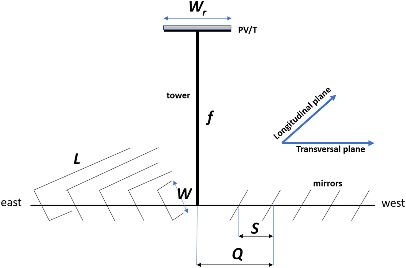
Theoretical configuration of the LFR system (Calik and Firat 2021).
Unless the solar hour angle is 90°, the sun is at the equinoxes, and the system is positioned at the equator (latitude φ = 0°), fixed and single axis tracking systems will undoubtedly encounter cosine effects (Calik and Firat 2021).
The lateral cosine effect, also known as the transversal cosine effect, is influenced by the transversal angle of solar incidence θ i . This angle is determined by the transversal solar altitude angle α T and the angle β i as shown in Figure 2.

Geometrical parameters on the transversal plane of the system (Calik and Firat 2019).
The geometrical parameters on the transversal plane of the system is calculated as the following (Calik and Firat 2019);
The angle β i is calculated by Q i and f as follows;
The value of angle α T can be determined by utilizing solar azimuth γ s and solar altitude angle α s as provided in Eq. (3):
The transversal cosine loss is then defined for a single mirror as following;
Thus, the total transversal cosine loss for all mirror can be computed using Eq. (5) as follows:
where N is the number of the mirrors in the considered system.
The end loss, also known as the longitudinal cosine loss, results in certain areas of the receiver being unilluminated. This loss is determined by the longitudinal angle at which solar radiation strikes the receiver, denoted as θ L ;
where θ is the solar incident angle which is defined as following;
φ is the latitude of the system location and the solar declination angle and the solar hour angle are defined as below respectively;
d is the day number of the year and t is the local solar hour. The longitudinal cosine loss for one mirror is then calculated by the Eq. (10).
Hence, the total longitudinal cosine loss is calculated as;
It is evident that the transverse and longitudinal cosine losses provide comprehensive details about the sun’s placement in the atmosphere, the solar energy in the area, and the mirror’s alignment with respect to the sun’s location, as demonstrated by Eqs. (1)–(11).
The mirror shading loss (L m ), the receiver shading loss (L r ), the edge loss (L e ), and the optical efficiency (η op ) can be determined by utilizing the system structural parameters such as mirror width (W), gap between adjacent mirrors (S), transversal (L T ), and longitudinal (L L ) without requiring any supplementary calculations (Calik and Firat 2021).
3 Energy and exergy analysis of the system
A series of flat mirrors are positioned in a consecutive manner in the LFR setup. The mirrors reflect sunlight and concentrate it onto a designated receiver at a particular elevation, as depicted in Figure 3. Consequently, the fluid inside the receiver is heated and can be utilized subsequently.
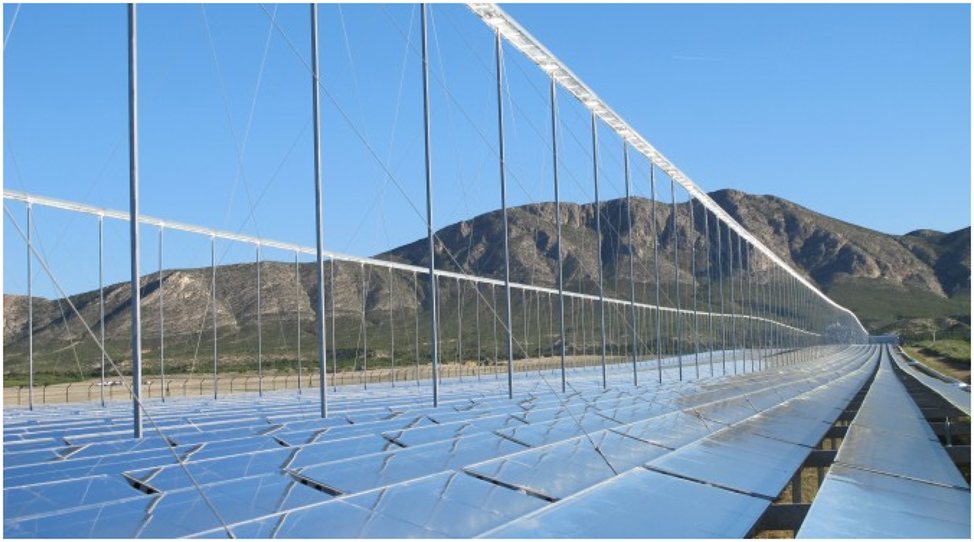
Linear Fresnel collector array, 1.4 MW PE1 plant in Murcia, Spain (Reve 2012).
The thermal receiver of a conventional LFR system is swapped out in present study for a PV/T panel in order to create a CPV/T system, as shown in Figure 4.

A CPV/T system using LFRs with PV/T receiver (Calik and Firat 2021).
Figure 5 introduces a typical perspective of the PV/T panel used in the study.

A representative image of the PV/T receiver.
The examined LFR-CPV/T arrangement comprises a combined sum of 10 mirrors, divided equally with 5 mirrors on each side of the collector region. While it is acknowledged that tracking in an LFR setup may not yield a flawless reflection (Mathur, Kandpal, and Negi 1991), this analysis assumes that all computations are executed with mirrors that follow the sun’s hourly position on the “representing day” of the month. Table 1 presents the technical details of the LFR system under consideration.
Technical properties of the LFR system.
| Property | Value |
|---|---|
| #Of Mirrors, N | 10 |
| Mirror length, L | 3 m |
| Mirror width, W | 0.4 m |
| Gap between the adjoint mirrors | 0.2 m |
| Receiver height, f | 3.31 |
| Reflectivity of mirrors in full spectrum, ρ | 98 % |
Despite the proposal of utilizing multi-junction solar cells for concentrated sunlight, solar cells made of polycrystalline or monocrystalline silicon (p-Sci, m-Si) can also be employed for sunlight that is relatively low in concentration. Consequently, this research considered a receiver part of the system that is composed of a high-efficiency photovoltaic panel made of monocrystalline silicon with an efficiency rate of 19.6 % (Mulligan et al. 2023; Sunpower X-Series Solar Panels 2023). The solar panel’s specifications are presented in Table 2, following standard test conditions (STC) AM1.5, 1000 W/m2, at an ambient temperature of 25 °C.
Technical properties of the PV panel.
| Property | Value |
|---|---|
| Length | 3 m |
| Width | 0.4 m |
| PV area, A pv | 1.2 m2 |
| Efficiency, η nom | 19.6 % |
| Emissivity of panel, ε | 98 % |
| Open circuit voltage, V oc | 0.727 V |
| Rated current density, J sc | 400 A/m2 |
| Fill factor | 0.812 |
| Power temperature coefficient, β | −0.29 %/°C |
To prevent any losses at the receiver’s end, the optical optimization calculations were performed according to Eqs. (10)–(15), and a width of 0.4 m was chosen. It was considered only the direct solar radiation in the calculations, as the mirrors are in opposite direction to the ground, making the contribution of diffuse radiation negligible.
The system described in this document is assumed to be located in Istanbul, Turkey. Istanbul experiences an average daily solar radiation of 4.18 kWh/m2 and receives approximately 7.5 h of sunlight per day throughout the year. Figure 6 depicts Istanbul’s relatively limited solar radiation and insolation hours, which can be attributed to its geographical coordinates of 41.0082° N and 28.9784° E.

The average daily global solar radiation and insolation hours in Istanbul (General Directorate of Energy Affairs. GEPA 2023).
Table 3 provides the weather information for Istanbul, including the average daily solar energy and the amount of concentrated energy reflected onto the receiver.
Monthly average daily solar energy, weather data for Istanbul, reflected concentrated energy, and the concentration ratio (CR).
| Month | Instant rad., E DNI , (W/m2) | Av. sunshine hours in a day, sh, (h/d) | Av. ambient temp., T a (°C) | Av. wind speed, v, (m/s) | Inlet temp., T in, (°C) | Instant reflected radiation, E r (W/m2) |
|---|---|---|---|---|---|---|
| January | 491.33 | 3.46 | 6.00 | 4.81 | 10.20 | 3521.25 |
| February | 493.12 | 4.43 | 6.10 | 4.81 | 9.00 | 3534.08 |
| March | 671.05 | 5.32 | 7.70 | 4.36 | 9.50 | 4809.26 |
| April | 655.18 | 6.85 | 12.00 | 4.03 | 11.80 | 4695.52 |
| May | 621.95 | 8.61 | 16.70 | 3.97 | 15.40 | 4457.37 |
| June | 549.14 | 10.51 | 21.40 | 4.28 | 19.20 | 3935.56 |
| July | 516.70 | 11.17 | 23.80 | 4.78 | 21.90 | 3703.07 |
| August | 508.83 | 10.14 | 23.80 | 4.78 | 22.90 | 3646.67 |
| September | 552.55 | 7.83 | 20.10 | 4.92 | 22.40 | 3960.00 |
| October | 609.00 | 5.22 | 15.70 | 4.36 | 19.80 | 4364.55 |
| November | 523.25 | 3.85 | 11.70 | 4.25 | 16.90 | 3750.01 |
| December | 516.89 | 2.96 | 8.20 | 4.83 | 13.20 | 3704.43 |
3.1 Energy analysis of the system
Roughly η nom E r and η nom E DNI are the amounts of electrical energy produced by the lower and upper PV panels respectively, from the reflected energy. The remaining (1−η nom )E r and (1−η nom )E DNI of the reflected energy on to bottom panel and incoming energy onto the top panel are transformed into thermal energy. Figure 7 illustrates the heat transfer process in the collector panel.

Heat transfer mechanisms in PV/T receiver.
The mathematical descriptions of the heat transfer mechanism for both sides of the receiver are given as following. To obtain the PV and absorber temperatures T 1, T ab1, T 2, T ab2 respectively;
where h v is the convective heat transfer coefficient of air which is calculated as below (Cole and Sturrock 1977);
T a is the ambient temperature, T in is the water inlet temperature, h w is heat transfer coefficient of water under laminar flow conditions, ε is the emissivity of PV surface, σ is the Stefan–Boltzmann constant, R is the thermal resistance in PV and absorber layers which is calculated as;
where, k pv thermal conductivity, L pv thickness of PV layer and, k ab thermal conductivity, L ab thickness of absorber layer.
Then, the water output temperature due to top and bottom absorber layers is calculated as following respectively;
Hence, the water output temperature is calculated as;
The daily thermal energy gained is then calculated as follows:
In the calculations, the surface area of all layers is assumed same as PV area of A pv .
The parameters given in Eqs. (15–25) are expressed in Tables 4 and 5.
Thermal and mechanical properties of the receiver.
| Property | Thickness, L, (m) | Heat transfer coefficient, k, h |
|---|---|---|
| PV panel, pv | 0.002 | 148 W/mK |
| Copper absorber, abs | 0.003 | 400 W/mK |
| Water (laminar), w | 0.005 | 50 W/m2K |
Flow and thermal properties of water.
| Property | Value |
|---|---|
| Specific heat, c w | 4186 J/kgK |
| Mass flow rate,
|
0.02 kg/s |
The top and bottom PV temperatures after cooled down are calculated as following;
The instant power output of the PV panels at maximum power point for a given power densities E r and E DNI and at new temperatures T 1 and T 2 is calculated as following;
Thus, the daily total daily electrical energy is obtained as below;
The daily total incoming energy on both sides of the receiver is calculated as;
The daily thermal and electrical efficiency are calculated as they are in Eqs. (31) and (32) respectively;
If the electric power generation efficiency conversion factor of a conventional power plant is taken as 38 %, then the overall efficiency of the system is given as below (Cole and Sturrock 1977);
3.2 Exergy analysis of the system
Exergy analysis assesses how effectively solar energy is used. Exergy analysis can be used to boost a system’s effectiveness by identifying the causes and scope of irreversibility. Numerous studies have been done on the effectiveness of various systems in the commercial (Masjuki et al. 2006; Mohammadnejad et al. 2011), industrial (Hacihafizoglu 2011; Saidur, Khaliq, and Masjuki 2006; Saidur, Ahamed, and Masjuki 2010), residential (Saidur, Masjuki, and Jamaluddin 2007a) and transportation (Saidur et al. 2007b) sectors. Researchers like in Refs. (Ahamed, Saidur, and Masjuki 2011; Dikmen, Sencan, and Selbas 2011) have examined the refrigeration cycle’s exergy. Exergy analysis is also used in a variety of solar heating devices (Nwosu 2009; Shukla, Buddhi, and Sawhney 2009), solar water desalination (Gomri 2009), solar air conditioning and refrigeration systems (Koroneos, Nanaki, and Xydis 2010), solar drying processes (Celma and Cuadros 2009), and solar power generation (Suresh, Reddy, and Kolar 2010) applications.
It should go without saying that determining the exergy content of solar radiation is critical to determining how well systems convert energy from the Sun.
The general exergy balance for a CPV/T module can be written including exergy in, out and destroyed as following (Agrawal and Tiwari 2011);
where, exergy out is the sum of thermal and electrical exergy;
In the exergy in equation, Eq. (36), the maximum efficiency term used as suggested by Petela (2003).
In other words, the geometric factor, f H , of the heat reservoir introduced by Badescu (2014) was ignored in this study.
where, δ is the half-angle of cone subtending the sphere when viewed from observer, θ z is the zenith angle.
The exergy efficiency is given as following by modifying the definition in the Ref. (Yantovskii 1994);
where thermal and electrical exergy efficiencies are defined as below respectively;
4 Results
Thermal calculations are performed analytically and numerically using the finite element method (FEM). 109,654 mesh elements of tetrahedral and prismatic geometry are used to construct the system for numerical computation. The results were obtained by solving the heat transfer equation under laminar flow conditions in steady-state mode. The numerical method (FEM) is utilized to determine the system’s output temperature and then daily thermal energy. The analytical equations in Eqs. (28) and (29) are used to calculate the values for electrical energy. To ensure clear and straightforward interpretation of the numerical results obtained through the finite element method and presented in Table 6, it is recommended to refer to Figure 5, Tables 2 and 3, Figure 7, Eq. (20), as well as Tables 4 and 5. These visual representations, tables, and equations provide valuable insights for understanding the results effectively.
The electrical and thermal performance of the system.
| Month | Daily electrical energy, P T, (kWh/d) | Daily thermal energy Q T, (kWh/d) | Efficiency | |||
|---|---|---|---|---|---|---|
| Analytical results | FEM results | Thermal η T , (%) | Electrical η pv , (%) | Overall η cpv/T , (%) | ||
| 1 | 3.5 | 8.20 | 8.17 | 49.34 | 24.91 | 50.00 |
| 2 | 4.5 | 10.91 | 10.84 | 50.96 | 24.90 | 51.61 |
| 3 | 7.1 | 18.16 | 18.89 | 51.91 | 24.79 | 52.56 |
| 4 | 8.9 | 25.72 | 24.99 | 58.47 | 24.50 | 59.11 |
| 5 | 10.6 | 31.38 | 30.40 | 59.80 | 24.21 | 60.44 |
| 6 | 11.5 | 33.66 | 32.69 | 59.51 | 24.09 | 60.14 |
| 7 | 11.5 | 31.48 | 31.57 | 55.66 | 23.69 | 56.28 |
| 8 | 10.3 | 27.50 | 27.65 | 54.38 | 23.69 | 55.00 |
| 9 | 8.6 | 21.18 | 21.51 | 49.95 | 23.94 | 50.58 |
| 10 | 6.3 | 16.17 | 16.02 | 51.90 | 24.24 | 52.54 |
| 11 | 4.1 | 10.14 | 9.92 | 51.38 | 24.52 | 52.03 |
| 12 | 3.1 | 7.23 | 7.23 | 48.22 | 24.76 | 48.87 |
The daily electricity and heat energy efficiencies of the CPV/T panel utilizing the linear Fresnel reflector can be found in Table 6. Thermal computations are presented in Figure 8, illustrating both analytical and numerical outcomes.
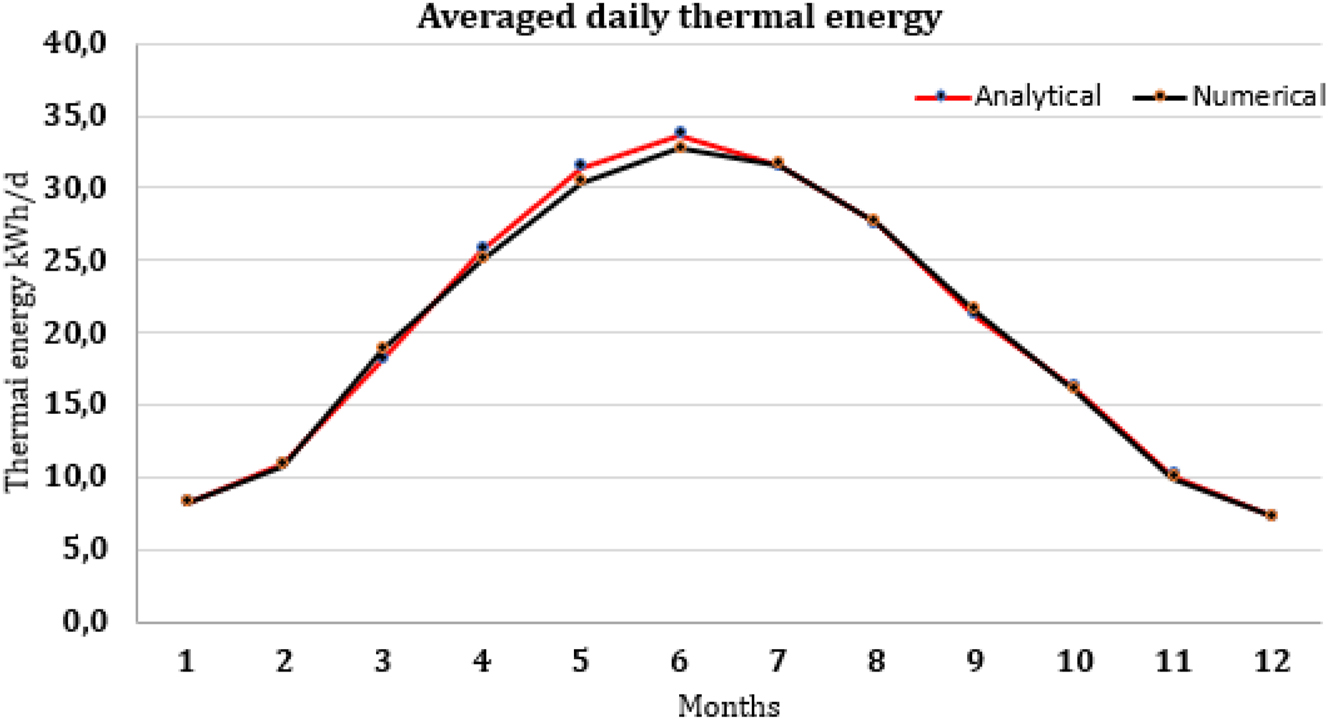
Obtained daily thermal energy from the CPV/T panel.
Incoming solar radiation, thermal and electrical exergy values and the overall exergy efficiency of the system are calculated as in Table 7.
Exergy values and overall exergy efficiency of the system.
| Months | Exergy in (kWh/d) | Thermal exergy (kWh/d) | Thermal exergy destruction (kWh/d) | Electrical exergy (kWh/d) | Electrical exergy destruction (kWh/d) | Overall exergy efficiency (%) |
|---|---|---|---|---|---|---|
| 1 | 15.59 | 7.82 | 0.40 | 3.27 | 0.88 | 50.75 |
| 2 | 20.03 | 10.38 | 0.53 | 4.20 | 1.14 | 52.39 |
| 3 | 32.72 | 17.28 | 0.88 | 6.86 | 1.82 | 53.36 |
| 4 | 41.09 | 24.45 | 1.27 | 8.62 | 2.15 | 60.05 |
| 5 | 48.97 | 29.81 | 1.58 | 10.29 | 2.42 | 61.43 |
| 6 | 52.71 | 31.94 | 1.72 | 11.09 | 2.54 | 61.15 |
| 7 | 52.68 | 29.86 | 1.62 | 11.09 | 2.31 | 57.24 |
| 8 | 47.10 | 26.08 | 1.41 | 9.91 | 2.07 | 55.93 |
| 9 | 39.53 | 20.10 | 1.08 | 8.31 | 1.84 | 51.41 |
| 10 | 29.08 | 15.36 | 0.81 | 6.11 | 1.45 | 53.38 |
| 11 | 18.44 | 9.64 | 0.50 | 3.87 | 0.97 | 52.84 |
| 12 | 14.02 | 6.88 | 0.35 | 2.94 | 0.77 | 49.61 |
The comparison of thermal and electrical energy and exergy values is given in Figure 9 and overall energy and exergy efficiencies in Figure 10.

The comparison of thermal and electrical energy and exergy values.

The comparison of overall energy and exergy efficiencies.
Although energy and exergy values have a slight variance, the exergy findings indicate the presence of some degree of exergy destruction in both the thermal and electrical components. This could be enhanced to achieve a better system performance.
5 Conclusions
In this study, a CPV/T system based on linear Fresnel reflectors (LFR) is evaluated in terms of energy and exergy. A PV/T system of 3 m length and 40 cm width is used as a receiver in a conventional LFR system.
In the specified solar irradiation circumstances, with an instantaneous average direct normal radiation of 559 W/m2 at the site, the system with 7.17 concentration ratio, produces an average of 271.23 kWh of electrical and 613.63 kWh of thermal energy per month. As the everyday usage of electricity remains below 7 kWh/d and the usage of thermal energy (to heat water and spaces) remains below 20 kWh/d per house in Turkey, the findings from the system indicate that a system of this size would suffice for household use. The outcome would be significantly noteworthy if the system is upscaled. Hence, because this kind of system is less expensive than a typical solar power system, it can be deemed a substitute source of energy in inconveniently situated regions.
However, examination of the system using exergy analysis reveals some degree of exergy destruction in the thermal and electrical components of the system. The system loses 1.01 kWh on average owing to thermal factors per day, and 1.70 kWh due to electrical factors. This indicates that the system is not operating at its maximum potential, as a significant amount of useful work is being lost.
Despite the system’s exergy efficiency being 54.96 %, which appears more favorable than its energy efficiency of 54.1 %, the exergy values of the thermal and electrical components reveal that enhancing the overall system performance can be achieved by minimizing both energy and exergy losses. This can be achieved by improving the efficiency of the system’s components, reducing energy waste, and optimizing the design and operation of the system.
-
Author contributions: Keziban CALIK: She completed her PhD thesis on “Proposal and Modeling of a Highly Concentrated Micro-Photovoltaic/Thermal Combined Hybrid Energy System” under my supervision. During her study, she published more than 5 scientific papers, attended 3 conferences, and obtained a patent for the resulting product. This article is also a continuation of her PhD research. She performed all the simulations in the present work. Coskun FIRAT: I built the backbone of the article myself, provided theoretical knowledge about the subject, reviewed all the results, and then drew a conclusion.
-
Research funding: There has been no any financial support for this work that could have influenced its outcome.
-
Conflict of interest statement: We wish to confirm that there are no known conflicts of interest associated with this publication. We confirm that the manuscript has been read and approved by all named authors and that there are no other persons who satisfied the criteria for authorship but are not listed. We further confirm that the order of authors listed in the manuscript has been approved by all of us. We understand that the Corresponding Author is the sole contact for the Editorial process (including Editorial Manager and direct communications with the office). He/she is responsible for communicating with the other authors about progress, submissions of revisions and final approval of proofs. We confirm that we have provided a current, correct email address which is accessible by the Corresponding Author.
References
Abbas, R., J. Muñoz-Antón, M. Valdés, and J. M. Martínez-Val. 2013. “High Concentration Linear Fresnel Reflectors.” Energy Conversion and Management 72: 60–8. https://doi.org/10.1016/j.enconman.2013.01.039.Search in Google Scholar
Agrawal, S., and G. N. Tiwari. 2011. “Energy and Exergy Analysis of Hybrid Micro-channel Photovoltaic Thermal Module.” Solar Energy 85: 356–70. https://doi.org/10.1016/j.solener.2010.11.013.Search in Google Scholar
Ahamed, J. U., R. Saidur, and H. H. Masjuki. 2011. “A Review on Exergy Analysis of Vapor Compression Refrigeration System.” Renewable and Sustainable Energy Reviews 15 (3): 1593–600. https://doi.org/10.1016/j.rser.2010.11.039.Search in Google Scholar
Badescu, V. 2014. “How Much Work Can Be Extracted from a Radiation Reservoir?.” Physica A: Statistical Mechanics and its Applications 410: 110–9. https://doi.org/10.1016/j.physa.2014.05.024.Search in Google Scholar
Calik, K., and C. Firat. 2019. “A Cost-Effective Theoretical Novel Configuration of Concentrated Photovoltaic System with Linear Fresnel Reflectors.” Journal of Polytechnic 22 (3): 583–9. https://doi.org/10.2339/politeknik.523704.Search in Google Scholar
Calik, K., and C. Firat. 2021. “Book Chapter VII – “A Comprehensive Optical Loss Analysis of a Linear Fresnel Reflector-Photovoltaic Hybrid System with Computer Aided Design.” In Engineering and Architecture Sciences Theory, Current Researches and New Trends 2021. Cetinje, Montenegro: IVPE Publisher.Search in Google Scholar
Celma, A. R., and F. Cuadros. 2009. “Energy and Exergy Analyses of OMW Solar Drying Process.” Renewable Energy 34 (3): 660–6. https://doi.org/10.1016/j.renene.2008.05.019.Search in Google Scholar
Chow, T. T., G. Pei, K. F. Fong, Z. Lin, A. L. S. Chan, and J. Ji. 2009. “Energy and Exergy Analysis of Photovoltaic–Thermal Collector with and without Glass Cover.” Applied Energy 86 (3): 310–6. https://doi.org/10.1016/j.apenergy.2008.04.016.Search in Google Scholar
Cole, R. J., and N. S. Sturrock. 1977. “The Convective Heat Exchange at the External Surface of Buildings.” Building and Environment 12 (4): 207–14. https://doi.org/10.1016/0360-1323(77)90021-x.Search in Google Scholar
Daneshazarian, R., E. Cuce, P. M. Cuce, and F. Sher. 2018. “Concentrating Photovoltaic Thermal (CPVT) Collectors and Systems: Theory, Performance Assessment and Applications.” Renewable and Sustainable Energy Reviews 81: 473–92. https://doi.org/10.1016/j.rser.2017.08.013.Search in Google Scholar
Del Col, D., M. Bortolato, A. Padovan, and M. Quaggia. 2014. “Experimental and Numerical Study of a Parabolic Trough Linear CPVT System.” Energy Procedia 57: 255–64. https://doi.org/10.1016/j.egypro.2014.10.030.Search in Google Scholar
Dikmen, E., A. Sencan, and R. Selbas. 2011. “Energetic and Exergetic Approach to Vapor Compression Refrigeration Cycle with Two-Stage and Intercooler for New Refrigerants.” Energy Education Science and Technology-Part A 26 (2): 205–19.Search in Google Scholar
Gakkhar, N., M. K. Soni, and S. Jakhar. 2020. “Experimental and Theoretical Analysis of Hybrid Concentrated Photovoltaic/thermal System Using Parabolic Trough Collector.” Applied Thermal Engineering 171: 115069. https://doi.org/10.1016/j.applthermaleng.2020.115069.Search in Google Scholar
General Directorate of Energy Affairs. GEPA. 2023. Solar Energy Potential Atlas in Turkey. https://gepa.enerji.gov.tr/MyCalculator/pages/34.aspx (accessed February 26, 2023).Search in Google Scholar
George, M., A. K. Pandey, N. A. Rahim, V. V. Tyagi, S. Shahabuddin, and R. Saidur. 2019. “Concentrated Photovoltaic Thermal Systems: A Component-By-Component View on the Developments in the Design, Heat Transfer Medium and Applications.” Energy Conversion and Management 186: 15–41. https://doi.org/10.1016/j.enconman.2019.02.052.Search in Google Scholar
Gomri, R. 2009. “Energy and Exergy Analyses of Seawater Desalination System Integrated in a Solar Heat Transformer.” Desalination 249 (1): 188–96. https://doi.org/10.1016/j.desal.2009.01.021.Search in Google Scholar
Hacihafizoglu, O. 2011. “Energy–exergy Analysis of Gas Turbine Cycle in a Combined Cycle Power Plant.” Energy Education Science and Technology-Part A 27 (1): 123–38.Search in Google Scholar
Heimsath, A., F. Cuevas, A. Hofer, P. Nitz, and W. J. Platzer. 2014. “Linear Fresnel Collector Receiver: Heat Loss and Temperatures.” Energy Procedia 49: 386–97. https://doi.org/10.1016/j.egypro.2014.03.042.Search in Google Scholar
Kasaeian, A., S. Tabasi, J. Ghaderian, and H. Yousefi. 2018. “A Review on Parabolic trough/Fresnel Based Photovoltaic Thermal Systems.” Renewable and Sustainable Energy Reviews 91: 193–204. https://doi.org/10.1016/j.rser.2018.03.114.Search in Google Scholar
Koroneos, C., E. Nanaki, and G. Xydis. 2010. “Solar Air Conditioning Systems and Their Applicability – an Exergy Approach.” Resources, Conservation and Recycling 55 (1): 74–82. https://doi.org/10.1016/j.resconrec.2010.07.005.Search in Google Scholar
Masjuki, H. H., M. A. Kalam, M. Syazly, T. M. I. Mahlia, A. H. Rahman, M. Redzuan, M. Varman, R. Saidur, and Y.h. Yau, et al.. 2006. “Experimental Evaluation of an unmodified Diesel Engine Using Biodiesel with Fuel Additive.” In IFOST 2006: 1st International Forum on Strategic Technology, Proceedings, 96–9. IEEE.10.1109/IFOST.2006.312257Search in Google Scholar
Mathur, S. S., T. C. Kandpal, and B. S. Negi. 1991. “Optical Design and Concentration Characteristics of Linear Fresnel Reflector Solar Concentrators-II. Mirror Elements of Equal Width.” Energy Conversion and Management 31 (3): 221–32. https://doi.org/10.1016/0196-8904(91)90076-u.Search in Google Scholar
Mohammadnejad, M., M. Ghazvini, F. S. Javadi, and R. Saidur. 2011. “Estimating the Exergy efficiency of Engine Using Nanolubricants.” Energy Education Science and Technology A: Energy Science and Research 27 (2): 447–54.Search in Google Scholar
Montes, M. J., C. Rubbia, R. Abbas, and J. M. Martínez-Valc. 2014. “A Comparative Analysis of Configurations of Linear Fresnel Collectors for Concentrating Solar Power.” Energy 73: 192–203. https://doi.org/10.1016/j.energy.2014.06.010.Search in Google Scholar
Mulligan, W. P., D. H. Rose, M. J. Cudzinovic, D. M. De Ceuster, K. R. McIntosh, D. D. Smith, and R. M. Swanson. Manufacture of Solar Cells with 21 % Efficiency. https://tayloredge.com/reference/Electronics/Photonics/HighEfficiencySolarCells.pdf (accessed March 11, 2023).Search in Google Scholar
Muthu Manokar, A., D. P. Winston, and M. Vimala. 2014. “Performance Analysis of Parabolic Trough Concentrating Photovoltaic Thermal System.” Procedia Technology 24: 485–91. https://doi.org/10.1016/j.protcy.2016.05.083.Search in Google Scholar
Nwosu, N. P. 2009. “Employing Exergy-Optimized Pin fins in the Design of an Absorber in a Solar Air Heater.” In Ht2009: Proceedings of the ASME Summer Heat Transfer Conference, Vol. 1, 271–7.10.1115/HT2009-88317Search in Google Scholar
Otterbein, R., W. A. Facinelli, and D. L. Evans. 1978. Combined Photovoltaic/Thermal System Studies. Cambridge, MA: NASA STI.Search in Google Scholar
Petela, R. 2003. “Exergy of Undiluted Thermal Radiation.” Solar Energy 74 (6): 469–88. https://doi.org/10.1016/s0038-092x(03)00226-3.Search in Google Scholar
Renno, C., and F. Petito. 2019. “Modelling of a Linear Focus Concentrating Photovoltaic and Thermal System for Different Load Scenarios of a Residential User.” Energy Conversion and Management 188: 214–29. https://doi.org/10.1016/j.enconman.2019.03.024.Search in Google Scholar
Saidur, R., A. H. A. Khaliq, and H. H. Masjuki. 2006. “Analysis of Energy and Exergy Use for Process Heating in the Industrial Sector of Malaysia.” International Journal of Exergy 3 (2): 119–49. https://doi.org/10.1504/ijex.2006.009041.Search in Google Scholar
Saidur, R., H. H. Masjuki, and M. Y. Jamaluddin. 2007a. “An Application of Energy and Exergy Analysis in Residential Sector of Malaysia.” Energy Policy 35 (2): 1050–63. https://doi.org/10.1016/j.enpol.2006.02.006.Search in Google Scholar
Saidur, R., M. A. Sattar, H. H. Masjuki, S. Ahmed, and U. Hashim. 2007b. “An Estimation of the Energy and Exergy efficiencies for the Energy Resources Consumption in the Transportation Sector in Malaysia.” Energy Policy 35 (8): 4018–26. https://doi.org/10.1016/j.enpol.2007.02.008.Search in Google Scholar
URL. Reve, 2012. https://www.evwind.es/2012/10/07/worlds-largest-linear-fresnel-solar-power-station-commences-operation/24364 (accessed March 11, 2023).Search in Google Scholar
Saidur, R., J. U. Ahamed, and H. H. Masjuki. 2010. “Energy, Exergy and Economic Analysis of Industrial Boilers.” Energy Policy 38 (5): 2188–97. https://doi.org/10.1016/j.enpol.2009.11.087.Search in Google Scholar
Sharaf, O. Z., and M. F. Orhan. 2015. “Concentrated Photovoltaic Thermal (CPVT) Solar Collector Systems: Part I – Fundamentals, Design Considerations and Current Technologies.” Renewable and Sustainable Energy Reviews 50: 1500–65. https://doi.org/10.1016/j.rser.2015.05.036.Search in Google Scholar
Shukla, A., D. Buddhi, and R. L. Sawhney. 2009. “Solar Water Heaters with Phase Change Material Thermal Energy Storage Medium: A Review.” Renewable and Sustainable Energy Reviews 13 (8): 2119–25. https://doi.org/10.1016/j.rser.2009.01.024.Search in Google Scholar
Sunpower X-Series Solar Panels. “Sunpower X-Series Solar Panels.” https://us.sunpower.com/sites/default/files/sunpower-x-series-commercial-solar-panels-x21-470-com-datasheet-524935-revb.pdf (accessed March 11, 2023).Search in Google Scholar
Suresh, M. V. J. J., K. S. Reddy, and A. K. Kolar. 2010. “4-E (Energy, Exergy, Environment, and Economic) Analysis of Solar Thermal Aided coal-fired Power Plants.” Energy for Sustainable Development 14: 267–79. https://doi.org/10.1016/j.esd.2010.09.002.Search in Google Scholar
Tripathia, R., G. N. Tiwari, T. S. Bhattia, and V. K. Dwivedi. 2017. “2-E (Energy-Exergy) for Partially Covered Concentrated Photovoltaic Thermal (PVT) Collector.” Energy Procedia 142: 616–23. https://doi.org/10.1016/j.egypro.2017.12.102.Search in Google Scholar
Vajedi, H., M. Dehghan, M. Aminy, A. Pourrajabian, and G. G. Ilis. 2022. “Experimental Study on an Air-Based Photovoltaic-Thermal (PV-T) System with a Converging Thermal Collector Geometry: A Comparative Performance Analysis.” Sustainable Energy Technologies and Assessments 52 (B): 102153. https://doi.org/10.1016/j.seta.2022.102153.Search in Google Scholar
Valizadeh, M., F. Sarhaddi, and M. M. Adeli. 2019. “Exergy Performance Assessment of a Linear Parabolic Trough Photovoltaic Thermal Collector.” Renewable Energy 138: 1028–41. https://doi.org/10.1016/j.renene.2019.02.039.Search in Google Scholar
Widyolar, B. K., M. Abdelhamid, L. Jiang, R. Winston, E. Yablonovitch, G. Scranton, D. Cygan, H. Abbasi, and A. Kozlov. 2017. “Design, Simulation and Experimental Characterization of a Novel Parabolic Trough Hybrid Solar Photovoltaic/thermal (PV/T) Collector.” Renewable Energy 101: 1379–89. https://doi.org/10.1016/j.renene.2016.10.014.Search in Google Scholar
Yantovskii, E. I. 1994. “Energy and Exergy Currents.” In Series: An Introduction to Exergonomics. NY: Nova Science Publishers.Search in Google Scholar
Yao, W., X. Kong, X. Han, Y. Wang, J. Cao, and W. Gao. 2022. “Research on the Efficiency Evaluation of Heat Pipe PV/T Systems and its Applicability in Different Regions of China.” Energy Conversion and Management 269: 116136. https://doi.org/10.1016/j.enconman.2022.116136.Search in Google Scholar
Zhang, L., D. Jing, L. Zhao, J. Wei, and L. Guo. 2012. “Concentrating PV/T Hybrid System for Simultaneous Electricity and Usable Heat Generation: A Review.” International Journal of Photoenergy, Special Issue 2012, https://doi.org/10.1155/2012/869753.Search in Google Scholar
© 2024 the author(s), published by De Gruyter, Berlin/Boston
This work is licensed under the Creative Commons Attribution 4.0 International License.
Articles in the same Issue
- Solar photovoltaic-integrated energy storage system with a power electronic interface for operating a brushless DC drive-coupled agricultural load
- Analysis of 1-year energy data of a 5 kW and a 122 kW rooftop photovoltaic installation in Dhaka
- Reviews
- Real yields and PVSYST simulations: comparative analysis based on four photovoltaic installations at Ibn Tofail University
- A comprehensive approach of evolving electric vehicles (EVs) to attribute “green self-generation” – a review
- Exploring the piezoelectric porous polymers for energy harvesting: a review
- A strategic review: the role of commercially available tools for planning, modelling, optimization, and performance measurement of photovoltaic systems
- Comparative assessment of high gain boost converters for renewable energy sources and electrical vehicle applications
- A review of green hydrogen production based on solar energy; techniques and methods
- A review of green hydrogen production by renewable resources
- A review of hydrogen production from bio-energy, technologies and assessments
- A systematic review of recent developments in IoT-based demand side management for PV power generation
- Research Articles
- Hybrid optimization strategy for water cooling system: enhancement of photovoltaic panels performance
- Solar energy harvesting-based built-in backpack charger
- A power source for E-devices based on green energy
- Theoretical and experimental investigation of electricity generation through footstep tiles
- Experimental investigations on heat transfer enhancement in a double pipe heat exchanger using hybrid nanofluids
- Comparative energy and exergy analysis of a CPV/T system based on linear Fresnel reflectors
- Investigating the effect of green composite back sheet materials on solar panel output voltage harvesting for better sustainable energy performance
- Electrical and thermal modeling of battery cell grouping for analyzing battery pack efficiency and temperature
- Intelligent techno-economical optimization with demand side management in microgrid using improved sandpiper optimization algorithm
- Investigation of KAPTON–PDMS triboelectric nanogenerator considering the edge-effect capacitor
- Design of a novel hybrid soft computing model for passive components selection in multiple load Zeta converter topologies of solar PV energy system
- A novel mechatronic absorber of vibration energy in the chimney
- An IoT-based intelligent smart energy monitoring system for solar PV power generation
- Large-scale green hydrogen production using alkaline water electrolysis based on seasonal solar radiation
- Evaluation of performances in DI Diesel engine with different split injection timings
- Optimized power flow management based on Harris Hawks optimization for an islanded DC microgrid
- Experimental investigation of heat transfer characteristics for a shell and tube heat exchanger
- Fuzzy induced controller for optimal power quality improvement with PVA connected UPQC
- Impact of using a predictive neural network of multi-term zenith angle function on energy management of solar-harvesting sensor nodes
- An analytical study of wireless power transmission system with metamaterials
- Hydrogen energy horizon: balancing opportunities and challenges
- Development of renewable energy-based power system for the irrigation support: case studies
- Maximum power point tracking techniques using improved incremental conductance and particle swarm optimizer for solar power generation systems
- Experimental and numerical study on energy harvesting performance thermoelectric generator applied to a screw compressor
- Study on the effectiveness of a solar cell with a holographic concentrator
- Non-transient optimum design of nonlinear electromagnetic vibration-based energy harvester using homotopy perturbation method
- Industrial gas turbine performance prediction and improvement – a case study
- An electric-field high energy harvester from medium or high voltage power line with parallel line
- FPGA based telecommand system for balloon-borne scientific payloads
- Improved design of advanced controller for a step up converter used in photovoltaic system
- Techno-economic assessment of battery storage with photovoltaics for maximum self-consumption
- Analysis of 1-year energy data of a 5 kW and a 122 kW rooftop photovoltaic installation in Dhaka
- Shading impact on the electricity generated by a photovoltaic installation using “Solar Shadow-Mask”
- Investigations on the performance of bottle blade overshot water wheel in very low head resources for pico hydropower
- Solar photovoltaic-integrated energy storage system with a power electronic interface for operating a brushless DC drive-coupled agricultural load
- Numerical investigation of smart material-based structures for vibration energy-harvesting applications
- A system-level study of indoor light energy harvesting integrating commercially available power management circuitry
- Enhancing the wireless power transfer system performance and output voltage of electric scooters
- Harvesting energy from a soldier's gait using the piezoelectric effect
- Study of technical means for heat generation, its application, flow control, and conversion of other types of energy into thermal energy
- Theoretical analysis of piezoceramic ultrasonic energy harvester applicable in biomedical implanted devices
- Corrigendum
- Corrigendum to: A numerical investigation of optimum angles for solar energy receivers in the eastern part of Algeria
- Special Issue: Recent Trends in Renewable Energy Conversion and Storage Materials for Hybrid Transportation Systems
- Typical fault prediction method for wind turbines based on an improved stacked autoencoder network
- Power data integrity verification method based on chameleon authentication tree algorithm and missing tendency value
- Fault diagnosis of automobile drive based on a novel deep neural network
- Research on the development and intelligent application of power environmental protection platform based on big data
- Diffusion induced thermal effect and stress in layered Li(Ni0.6Mn0.2Co0.2)O2 cathode materials for button lithium-ion battery electrode plates
- Improving power plant technology to increase energy efficiency of autonomous consumers using geothermal sources
- Energy-saving analysis of desalination equipment based on a machine-learning sequence modeling