Maximum power point tracking techniques using improved incremental conductance and particle swarm optimizer for solar power generation systems
-
Akwasi Amoh Mensah
 ,
Xie Wei
,
Xie Wei
 ,
Duku Otuo-Acheampong
and
Tumbiko Mbuzi
,
Duku Otuo-Acheampong
and
Tumbiko Mbuzi

Abstract
The generation of power from solar energy by using Photovoltaic (PV) systems to convert the irradiation of the sun into electricity has been adopted over the past years. However, the PV system’s P–V and I–V characteristics become unstable when solar irradiation and temperature change. In this paper, the incremental conductance (INC) has been improved using signals to measure the current and voltage from the PV systems directly which quickly changes with the environmental conditions, and the conventional particle swarm optimization (PSO) is modified so that under multiple shaded peak PV array curves with fast-changing solar irradiance and temperature, more power is extracted at a faster rate without any tracking failure at high-speed tracking of both individual maximum power point (IMPP) and global maximum power point (GMPP) under varying solar irradiance and temperature at a longer distance to enhance the power generated. The individual and global coefficients are also improved to change with multiple shaded peak PV array curves with fast-changing solar irradiance and temperature. DC-DC converter converts DC power from one circuit to another and DC-AC inverter converts DC power to AC power. Simulation was carried out in MATLAB Simulink with different solar irradiance and temperature whereby the conventional INC and PSO were compared with the proposed INC and PSO. An experiment was carried out for a whole day from 8 am to 5 pm to test the validity of the proposed algorithm and compared it with the conventional INC and PSO by using the solar irradiance and temperature received. From both the simulation and experimental results, the proposed INC and PSO performed better by attaining high power and tracking speed with stable output results than the conventional INC and PSO.
1 Introduction
The use of renewable energy has drawn much attention over the past years. Many people have adopted renewable energy to produce power as there is a higher demand for power supply since fossil fuels are expensive and cause environmental pollution. Renewable energy includes solar energy, biomass, wind energy, hydropower, and geothermal energy. In this paper, the focus was to use solar energy to generate power by using a PV system. Sunlight received will be directly converted into electricity by solar PV arrays. Solar irradiance and temperature influence the output characteristics of PV arrays by external factors, the maximum power point (MPP) of a PV array varies alongside these external factors. Therefore, the maximum power point tracking (MPPT) technique has been adopted to improve the efficiency of power generated by the PV array. Different traditional MPPT techniques such as perturb and observe, incremental conductance, and fuzzy logic control have been introduced (Bhos, Sayyad, and Nasikkar 2022; Devana et al. 2022; Ghasemi, Forushanis, and Parniani 2016; Loukriz, Haddadi, and Messalti 2016; Manoharan et al. 2021; Premkumar and Sowmya 2019; Ujgare, Goudar, and Kharadkar 2022). These techniques are simple to implement and perform well under constant solar irradiance and temperature, but under varying solar irradiance and temperature, although MPP is tracked, the output of the maximum power point tracked is reduced. Maximum power point technique based on an improved perturb and observation method has been proposed (Manoharan et al. 2021) to avoid false tracking of maximum power during fast changes in solar irradiation due to the wrong decision in the duty cycle. It enhances the current, voltage, and power attained. The incremental conductance method is used mostly due to its accuracy when there is a change in the environmental condition. It also has a high tracking peak power under fast-changing weather conditions. It can determine if the maximum power point has been reached by the MPPT. Nevertheless, it is complex to implement and has a low convergence speed to reach the global peak (Ahmed and Salam 2018; Farh and Ali Eltamaly 2020; Hong et al. 2019; Hernanz et al. 2020; Ilyas et al. 2018; Loukriz, Haddadi, and Messalti 2016; Motahhir et al. 2017; Zhu et al. 2018). The incremental conductance MPPT method has been modified in grid-connected PV systems (Mishra and Tiwari 2021). The method presents the incremental conductance method being combined with an integral regulator to improve the maximum power point tracking effectiveness. The results of the method presented show that MPPT was accurately tracked because the integral regulator increases the power to its maximum level but this proposed method uses a lot of sensors which makes the operation difficult, also when some of the sensors stop working, it affects the whole MPPT process. The incremental conductance method is modified to track maximum power at a faster change in solar irradiance and temperature. The duty cycle which is the output of the maximum power point tracker is increased to enhance the output generated power but the method speed rate of tracking voltage and current from PV systems is low (Motahhir et al. 2018). These traditional MPPT methods are also unable to track the global maximum power point (GMPP) which affects the output power generated leading to a low tracking speed rate and a decrease in output generated power. To solve this problem, different algorithms such as particle swarm optimization (PSO) algorithm, firefly algorithm, bat algorithm, shuffled frog leap algorithm, artificial fish swarm algorithm, and ant colony optimization algorithm has been proposed (Access et al. 2021; Akwasi et al. 2022; Akwasi and Xie 2022; Duku et al. 2022; Eltamaly, Farh, and Al-Saud. 2019; Liao et al. 2020; Mao et al. 2016; Pilakkat and Kanthalakshm 2019; Premkumar et al. 2019, 2021, 2022; Premkumar and Sumithira 2018; Priyadarshi et al. 2019; Sridhar, Dash, and Vishnuram 2017; Yetayew, Jyothsna, and Kusuma 2016). From the literature, different algorithms have been used. A bio-inspired whale optimization for effective maximum power point tracking under partially shaded solar photovoltaic systems has been proposed by reinitializing the optimization process when there is a shading pattern by the PV system (Premkumar and Sowmya 2019).
Particle swarm optimization (PSO) is used mostly due to its fast-tracking method, and easy and simple implementation model (Eltamaly et al. 2020; Li et al. 2019; Manickam et al. 2016; Renaudineau et al. 2015). However, they often converge to local optimization whereby they are unable to locate the global maximum power point (GMPP). The overall distribution particle swarm optimization MPPT algorithm for photovoltaic systems proposes a method that can search and find the GMPP accurately and rapidly by locating the vicinity of the GMPP region (Li et al. 2019). This method produces an accurate result, however, the speed rate of tracking the maximum power is low. A novel adaptive particle swarm optimization strategy for PV maximum power point tracking under dynamic partial shading has been proposed (Eltamaly et al. 2020) with two classified conditions tested. The first condition is to check when the global peak changes its location and value quickly and the second condition is to check when the global peak changes its value slowly and remains at the initial position. These two conditions are tested by reinitializing the particles. The global peak was attained. However, the result is achieved when the global peak is constant. The change in the global and local peaks wasn’t tested. Also, the algorithms have been tested in many different areas from the literature (Kumar, Singh, and Panigrahi 2022; Kumari, Kumar, and Panigrahi 2022; Kumar and Panda, 2022a, 2022b; Saha, Kumar, and Panda 2022; Siu, Kumar, and Panda 2022). A model voltage sensorless-based predictive control (VSPC) scheme for continuous and quick maximum power harvesting (MPH) from photovoltaic (PV) array for solar-powered has been proposed (Kumar, Singh, and Panigrahi 2022). The proposed VSPC is used to control the PV array to detect the time and remove voltage sensors which enhances the tracking speed and improves the change in the environmental conditions. A maximum power point tracking algorithm based on parabolic curve-fitting with the hill climbing method has been proposed to extract maximum power from the PV array under different environmental conditions.
In this paper, PSO is modified so that under multiple shaded peak PV array curves with fast-changing solar irradiance and temperature, more power can be extracted at a faster rate without any tracking failure. Also, at a high-speed tracking of both individual maximum power point (IMPP) and global maximum power point (GMPP) under varying solar irradiance and temperature at a longer distance to enhance the power generated. The individual and global coefficients are also improved to change with multiple shaded peak PV array curves with fast-changing solar irradiance and temperature. Also, due to the complexity of the implementation and low convergence speed to reach the global peak of the incremental conductance method, the algorithm has been improved whereby the maximum power point is tracked using signals to measure the current and voltage from the PV systems directly which quickly changes with the environmental conditions with fast speed. This proposed method is easy to implement as the signal detects and changes when there is a change in environmental conditions. The algorithm was connected to other components such as DC to DC converter and DC to AC inverter to help obtain the output power generated.
The sections of this paper are as follows: Section 2 discusses the modeling of a PV module and array. Section 3 describes maximum power point tracking algorithms. In Section 4, the proposed control design is explained. Section 5 presents the control design and simulation results in MATLAB Simulink. Section 6 discusses the experimental design. Section 7 is the conclusion.
2 Photovoltaic system model
Figure 1 shows the equivalent circuit diagram of a PV cell. A PV cell consists of a current source and a diode connected with series and shunt resistances. The mathematical model of a PV cell can be expressed as:where, I is the output current of the PV cell,
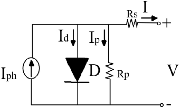
PV cell diagram.
The modeled PV cell has been simulated in MATLAB Simulink. Figure 2(a) and (b) show the I–V and P–V characteristics curves of a PV cell with different solar irradiances between 300 W/m2 to 1000 W/m2 at a constant temperature of 25 °C. Figure 3(a) and (b) show the I–V and P–V characteristics curves of a PV cell with different temperatures between 25 °C and 55 °C at a constant solar irradiance of 1000W/m2. At higher temperatures, the output voltage of the PV cell is decreased which decreases the output power.
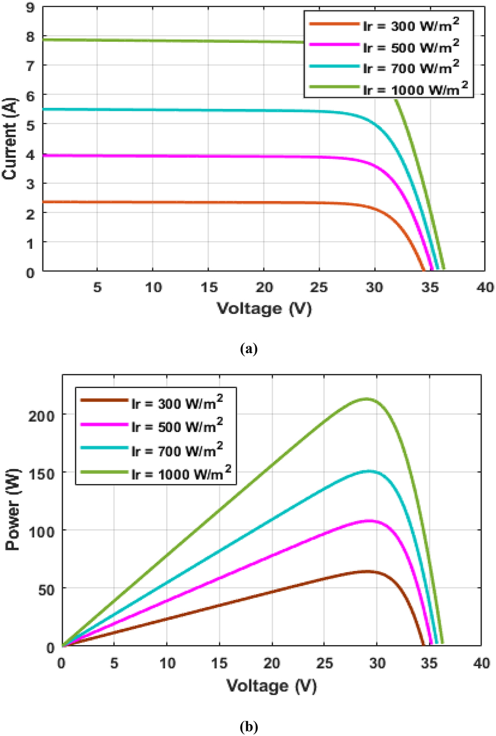
PV cell characteristics curves with different solar irradiance and constant temperature. (a) I–V characteristics curves of a PV cell with different solar irradiance and constant temperature. (b) P–V characteristics curves of a PV cell with different solar irradiance and constant temperature.
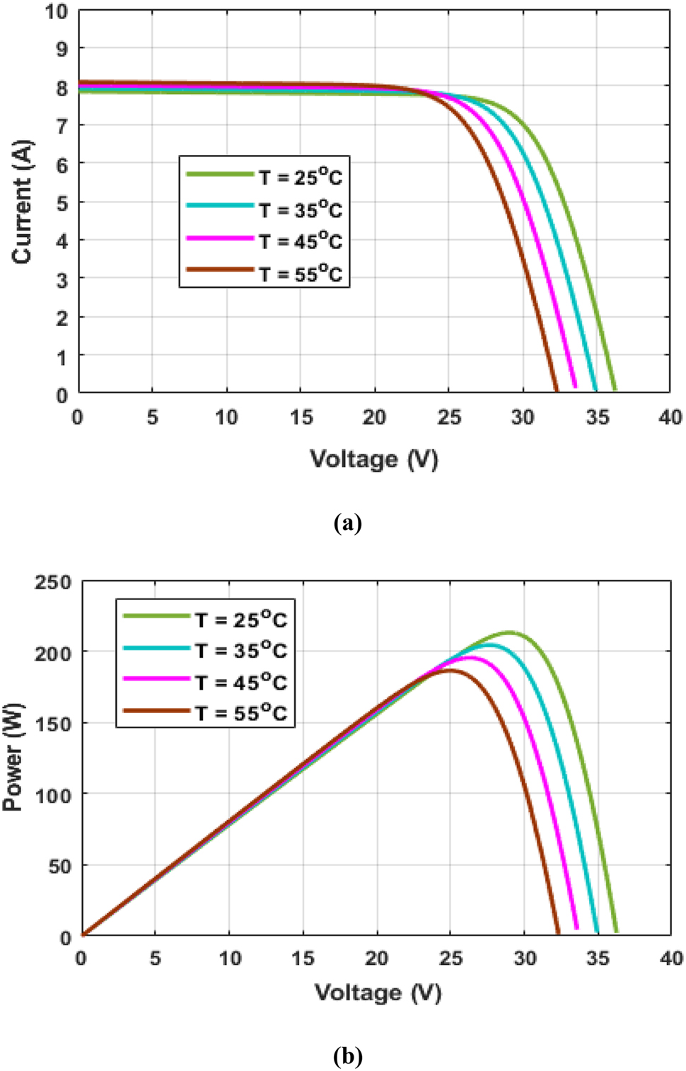
PV cell characteristics curves with constant solar irradiance and different temperature. (a) I–V characteristics curves of a PV cell with constant solar irradiance and different temperatures. (b) P–V characteristics curves of a PV cell with constant solar irradiance and different temperatures.
3 Proposed maximum power point tracker
Maximum power point tracking is the approach to enhance the maximum power output of the PV array. When there is variation in solar irradiance and temperature, MPPT maintains output power from the PV array to improve stability and accuracy. The two maximum power point tracking techniques introduced are incremental conductance and particle swarm optimization. These techniques help to improve the efficiency of the current and voltage of the PV array. The duty cycle is the MPPT’s output which is transferred to the DC-DC converter switch.
3.1 Proposed incremental conductance
The incremental conductance method measures the output voltage and current from the PV array. The output power is then calculated. This method proposes that the slope of the power curve of the PV panel is zero at MPP, positive to the left, and negative to the right at MPP (Ilyas et al. 2018). Therefore, the method can be expressed mathematically as:
The change in power, voltage ad current is achieved as:
The change in power and voltage at MPP on different sides are:
when,
Then,
The change in current and voltage at MPP on different sides are:
The method is improved whereby current and voltage are measured from the PV system using a signal. The signal directly measures the voltage and current from the PV system. The power is then calculated. k is the interval at which current, voltage, and power are measured and calculated in (12)–(14).
Here, the current is achieved between the interval of the PV array by using a signal that doubles the tracking speed.
The voltage is also achieved between the interval of the PV array by using a signal that doubles the tracking speed.
The power is a product of current and voltage and since the signal used doubles the tracking speeding, the power achieved also doubles.
At MPP, the change in voltage and current are obtained and measured. The output maximum power is calculated from the measured voltage and current.
The change in voltage and current by the signal from the PV array can be determined as
where, P mpp (K), V mpp (K), I mpp (K), ∆V mpp (K), ∆I mpp (K) are the power, voltage, current, change in voltage and current at MPP respectively, For this proposed method, when there is a change in solar irradiance and temperature, the change is detected, therefore, voltage and current change along hence extracting and measuring the MPP of the current and voltage from the PV array. When MPP is reached on the right side, the duty cycle increases while when MPP is reached on the left, the duty cycle decreases.
3.2 Proposed particle swarm optimization
The conventional PSO technique was proposed by Kennedy and Eberhart (Li et al. 2019). The technique was proposed by an observation made on environmental behaviors such as bird flocking and fish schooling. This MPPT algorithm is very easy to implement and has a fast convergence. When the output characteristics curves of PV arrays have a single peak value, the conventional PSO is fast and accurate but under multiple shaded peak curves, the weights in conventional PSO for each multi-peak curve must be readjusted and evaluated properly and if this is not performed, it leads to tracking failure in the weight results. In this paper, the conventional PSO is modified so that under multiple shaded peak PV array curves with fast-changing solar irradiance and temperature, more power can be extracted at a faster rate without any tracking failure. The individual and global coefficients are also improved to change with multiple shaded peak PV array curves with fast-changing solar irradiance and temperature. The proposed PSO method tracks the voltage at maximum power point based on the initial velocity and position of each particle randomly, where the number of particles and iterations are represented by i and k respectively. The fitness of each particle is evaluated. The individual best position (P besti) and the global best position (g besti) of the particles are detected. When the individual best position is greater than the global best position, the velocity and position of the particle will be continuously updated until the optimal solution is met. The output voltage of the PV array consists of a particle, when the number of particles continuously increases, velocity decreases which moves particles faster toward the position hence the output voltage increases which enhances the efficiency of output power produced at its maximum point. The movement of particles changes when there is a change in solar irradiance and temperature. The proposed PSO method can be expressed mathematically as:
The next position of the particles is
The next velocity is calculated when the individual best is achieved.
The next velocity is calculated when the global best position is achieved.
where v
i
and x
i
are the velocity and position of the particle i respectively, k is the iteration number, ω is the inertia weight, r
1 and r
2 are random variables with the interval [0, 1], and c
1 and c
2 are the individual and global coefficients respectively, P
besti and g
besti are the individual best position and global best position of the particle i respectively.
As the particles move to a position, the PV voltage V pv and PV current I pv can be measured. The fitness value P pv of the particle i is calculated. The iteration number increases the speed of the particle to search for the global best position in a long distance and the individual best position in a shorter distance. To increase the speed, the PSO method is improved where ω is decreased by increasing the iteration number k. The movement of particles becomes faster and approaches MPP to track more MPP accurately.
The inertia weight values can be calculated as
where,
Substituting the iteration number with maximum and minimum iteration, we can get.
where, ω max and ω min are the maximum and minimum inertia weight values, k is the iteration number, k max and k min are the maximum and minimum iteration numbers respectively.
The values of c 1, c 2, r 1 and r 2 affect the speed of the individual best position P best and global best position g best of the particle. r 1 and r 2 are random variables with the interval [0, 1], and c 1 and c 2 are the individual and global coefficients respectively.
The fitness of the particles is evaluated. Individual and global best positions are detected. when,
The method is updated. The condition is satisfied when the individual and global best positions are equal.
P besti and g besti are the individual best position and the global best position.
When the fitness of each particle is calculated. i is greater than N. Then i is equal to i plus 1. If k is equal to k plus 1, then the criteria are not met, and the number of particles should be updated.
When the number of particles is updated, the voltage and current values are obtained at MPP. The speed stability and accuracy are enhanced.
The output maximum power point of current is obtained as
The output maximum power point of voltage is obtained as
We can derive the maximum output power to be:
where,
4 Proposed control design
Figure 4 shows the proposed control design. Solar irradiance and temperature are the input sources of the PV array which was used in the operation of the system. Two MPPT algorithms; incremental conductance and particle swarm optimization were used to trace and extract maximum power. DC-DC converter and DC-AC inverter were also used in the design to enhance the output produced power.
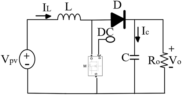
DC-DC converter circuit diagram.
4.1 DC-DC converter
DC-DC converter regulates the system’s input voltage to produce an efficient output voltage that can be supplied to the load since the output voltage across the load is higher than the input voltage from the PV array and is dependent on the rate at which inductor current changes. It also converts DC Power from one circuit to another circuit at a fixed voltage to a variable and vice versa. Capacitors are used to reduce the voltage ripple that is sent to the DC-AC inverter since too many ripples cause voltage instability. The duty cycle from MPPT is maximized when sent to the DC-DC converter switch. The output current also increases when transferred to the DC-DC converter switch. Figure 5 shows the DC-DC converter circuit diagram.
The parameters in Figure 5 defined as where V pv is the input voltage from the PV system, V o is the output voltage, DC is the duty cycle, D is the diode, I L is the inductor current, I C is the capacitor current, R O is the resistor, L is the inductor, C is the capacitor, M is MOSFET.
DC-AC inverter circuit diagram.
From Figure 5, the input voltage from the PV system is calculated as
where V pv is the input voltage from the PV system, V o is the output voltage, DC is the duty cycle, D is the diode.
According to Kirchhoff’s voltage law, the input voltage must be equal to the sum of the output voltage across the resistance, capacitor, and inductor. The differential can be expressed with t as
where, R O is the resistor, L is the inductor, C is the capacitor
When the converter operates, t is between the interval 0 < t < dT current and voltage are
when the converter stops operating, t is between the interval dT< t < T current and voltage are
I L is the inductor current, I C is the capacitor current.
4.2 DC-AC inverter
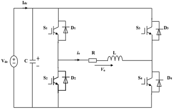
DC-AC inverter converts DC to AC to be supplied to the load for use since the current produced from the PV array is DC. The load supplies AC power and enhances the output AC power generated. It generates and also controls the output AC voltage to the grid. It allows PV generation to be connected to the grid and controls the power supplied to the grid. The inverter establishes a connection between the PV array and AC power supplied to the grid since the power generated by the PV array is DC power. Figure 6 shows the DC-AC inverter circuit diagram.
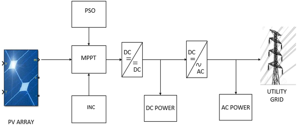
Proposed control design.
The parameters in Figure 6 defined as where V dc is the DC voltage, V o is the output voltage, C is the capacitor, L is the inductor, R is the resistor, I dc is the current from the DC source, I o is the output current.
The current from the DC source can be calculated as
From the inverter circuit diagram, we can obtain the voltage from DC to be
when the inverter operates, t is between the interval 0 < t < dT current and voltage are
when the inverter stops operating, t is between the interval dT < t < T current and voltage are
5 Simulation results and discussion
To test the effectiveness of the proposed control design, an experiment was carried out in MATLAB Simulink software (Figure 7). The proposed incremental inductance and particle swarm optimization MPPT methods were tested to produce an accurate output power for the grid Table 1 shows the parameters of the PV array used during the simulation process.
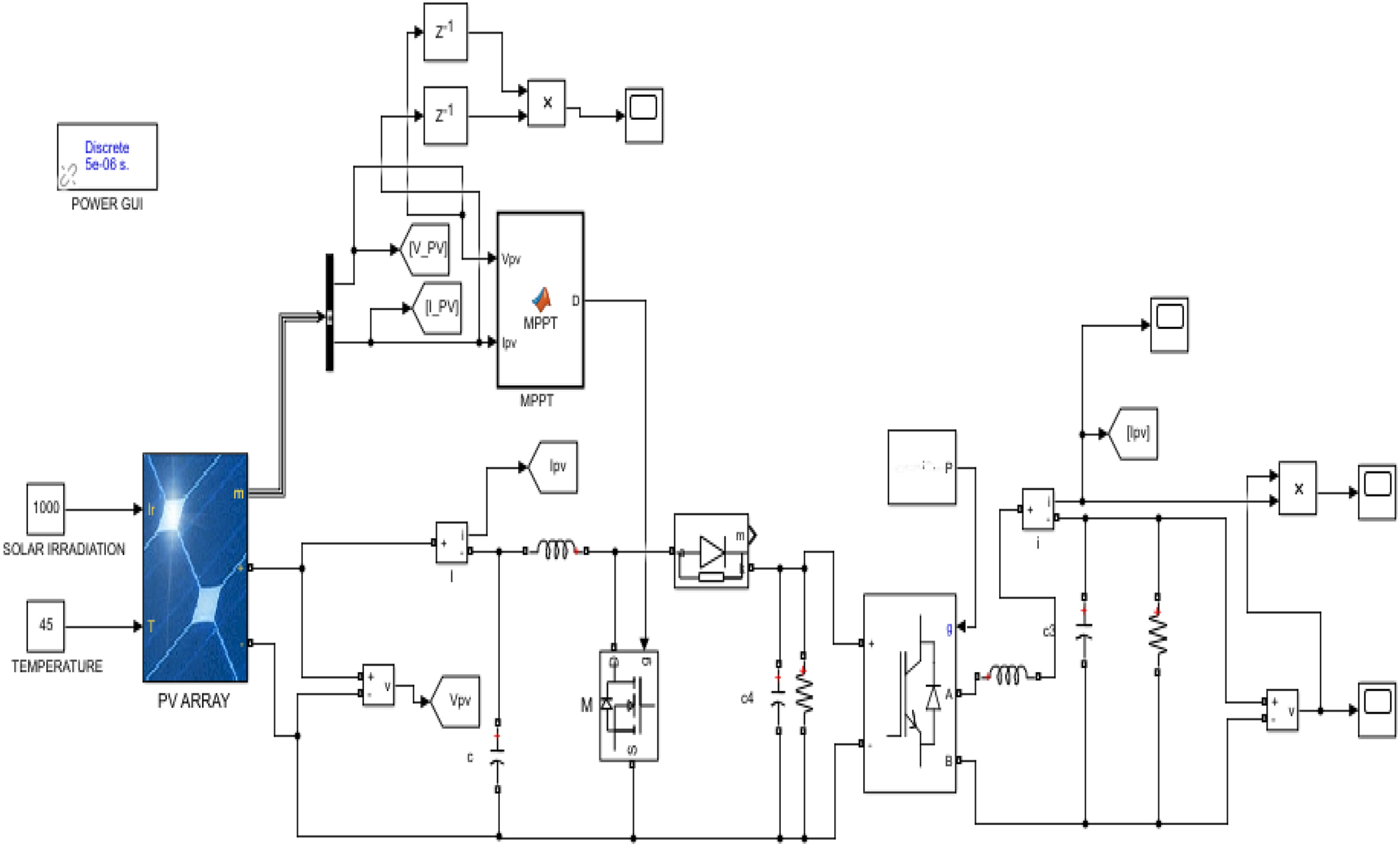
MATLAB simulink design.
Parameters of PV array.
| Description | Rating |
|---|---|
| Maximum power (P max) | 37.08 W |
| Voltage at maximum power (V mp) | 16.56 V |
| Current at maximum power (I mp) | 2.25 A |
| Open circuit voltage (V oc) | 21.24 V |
| Short circuit current (I sc) | 2.55 A |
| Total number of cells in series (Ns ) | 36 |
| Total number of cells in parallel (Np ) | 1 |
Figure 8(a)–(c) shows the current, voltage, and power produced by the incremental conductance MPPT method at solar irradiance of 700 W/m2 with a temperature of 25 °C at a time interval of 1–10 s. At the initial stage for current and power tracking, the rapid change in the environmental condition was unstable which affects the current but later became stable at 0.2 s with a current of 15.9 A and power of 2450 W which shows the fast-tracking and changing speed of the proposed INC. The voltage performed well as it increases from 0 V to 155 V with the change in the conditions and quickly becomes stable at 0.1 s.
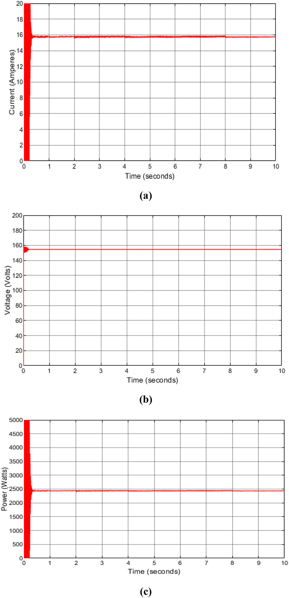
Incremental conductance output current, voltage and power produced. (a) Incremental conductance current produced at solar irradiance of 700 W/m2 with a temperature of 25 °C. (b) Incremental conductance voltage produced at solar irradiance of 700 W/m2 with a temperature of 25 °C. (c) Incremental conductance power generated at solar irradiance of 700 W/m2 with a temperature of 25 °C.
Figure 9(a)–(c) shows the current, voltage, and power produced by the particle swarm optimization MPPT method at solar irradiance of 700 W/m2 with a temperature of 25 °C at a time interval of 1–10 s. At the initial stage current and power tracking speed was quite slow and the stability was being maintained gradually when changing with the environmental conditions but few seconds, it changed quickly and the result shows that the output current and power was very high generating a power of 4850 W which shows the great performance of the proposed PSO. The voltage performed well as it was stable and moved from 0 V to 350 V as it increased with the change in the conditions.
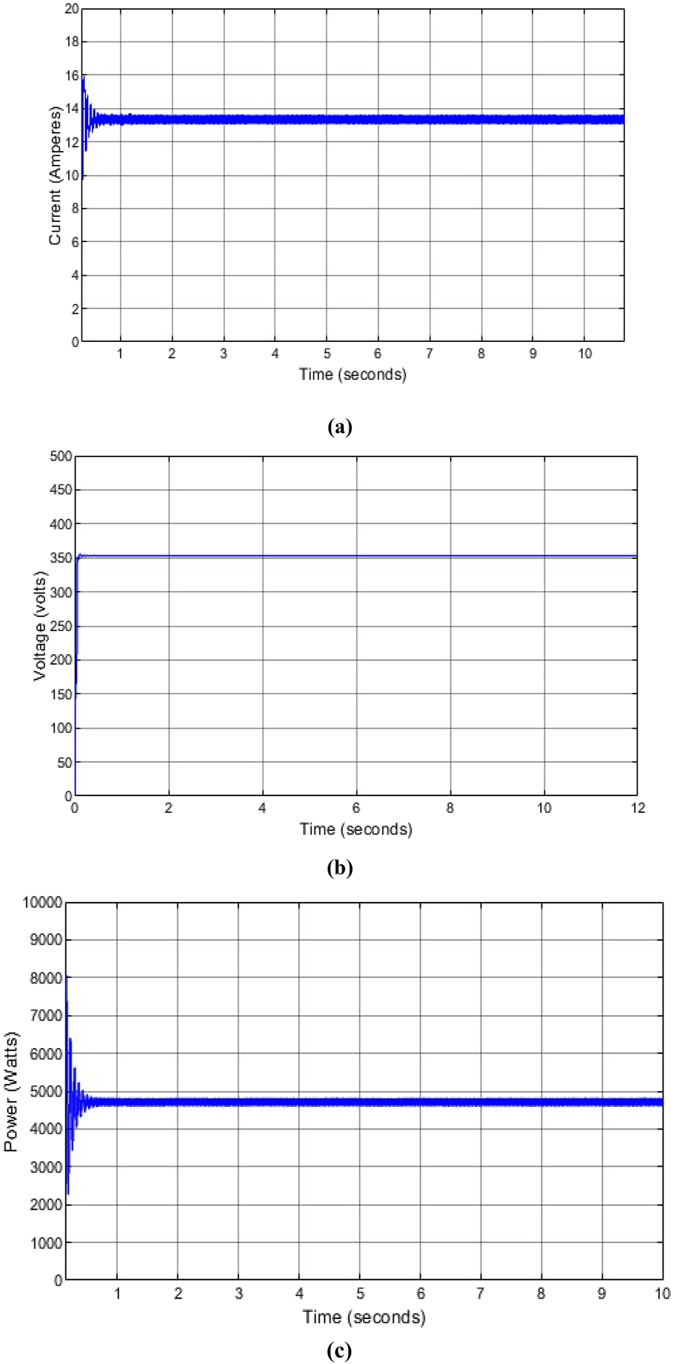
Particle swarm optimization output current, voltage and power produced. (a) Particle swarm optimization current produced at solar irradiance of 700 W/m2 with a temperature of 25 °C. (b) Particle swarm optimization voltage produced at solar irradiance of 700 W/m2 with a temperature of 25 °C. (c) Particle swarm optimization power generated at solar irradiance of 700 W/m2 with a temperature of 25 °C.
From the results obtained, the incremental conductance produced an output current of 15.9 A which is higher than the particle swarm optimization output current of 13.9 A. However, the current speed rate of incremental conductance is slow which causes higher instability and affects the output current generated while the particle swarm optimization method speed is high and stable. The particle swarm optimization method enhances the output voltage and so more voltage is produced at a faster speed than the incremental conductance method. When the output voltage increases, the output power generated also increases. When the tracking speed is high, the output power produced is higher and more power is produced in a shorter time interval.
Figure 10(a) and (b) show the power produced by the incremental conductance and particle swarm optimization MPPT method at solar irradiance of 900 W/m2 with a temperature of 25 °C at a time interval of 1–10 s. Figure 11(a) and (b) show the power produced by the incremental conductance and particle swarm optimization MPPT method at solar irradiance of 900 W/m2 with a temperature of 55 °C at a time interval of 1–10 s.
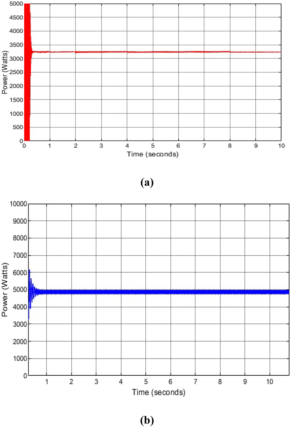
Incremental conductance and particle swarm optimization output power produced with change in solar irradiance. (a) Incremental conductance power generated at solar irradiance of 900 W/m2 with a temperature of 25 °C. (b) Particle swarm optimization power generated at solar irradiance of 900 W/m2 with a temperature of 25 °C.
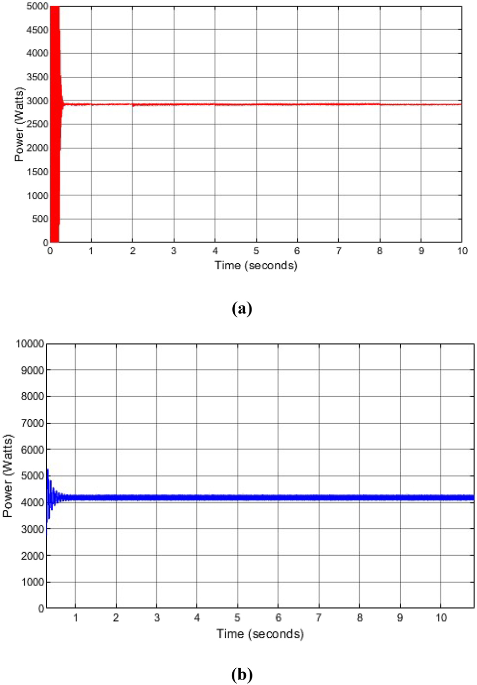
Incremental conductance and particle swarm optimization output power produced with change in temperature. (a) Incremental conductance power generated at solar irradiance of 900 W/m2 with a temperature of 55 °C. (b) Particle swarm optimization power generated at solar irradiance of 900 W/m2 with a temperature of 55 °C.
From Figure 8(c) and 10(a) of the INC and Figure 9(c) and 10(b) of the PSO generated power, when solar irradiance is increased from 700 W/m2 to 900 W/m2 with temperature of 25 °C, more power is generated. At 700 W/m2 of Figure 8(c) of INC and 9(c) of PSO, the output power generated at 10 s was 2450 W for INC and 4800 W for PSO and at 900 W/m2 of Figure 10(a) of INC and Figure 10(b) of PSO, the output power generated at 10 s was 3250 W for INC and 5000 W for PSO which indicates that when the solar irradiance increases, the output power increases and vice versa. In Figure 10(a) and (b) and Figure 11(a) and (b), when the temperature increases from 25 °C to 55 °C with solar irradiance of 900 W/m2, the power generated decreases. At 25 °C the output power generated for INC and PSO at 10 s were 3500 W and 5000 W respectively, and at 55 °C the output power generated for INC and PSO at 10 s were 2900 W and 4200 W respectively, which indicates that when the temperature increases, the output power decreases and vice versa. This is because at higher solar irradiance the output voltage increases but at higher temperatures, the output voltage decreases. When solar irradiance increases, the tracking speed rate becomes faster from the results obtained.
Tables 2 –5 shows the output generated current, voltage, power, and tracking time with different solar irradiance and temperature of 25 °C compared with incremental conductance, proposed incremental conductance, conventional PSO, and proposed PSO.
Result of output generated current with different solar irradiance and temperature of 25 °C.
| Output generated current (A) | ||||
|---|---|---|---|---|
| Solar irradiance (W/m2) | INC | Proposed INC | Conventional PSO | Proposed PSO |
| 600 | 11.6 | 12.4 | 12.2 | 13.8 |
| 800 | 14.2 | 15.6 | 15.3 | 16.5 |
| 1000 | 16.1 | 17.6 | 17.4 | 19.2 |
| 1200 | 17.6 | 19.8 | 19.1 | 21.8 |
| 1500 | 18.9 | 21.7 | 21.4 | 24.3 |
Result of output generated voltage with different solar irradiance and temperature of 25 °C.
| Output generated voltage (V) | ||||
|---|---|---|---|---|
| Solar irradiance (W/m2) | INC | Proposed INC | Conventional PSO | Proposed PSO |
| 600 | 227 | 291 | 241 | 348 |
| 800 | 272 | 346 | 332 | 373 |
| 1000 | 293 | 372 | 361 | 407 |
| 1200 | 321 | 394 | 386 | 436 |
| 1500 | 348 | 415 | 402 | 452 |
Result of output generated power with different solar irradiance and temperature of 25 °C.
| Output generated power (W) | ||||
|---|---|---|---|---|
| Solar irradiance (W/m2) | INC | Proposed INC | Conventional PSO | Proposed PSO |
| 600 | 2633.2 | 3608.4 | 2940.2 | 4802.4 |
| 800 | 3862.4 | 5397.6 | 5079.6 | 6158.5 |
| 1000 | 4717.3 | 6564.8 | 6281.4 | 7814.4 |
| 1200 | 5649.6 | 7801.2 | 7372.6 | 9504.8 |
| 1500 | 6577.2 | 9005.5 | 8602.8 | 10,983.6 |
Tracking time of current, voltage, and power.
| Tracking time (s) | ||||
|---|---|---|---|---|
| Output generated | INC | Proposed INC | Conventional PSO | Proposed PSO |
| Current | 0.52 | 0.31 | 0.36 | 0.27 |
| Voltage | 0.41 | 0.22 | 0.27 | 0.14 |
| Power | 0.74 | 0.47 | 0.53 | 0.38 |
Figure 12(a)–(c) shows the output generated current, voltage, and power with different solar irradiance and temperature of 25 °C compared with incremental conductance, proposed incremental conductance, conventional PSO, and proposed PSO.
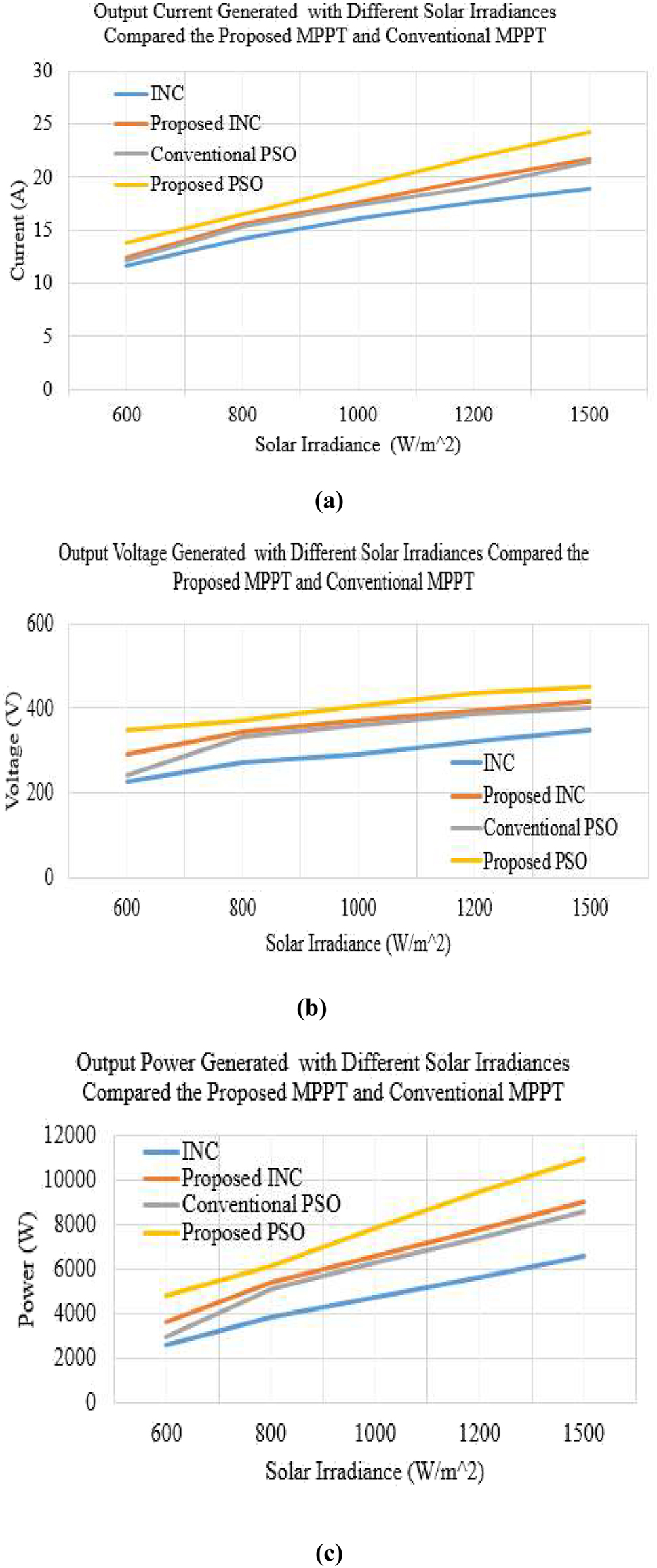
The proposed MPPT compared with the conventional MPPT. (a) Output current generated with different solar irradiance with a temperature of 25 °C. (b) Output voltage generated with different solar irradiance with a temperature of 25 °C. (c) Output power generated with different solar irradiance with a temperature of 25 °C.
From the results, the proposed improved incremental conductance and PSO produced an accurate result by generating more current, voltage, and power and also with fast tracking speed than the incremental conductance and conventional PSO which has already been proposed.
6 Experimental results and discussion
In Figure 13, an experiment was carried out to check the effectiveness of the proposed method. The PV array was connected to the computer. The proposed MPPT method was programmed by the computer using MATLAB Software. An oscilloscope was used to display the output generated power and the setup was connected with the DC-DC converter, DC-AC inverter, and a load. The DC-DC converter and DC-AC inverter circuit connections were done using the circuit board. The PV array was positioned in the direction of the sun for more sunlight to be received and also for the temperature of the surroundings to be captured. The output of the PV array was connected to the computer where the integration of the MATLAB Simulink code was interfaced with the dSpace 1104 controller and the proposed method was simulated. The output of the PV array was connected to the input of the DC-DC converter. The DC-DC converter circuit was connected with the capacitor in series to the inductor and diode. The output of the diode was connected in series to the capacitor and the capacitor was in parallel to the resistor. The output of the resistor was connected to the inverter circuit in series to the inductor, capacitor, and resistor, and then the output power generated is sent to the load. The experiment was carried out for 9 h between 8 am and 5 pm.
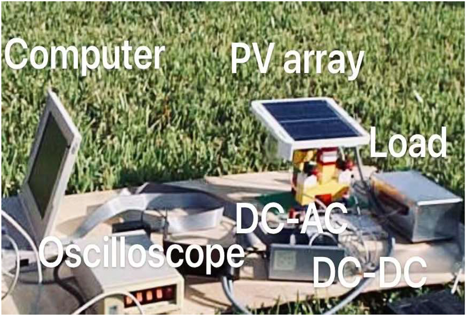
Experimental design setup.
Figure 14(a) and (b) show the solar irradiance and temperature received during the experiment time. The PV array received solar irradiance with an average between 400 W/m2 and 600 W/m2 and a temperature of 25 –30 °C during the experiment period. The highest solar irradiance received was 600 W/m2 at 2 pm since the sun was very hot with a temperature of 30 °C and the lowest solar irradiance received was 400 W/m2 at 5 pm with a temperature of 25 °C. At 5 pm, the sunlight started to decrease since the weather was approaching evening. The testing was carried out in the same experimental conditions with the proposed incremental conductance and particle swarm optimization method and then carried out with the conventional incremental conductance and particle swarm optimization method where the MATLAB Simulink code was interfaced with dSpace 1104 controller. The output power curve was displayed on an oscilloscope.
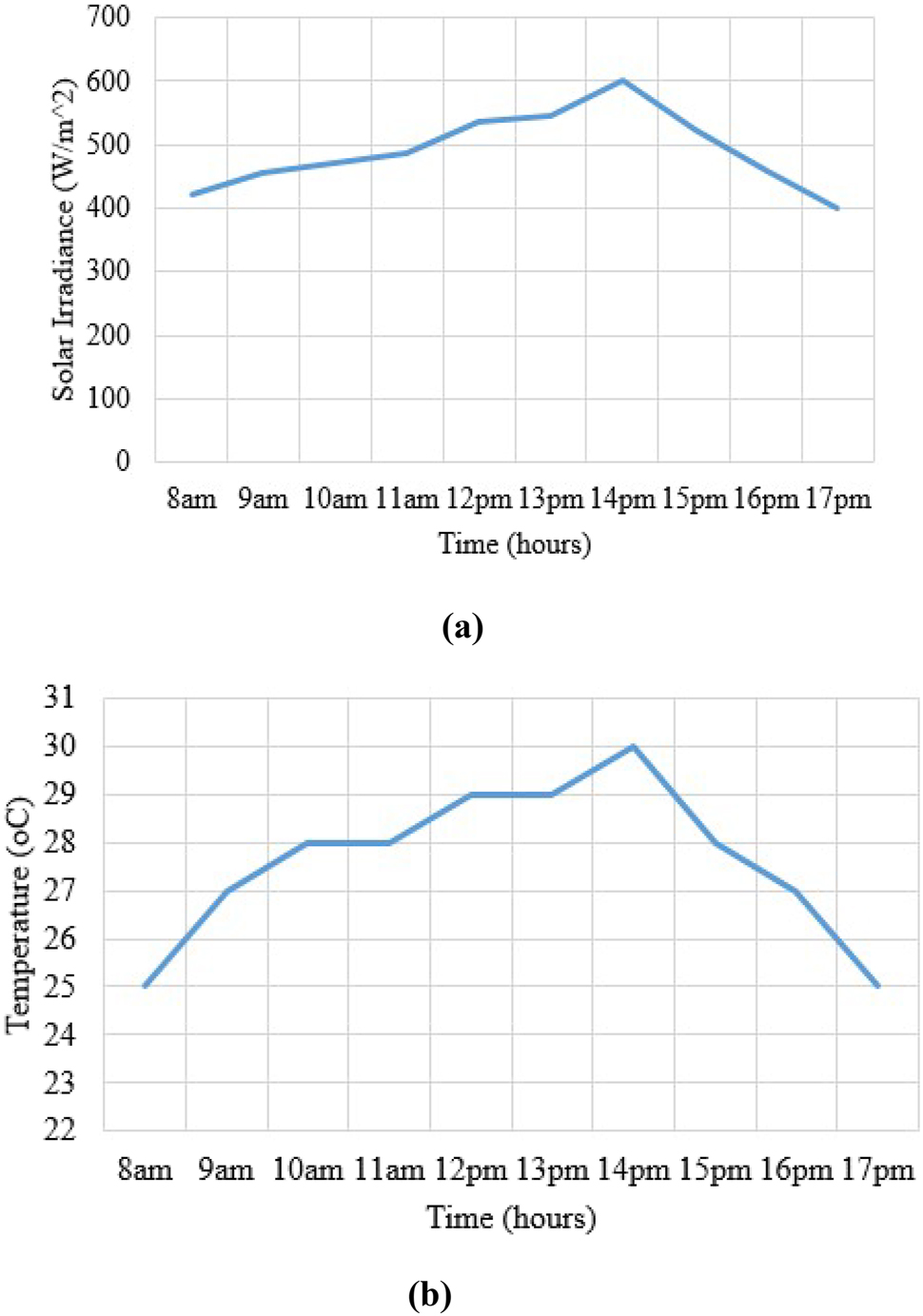
Recorded solar irradiance and temperature during experiment. (a) Solar irradiance with time. (b) Temperature with time.
Figure 15(a) and (b) show the output power generated by the proposed INC and PSO compared to the existing INC and PSO. From Figure 15(a), the proposed INC waveform shows that at 0.1 s, the power quickly changed and increased to 16.5 KW at 1s and then maintained its stability by changing quickly with the change in the environmental conditions and the conventional INC waveform shows that at the initial stage, it was able to change with the environmental condition from 0–1 s by attaining a power of 26 KW but at 1.1 s, it dropped to 22 KW and at 10 s, the power dropped from 22 KW at 1.1 s to 8 KW at 10 s which shows the instability of the conventional INC.
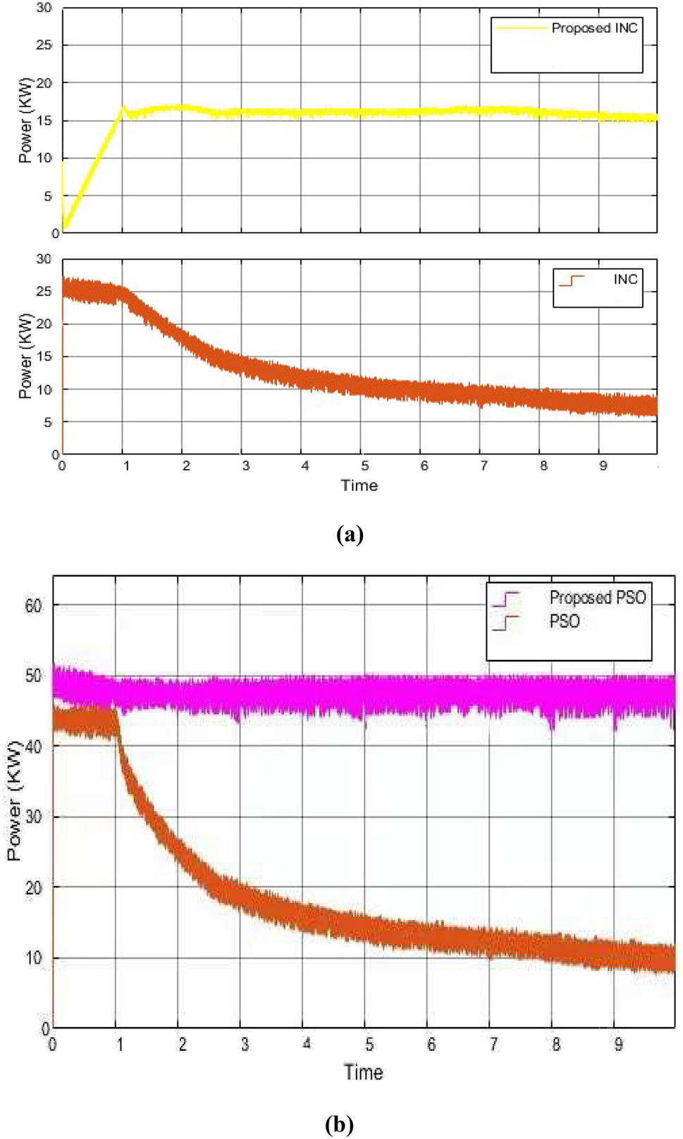
Experimental output power produced by the proposed MPPT methods compared with conventional MPPT methods. (a) Output power generated by the proposed INC compared with INC. (b) Output power generated by the proposed PSO compared with conventional PSO.
From Figure 15(b), the proposed PSO waveform shows that at 0.1 s, the power quickly changed and increased to 50 KW at 0.1 s and then maintained its stability by changing quickly with the change in the environmental conditions and the conventional PSO waveform shows that at the initial stage, it was able to change with the environmental condition at 0.1 s with a power of 45 KW but at 1.1 s, it dropped to 40 KW and at 10 s, the power dropped from 40 KW at 1.1 s to 10 KW at 10 s which shows the instability of the conventional PSO.
The proposed INC and PSO method generated more power and changed quickly with the change in solar irradiance and temperature without causing a decrease in the output power.
From Figure 16(a), the proposed INC tracking speed waveform shows that at the initial stage when the algorithm was connected, the change in environmental condition takes only 0.05 s for the proposed INC to change along which shows its high tracking speed by generating a power of 3 KW. At 0.1 s, the power increased to 36 KW to maintain its high tracking speed and stability. The tracking speed changes along with the environmental conditions which just takes only 0.05 s continuously. But the conventional INC dropped from 3 KW to 0 KW at 0.02 s because it couldn’t maintain its change with the change in the environmental condition at the initial stage. It then changed at 0.07 s and increased to 2.2 KW at 1 s.
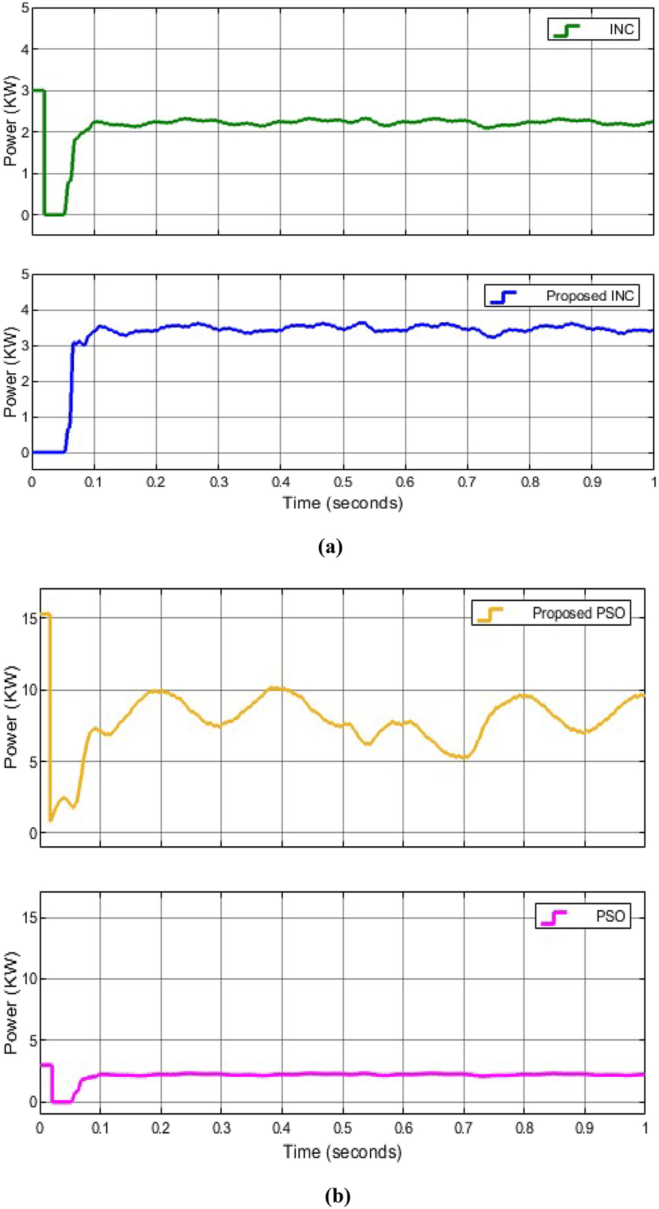
Experimental tracking speed by the proposed MPPT method compared with the conventional MPPT. (a) Output power generated tracking speed by the proposed INC compared with INC. (b) Output power generated tracking speed by the proposed PSO compared with conventional PSO.
From Figure 16(b), the proposed PSO tracking speed waveform shows that at the initial stage, the tracking speed at 0.01 s attained a power of 15 KW but then dropped to 1 KW and at 0.06 s, it increased to 8 KW and at 0.2 s, it increased to 10 KW. The change in the tracking speed was 0.03 s. The conventional PSO tracking speed waveform shows that at the initial stage, the tracking speed at 0.01 s attained a power of 3 KW and dropped to 0 KW and at 0.07 s, it increased to 2.5 KW. At 0.1 s, it maintained its stability with a tracking speed of 0.07 s.
Comparing Figure 16(a) and (b) show the output power generated with the tracking speed by the proposed INC and PSO compared with already existing INC and PSO. The tracking speed by the proposed method is very fast which generates more power and changed quickly with the change in solar irradiance by extracting more power from the PV array. When the solar irradiance is high, the tracking speed increases, and more power is extracted from the PV array faster. When the solar irradiance changes, the tracking speed changes along. When solar irradiance decreases, the output power decreases, and vice versa but when the temperature decreases, the output power increases. High temperature decreases the output voltage of the PV array.
From the experimental results, when there is a change in solar irradiance, the output of the PV array changes along with a fast-changing observed changing time is 0.1 s which shows the fastness of the proposed algorithm.
7 Conclusion
A control structure is designed to produce power using an improved incremental conductance and particle swarm optimization method to be the maximum power point tracker. The proposed PSO has been improved whereby maximum power is tracked quickly from the PV array under fast-changing solar irradiance and temperature without any tracking failure or delay. The proposed INC method has been improved by using signals to track maximum power from the PV array using high convergence speed. The system was then connected to DC to DC converter and DC to AC inverter. A simulation was carried out in MATLAB Simulink with different solar irradiance and temperature whereby the conventional INC and PSO were compared with the proposed INC and PSO. An experiment was carried out for a whole day from 8 am to 5 pm to test the validity of the proposed algorithm and compared it with the conventional INC and PSO. From both the simulation and experimental results, the proposed INC and PSO performed better by attaining high power and tracking speed with stable output results than the conventional INC and PSO.
-
Author contribution: Amoh Mensah Akwasi: Conceptualization, Methodology, Writing-Original Draft Preparation. Xie Wei: Supervision, Writing-Reviewing and Editing. Otuo-Acheampong Duku: Software, Validation, Data curation. Tumbiko Mbuzi: Visualization, Investigation.
-
Research funding: None declared.
-
Conflict of interest statement: The authors declare no conflict of interest for this research.
References
Access, C. G., Castano, C. Restrepo, S. Kouro, and J. Rodriguez. 2021. “MPPT Algorithm Based on Artificial Bee Colony for PV System.” IEEE 9: 43121–33. https://doi.org/10.1109/ACCESS.2021.3066281.Search in Google Scholar
Ahmed, J., and Z. Salam. 2018. “An Enhanced Adaptive P&O; ’MPPT for Fast and Efficient Tracking under Varying Environmental Conditions.” IEEE Transactions on Sustainable Energy 9 (3): 1487–96. https://doi.org/10.1109/TSTE.2018.2791968.Search in Google Scholar
Akwasi, A. M., H. Chen, O. A. Duku, and T. Mbuzi. 2022. “Solar Power Generation System Based on Signal Search Artificial Bee Colony Optimization Algorithm for Maximum Power Point Tracking.” In 2022 the 12th International Conference on Power and Energy Systems (ICPES 2022), 914–8. Guangzhou: IEEE.Search in Google Scholar
Akwasi, A. M., and W. Xie. 2022. “Design of Control System for Solar Power Generation Based on an Improved Bat Algorithm for an Island Operation.” Energy Harvesting and System. https://doi.org/10.1515/ehs-2022-0045.Search in Google Scholar
Bhos, C. D., J. Sayyad, and P. Nasikkar. 2022. “Power Enhancement Using Improved Maximum Power Point Tracking for Solar Photovoltaic Systems under Partial Shading.” Clean Energy 6 (No. 6): 810–6. https://doi.org/10.1093/ce/zkac062.Search in Google Scholar
Devana, S., G. Gengi, K. V. Bindu, R. S. Anand, S. Ananthakrishnan, and J. Kishorekumar. 2022. “Improved Perturb & Observation Maximum Power Point Tracking Techniques for Solar Photovoltaic Power Generation Systems.” Journal of Health Science 6 (4): 4945–54.10.53730/ijhs.v6nS4.9207Search in Google Scholar
Duku, O. A., I. R. Ghamgeen, H. Hussain, and A. M. Akwasi. 2022. “Using Artificial Bee Colony Algorithm for STATCOM Sizing and Placement to Prevent Voltage Instability on Pakistan Power System.” In 2022 7th Asia Conference on Power and Electrical Engineering (ACPEE 2022), 2129–34. Hangzhou: IEEE.10.1109/ACPEE53904.2022.9784011Search in Google Scholar
Eltamaly, A. M., H. M. Farh, and M. S. Al-Saud. 2019. “Grade Point Average Assessment for Metaheuristic GMPP Techniques of Partial Shaded PV Systems.” IET Renewable Power Generation 13 (8): 1215–31. https://doi.org/10.1049/iet-rpg.2018.5336.Search in Google Scholar
Eltamaly, A. M., M. S. Al-Saud, A. G. Abokhalil, and H. M. H. Farh. 2020. “Photovoltaic Maximum Power Point Tracking under Dynamic Partial Shading Changes by Novel Adaptive Particle Swarm Optimization Strategy.” Transactions of the Institute of Measurement and Control 42 (1): 104–15. https://doi.org/10.1177/0142331219865627.Search in Google Scholar
Farh, H. M., and M. Ali Eltamaly. 2020. Maximum Power Extraction from the Photovoltaic System under Partial Shading Conditions in Modern Maximum Power Point Tracking Techniques for Photovoltaic Energy Systems, 107–29. Cham: Springer.10.1007/978-3-030-05578-3_4Search in Google Scholar
Ghasemi, M. A., H. M. Forushanis, and M. Parniani. 2016. “Partial Shading Detection and Smooth Maximum Power Point Tracking of PV Arrays under PSC.” IEEE Transactions on Industrial Electronics 31 (9): 6281–92. https://doi.org/10.1109/TPEL.2015.2504515.Search in Google Scholar
Hernanz, J. R., I. Uriarte, J. M. L. Guede, U. F. Gamiz, A. Mesanza, and E. Zulueta. 2020. “Temperature Based Maximum Power Point Tracking for Photovoltaic Modules.” Scientific Reports 10: 12476. https://doi.org/10.1038/s41598-020-69365-5.Search in Google Scholar PubMed PubMed Central
Hong, Y. Y., P. M. P. Buay, and A. A. Beltran. 2019. “Maximum Power Point Tracking of Photovoltaic System Using Taguchi-Based Fuzzy Logic Control.” In Proc. IEEE Milan Power Tech, 1–6. Milan.10.1109/PTC.2019.8810887Search in Google Scholar
Ilyas, A., M. Ayyub, M. R. Khans, A. Jain, and M. A. Husain. 2018. “Realization of Incremental Conductance the MPPT Algorithm for a Solar Photovoltaic System.” International Journal of Ambient Energy 39 (8): 873–84. https://doi.org/10.1080/01430750.2017.1354322.Search in Google Scholar
Kumar, N., B. Singh, and B. K. Panigrahi. 2022. “Voltage Sensorless Based Model Predictive Control with Battery Management System: For Solar PV Powered On-Board EV Charging.” IEEE Transactions on Transportation Electrification. https://doi.org/10.1109/TTE.2022.3213253.Search in Google Scholar
Kumari, P., N. Kumar, and B. K. Panigrahi. 2022. “A Framework of Reduced Sensor Rooftop SPV System Using Parabolic Curve Fitting MPPT Technology for Household Consumers.” IEEE Transactions on Consumer Electronics. https://doi.org/10.1109/TCE.2022.3209974.Search in Google Scholar
Kumar, N., and S. K. Panda. 2022. “A Multipurpose and Power Quality Improved Electric Vessels Charging Station for the Seaports.” IEEE Transactions on Industrial Informatics. https://doi.org/10.1109/TII.2022.3170424.Search in Google Scholar
Kumar, N., and S. K. Panda. 2022. “Smart High Power Charging Networks and Optimal Control Mechanism for Electric Ships.” IEEE Transactions on Industrial Informatics. https://doi.org/10.1109/TII.2022.3170484.Search in Google Scholar
Loukriz, A., M. Haddadi, and S. Messalti. 2016. “Simulation and Experimental Design of a New Advanced Variable Step Size Incremental Conductance MPPT Algorithm for PV Systems.” ISA Transactions 62: 30–8. https://doi.org/10.1016/j.isatra.2015.08.006.Search in Google Scholar PubMed
Liao, C. Y., R. K. Subroto, I. S. Millah, K. L. Lian, and W. T. Huang. 2020. “An Improved Bat Algorithm for More Efficient and Faster Maximum Power Point Tracking for a Photovoltaic System under Partial Shading Conditions.” IEEE Access 8: 96378–90. https://doi.org/10.1109/ACCESS.2020.2993361.Search in Google Scholar
Li, H., D. Yang, W. Su, J. Lu, and X. Yu. 2019. “An Overall Distribution Particle Swarm Optimization MPPT Algorithm for Photovoltaic System under Partial Shading.” IEEE Transactions on Industrial Electronics 66 (1): 265–75. https://doi.org/10.1109/TIE.2018.2829668.Search in Google Scholar
Manickam, C. R., G. R. Raman, and G. P. Ganesan, S. I. C. Nagamani. 2016. “A Hybrid Algorithm for Tracking of GMPP Based on P&O and PSO with Reduced Power Oscillation in String Inverters.” IEEE Transactions on Industrial Electronics 63 (10): 6097–106. https://doi.org/10.1109/TIE.2016.2590382.Search in Google Scholar
Manoharan, P., U. Subramaniam, T. S. Babu, S. Padmanaban, J. B. M. Holm-NielsenMitolo, and S. Ravichandran. 2021. “Improved Perturb and Observation Maximum Power Point Tracking Technique for Solar Photovoltaic Power Generation Systems.” IEEE Systems Journal 15 (2): 3024–35. https://doi.org/10.1109/JSYST.2020.3003255.Search in Google Scholar
Mao, M., Q. Duan, Z. Yang, and P. Duan. 2016. “Modeling and Global MPPT for PV System under Partial Shading Conditions Using Modified Artificial Fish Swarm Algorithm.” In IEEE International Symposium on Systems Engineering (ISSE), 1–7.10.1109/SysEng.2016.7753188Search in Google Scholar
Motahhir, S., A. Chalh, A. Ghzizal, S. Sebti, and A. Derouich. 2017. “Modeling of the Photovoltaic Panel by Using Proteus.” Journal of Engineering Science and Technology Review 10 (2): 8–13. https://doi.org/10.25103/jestr.102.02.Search in Google Scholar
Mishra, P. K., and P. Tiwari. 2021. “Incremental Conductance MPPT in Grid Connected PV System.” International Journal of Engineering, Science and Technology 13 (1): 138–45. https://doi.org/10.4314/ijest.v13i1.21S.Search in Google Scholar
Motahhir, S., A. El Ghzizal, S. Sebti, and A. Derouich. 2018. “Modeling of Photovoltaic System with Modified Incremental Conductance Algorithm for Fast Changes of Irradiance.” International Journal of Photoenergy. https://doi.org/10.1155/2018/3286479.Search in Google Scholar
Premkumar, M., and R. Sowmya. 2019. “An Effective Maximum Power Point Tracker for Partially Shaded Solar Photovoltaic Systems.” Energy Reports 5: 1445–62. https://doi.org/10.1016/j.egyr.2019.10.006.Search in Google Scholar
Pilakkat, D., and S. Kanthalakshm. 2019. “An Improved P&O Algorithm Integrated with Artificial Bee Colony for Photovoltaic Systems under Partial Shading Conditions.” Solar Energy 178: 37–47. https://doi.org/10.1016/j.solener.2018.12.008.Search in Google Scholar
Premkumar, M., C. Kumar, A. Anbarasan, and R. Sowmya. 2022. “A New Maximum Power Point Tracking Technique Based on Whale Optimisation Algorithm for Solar Photovoltaic Systems.” International Journal of Ambient Energy 43 (1): 5627–37. https://doi.org/10.1080/01430750.2021.1969270.Search in Google Scholar
Premkumar, M., A. Mohamed Ibrahim, R. Mohan Kumar, and R. Sowmya. 2019. “Analysis and Simulation of Bio-Inspired Intelligent Salp Swarm MPPT Method for the PV Systems under Partial Shaded Conditions.” International Journal of Computing and Digital Systems 8 (5): 489–96. https://doi.org/10.12785/ijcds/080506.Search in Google Scholar
Premkumar, M., C. Kumar, R. Sowmya, and J. Pradeep. 2021. “A Novel Salp Swarm Assisted Hybrid Maximum Power Point Tracking Algorithm for the Solar Photovoltaic Power Generation Systems.” Automatika 62 (1): 1–20. https://doi.org/10.1080/00051144.2020.1834062.Search in Google Scholar
Premkumar, M., and R. Sumithira. 2018. “Humpback Whale Assisted Hybrid Maximum Power Point Tracking Algorithm for Partially Shaded Solar Photovoltaic Systems.” Journal of Power Electronics 18 (6): 1805–18. https://doi.org/10.6113/JPE.2018.18.6.1805.Search in Google Scholar
Priyadarshi, N., S. Padmanaban, P. K. Maroti, and A. Sharma. 2019. “An Extensive Practical Investigation of FPSO-Based MPPT for Grid Integrated PV System under Variable Operating Conditions with Anti-islanding Protection.” IEEE Systems Journal 13 (2): 1861–71. https://doi.org/10.1109/JSYST.2018.2817584.Search in Google Scholar
Renaudineau, H., F. Donatantonio, J. Fontchastagner, G. Petrone, G. Spagnuolo, J. P. Martin, and S. Pierfederici. 2015. “A PSO-Based Global MPPT Technique for Distributed PV Power Generation.” IEEE Transactions on Industrial Electronics 62 (2): 1047–58. https://doi.org/10.1109/TIE.2014.2336600.Search in Google Scholar
Sridhar, R. J., S. Dash, and P. Vishnuram. 2017. “A New Maximum Power Tracking in PV System during Partially Shaded Conditions Based on Shuffled Frog Leap Algorithm.” Journal of Experimental and Theoretical Artificial Intelligence 29 (3): 481–93. https://doi.org/10.1080/0952813X.2016.1186750.Search in Google Scholar
Saha, J., N. Kumar, and S. K. Panda. 2022. “A Futuristic Silicon-Carbide (SiC) Based Electric Vehicle Fast Charging/Discharging (FC/dC) Station.” IEEE Journal of Emerging and Selected Topics in Power Electronics. https://doi.org/10.1109/JESTPE.2022.3223417.Search in Google Scholar
Siu, J. Y., N. Kumar, and S. K. Panda. 2022. “Command Authentication Using Multi Agent System for Attacks on the Economic Dispatch Problem.” IEEE Transactions on Industry Applications 58 (4): 4381–93. https://doi.org/10.1109/TIA.2022.3172240.Search in Google Scholar
Ujgare, V. W., M. D. Goudar, and R. D. Kharadkar. 2022. “Optimized Maximum Power Point Tracker for Partially Shaded PV System: Adaptive Duty Cycle Control.” International Journal of Intelligent Robotics and Applications. https://doi.org/10.1007/s41315-022-00249-9.Search in Google Scholar
Yetayew, T. T., T. R. Jyothsna, and G. Kusuma. 2016. “Evaluation of Incremental Conductance and Firefly Algorithm for PV MPPT Application under Partial Shading Condition.” In Proc. Int. Conf. Power Syst., 1–6.10.1109/ICPES.2016.7584089Search in Google Scholar
Zhu, W., L. Shang, P. Li, H. Guo. 2018. ‘‘Modified Hill Climbing MPPT Algorithm with Reduced Steady-State Oscillation and Improved Tracking Efficiency.” Engage 2018 (17): 1878–83. https://doi.org/10.1049/joe.2018.8337.Search in Google Scholar
© 2024 the author(s), published by De Gruyter, Berlin/Boston
This work is licensed under the Creative Commons Attribution 4.0 International License.
Articles in the same Issue
- Solar photovoltaic-integrated energy storage system with a power electronic interface for operating a brushless DC drive-coupled agricultural load
- Analysis of 1-year energy data of a 5 kW and a 122 kW rooftop photovoltaic installation in Dhaka
- Reviews
- Real yields and PVSYST simulations: comparative analysis based on four photovoltaic installations at Ibn Tofail University
- A comprehensive approach of evolving electric vehicles (EVs) to attribute “green self-generation” – a review
- Exploring the piezoelectric porous polymers for energy harvesting: a review
- A strategic review: the role of commercially available tools for planning, modelling, optimization, and performance measurement of photovoltaic systems
- Comparative assessment of high gain boost converters for renewable energy sources and electrical vehicle applications
- A review of green hydrogen production based on solar energy; techniques and methods
- A review of green hydrogen production by renewable resources
- A review of hydrogen production from bio-energy, technologies and assessments
- A systematic review of recent developments in IoT-based demand side management for PV power generation
- Research Articles
- Hybrid optimization strategy for water cooling system: enhancement of photovoltaic panels performance
- Solar energy harvesting-based built-in backpack charger
- A power source for E-devices based on green energy
- Theoretical and experimental investigation of electricity generation through footstep tiles
- Experimental investigations on heat transfer enhancement in a double pipe heat exchanger using hybrid nanofluids
- Comparative energy and exergy analysis of a CPV/T system based on linear Fresnel reflectors
- Investigating the effect of green composite back sheet materials on solar panel output voltage harvesting for better sustainable energy performance
- Electrical and thermal modeling of battery cell grouping for analyzing battery pack efficiency and temperature
- Intelligent techno-economical optimization with demand side management in microgrid using improved sandpiper optimization algorithm
- Investigation of KAPTON–PDMS triboelectric nanogenerator considering the edge-effect capacitor
- Design of a novel hybrid soft computing model for passive components selection in multiple load Zeta converter topologies of solar PV energy system
- A novel mechatronic absorber of vibration energy in the chimney
- An IoT-based intelligent smart energy monitoring system for solar PV power generation
- Large-scale green hydrogen production using alkaline water electrolysis based on seasonal solar radiation
- Evaluation of performances in DI Diesel engine with different split injection timings
- Optimized power flow management based on Harris Hawks optimization for an islanded DC microgrid
- Experimental investigation of heat transfer characteristics for a shell and tube heat exchanger
- Fuzzy induced controller for optimal power quality improvement with PVA connected UPQC
- Impact of using a predictive neural network of multi-term zenith angle function on energy management of solar-harvesting sensor nodes
- An analytical study of wireless power transmission system with metamaterials
- Hydrogen energy horizon: balancing opportunities and challenges
- Development of renewable energy-based power system for the irrigation support: case studies
- Maximum power point tracking techniques using improved incremental conductance and particle swarm optimizer for solar power generation systems
- Experimental and numerical study on energy harvesting performance thermoelectric generator applied to a screw compressor
- Study on the effectiveness of a solar cell with a holographic concentrator
- Non-transient optimum design of nonlinear electromagnetic vibration-based energy harvester using homotopy perturbation method
- Industrial gas turbine performance prediction and improvement – a case study
- An electric-field high energy harvester from medium or high voltage power line with parallel line
- FPGA based telecommand system for balloon-borne scientific payloads
- Improved design of advanced controller for a step up converter used in photovoltaic system
- Techno-economic assessment of battery storage with photovoltaics for maximum self-consumption
- Analysis of 1-year energy data of a 5 kW and a 122 kW rooftop photovoltaic installation in Dhaka
- Shading impact on the electricity generated by a photovoltaic installation using “Solar Shadow-Mask”
- Investigations on the performance of bottle blade overshot water wheel in very low head resources for pico hydropower
- Solar photovoltaic-integrated energy storage system with a power electronic interface for operating a brushless DC drive-coupled agricultural load
- Numerical investigation of smart material-based structures for vibration energy-harvesting applications
- A system-level study of indoor light energy harvesting integrating commercially available power management circuitry
- Enhancing the wireless power transfer system performance and output voltage of electric scooters
- Harvesting energy from a soldier's gait using the piezoelectric effect
- Study of technical means for heat generation, its application, flow control, and conversion of other types of energy into thermal energy
- Theoretical analysis of piezoceramic ultrasonic energy harvester applicable in biomedical implanted devices
- Corrigendum
- Corrigendum to: A numerical investigation of optimum angles for solar energy receivers in the eastern part of Algeria
- Special Issue: Recent Trends in Renewable Energy Conversion and Storage Materials for Hybrid Transportation Systems
- Typical fault prediction method for wind turbines based on an improved stacked autoencoder network
- Power data integrity verification method based on chameleon authentication tree algorithm and missing tendency value
- Fault diagnosis of automobile drive based on a novel deep neural network
- Research on the development and intelligent application of power environmental protection platform based on big data
- Diffusion induced thermal effect and stress in layered Li(Ni0.6Mn0.2Co0.2)O2 cathode materials for button lithium-ion battery electrode plates
- Improving power plant technology to increase energy efficiency of autonomous consumers using geothermal sources
- Energy-saving analysis of desalination equipment based on a machine-learning sequence modeling