Effect of in situ graphene-doped nano-CeO2 on microstructure and electrical contact properties of Cu30Cr10W contacts
-
Shengli Liang
 ,
Meng Zhou
,
Baohong Tian
,
Meng Zhou
,
Baohong Tian

Abstract
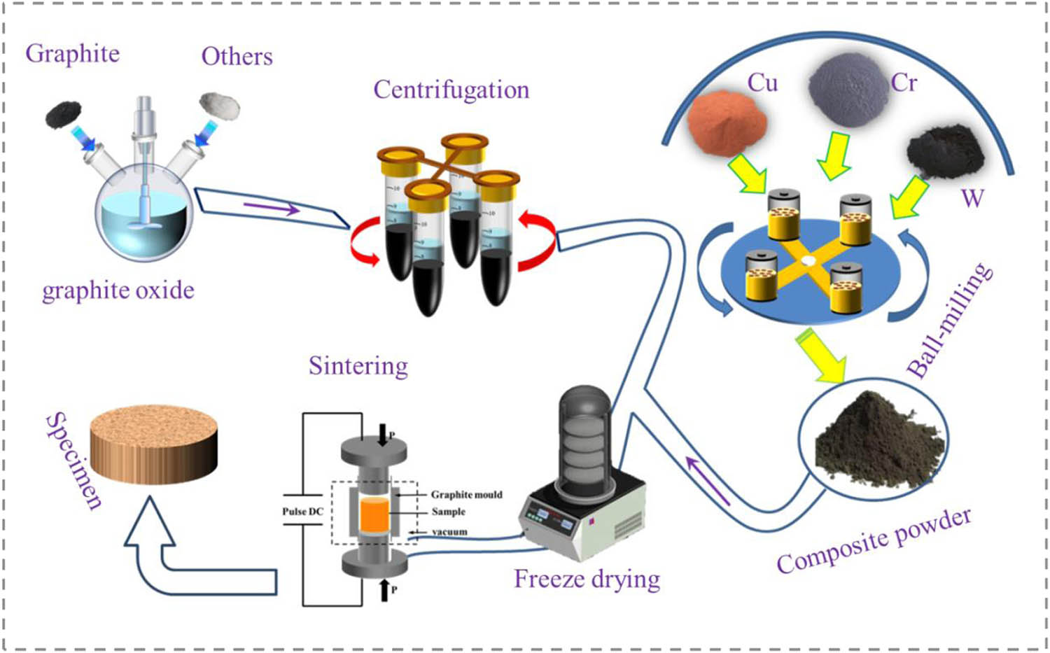
The graphene oxide (GO)-doped nano-CeO2 was introduced into Cu30Cr10W electrical contact composites by ball milling dispersion, freeze-drying, and spark plasma sintering, resulting in excellent mechanical strength and high arc erosion resistance. The effects of GO and CeO2 on the microstructure and properties of the composites were investigated. The arc erosion behavior was investigated by the JF04C electrical contact testing apparatus. Consequently, the uniform distribution of CeO2 nanoparticles hinders the movement of dislocations, GO transformed into reduced graphene oxide (rGO) during high-temperature sintering, and the in situ formation of Cr3C2 between trace carbon atoms and chromium particles at the C–Cu interface, which enhanced the interface combination. Compared with Cu30Cr10W composites, the tensile strength of the two composites was increased by 47 and 36% by importing GO and nano-CeO2, respectively. Finally, electrode material migrated from the cathode to the anode, and the rGO delayed the formation of pits and sharp bumps on the contact surface of the electrode and inhibited diffusion of molten metal; when compared with Cu30Cr10W, the GO/CeO2–Cu30Cr10W composites have better welding force.
Graphical abstract
1 Introduction
Owing to its high electrical and thermal conductivity, along with remarkable processing performance, copper is widely used in the aerospace, electronics industries, and power transmission, including high-speed rail contact wires and electrical contact materials [1]. Electric contact is the bridge between electrical and electronic components and power transmission, playing a vital role in electrical circuits [2,3]. At present, all kinds of equipment are developing toward miniaturization and lightweight, which requires the comprehensive properties of copper matrix composites to improve vastly [4,5,6]. Recently, copper matrix composites with two or more reinforcing phases have been deeply studied, which have better properties than copper matrix composites with single reinforcing phase [7]. Through the combination of matrix and reinforcing phase, the excellent properties of different materials are superimposed to realize the complementary properties among the materials [8,9]. For the time being, the commonly utilized reinforcing phases are Al2O3 [10], SiC [11], AlN [12], and TiB2 [13]. Lee et al. [14] prepared nanometer Al2O3 dispersed copper matrix composites by the internal oxidization-hot extrusion process and explained the strengthening mechanism with the Orowan reinforcement theory. However, the increase in strength can destroy the conductivity [15]. Therefore, the strategy of using graphene as reinforcement arises at the historic moment, the introduction of graphene into copper matrix composites is rare, and there must be matching advanced preparation technology. The schematic representation of the process is shown in graphical abstract.
Graphene, known as “the wonder material of today’s scientific world,” is not only the strongest material to be discovered to date but also is the thinnest material [16]. In recent years, graphene and its derivatives have drawn attention due to their excellent mechanical and electrical properties [17,18]. It is two-dimensional honeycomb hexagonal lattice structure composed of a single layer of carbon atoms tightly packed through sp2 hybridized orbitals, which can be coated to form fullerenes and carbon nanotubes [19,20]. It has ultra-high breaking strength (130 GPa) [21], excellent Young’s modulus (1 TPa) [22], high carrier mobility (15,000 cm2 V−1 s−1) [23], high thermal conductivity (5,000 W m−1 K−1) [24], and large specific surface area (2,630 m2 g−1) [25]; its application prospect in various fields, such as energy storage, radiator, sensors, aviation and space, and anti-bacterial [26]. However, most of these features cannot be achieved in practice. Theoretically modeled physicochemical parameters of graphene plane are modified by impurities, defects, admixtures, presence of substrate, and connection of several layers or chemical functionalization [27].
At present, the majority of the research on electric contact materials focuses on copper composite materials, which can be prepared by chemical vapor deposition, mechanical alloying, in situ synthesis, and powder metallurgy. Compared with traditional copper alloys and silver-based electric contact materials, the comprehensive performance was significantly improved [28,29]. Li et al. [4] adopted chemical vapor deposition (CVD), and severe plastic deformation graphene was prepared in situ reinforced copper matrix composites. The uniformly distributed graphene pinned dislocations and provided a high-speed channel for the movement of electrons; the material tensile strength and electric conductivity reached 595 MPa and 5.46 × 10⁷ S/m, respectively.
Under laboratory conditions, the research of graphene and its derivatives reinforced copper matrix composites has achieved remarkable results, but they are still not ready for industrial production. To date, the problems of homogenous dispersion, agglomeration, and interfacial bonding have still not been explored comprehensively [30,31]. The van der Waals forces result in the agglomeration of graphene in the process of dispersion, which results in the limited strengthening effect on the metal matrix or even the negative toughening effect [32,33].
In order to solve this problem, graphene derivatives have been extensively investigated. GO contains a large number of hydrophilic functional groups, which improves GO wettability, dispersibility, and surface activity [34] as well as significantly improves the binding of graphene to the matrix. However, the existence of a large number of functional groups greatly reduces the excellent properties of graphene, such as electrical conductivity and mechanical properties [35]. Wang et al. [36] found that GO lost some functional groups and converted to rGO during discharge plasma sintering, which improved the conductivity. Using the combination of preloading and CVD, Chen et al. [37] prepared excellent three-dimensional (3D) interlinked CNTs/Cu composites, which provided a new and effective way for the preparation of high performance copper matrix composites.
Another key issue is how to enhance interface cohesion. Nonetheless, graphene itself has a weak affinity with copper matrix, which is the bottleneck restricting the development of graphene copper matrix composites. The results show that under certain conditions, the in situ formation of strong carbides can effectively improve the interface bonding. Zhang et al. [38] prepared GO/Al2O3-Cu35W5Cr copper matrix composites by vacuum hot-pressing sintering method. The larger thermal expansion coefficient difference between graphene and copper leads to high-density dislocations at the grain boundaries, and the Cr3C2 generated in situ can significantly improve the interfacial bond strength. However, in the research process of graphene-doped rare earth oxide synergistic strengthening of copper matrix composites, there were few reports of electrical contacts. In the research of contact materials, Shao et al. [39] prepared multi-layer GNPs/Cu composites by electrostatic self-assembly and electroless copper plating. The GNPS coating effectively inhibits the splash of liquid metal, and the arc erosion resistance of the materials was significantly improved.
At present, rare earth oxide with high ionic conductivity has become a potential reinforcing phase of copper matrix composites, which has little harm to the conductivity while improving the material strength [40,41,42]. At present work, GO and CeO2 particles were introduced into copper matrix, the GO/CeO2–Cu30Cr10W electrical contact material was successfully prepared by spark plasma sintering (SPS). X-ray diffraction (XRD) and Raman spectroscopy were used to analyze the powder materials. The structural changes of graphene oxide were investigated by X-ray photoelectron spectroscopy (XPS). The microstructure of the materials was analyzed by scanning electron microscopy (SEM), transmission electron microscopy (TEM), and high-resolution electron microscopy (HRTEM). Finally, the electrical contact properties of the composites were studied by using the JF04C contact test system.
2 Experiments
2.1 Materials
Pure copper powder (purity ≥99.95%, average particle size: 5–10 μm) was provided by Nangong Xiangfan Alloy Material Co., Ltd; tungsten powder and chromium powder (purity ≥99.95%, average particle size: 5 and 47 μm) were purchased from Beijing Xing Rong Yuan Technology Co., Ltd; natural graphite (purity ≥99.5%, 300 mesh) was purchased from Tianjin Fengfan Technology Co., Ltd.; cerium oxide (AR, purity ≥99.95%, particle size <50 nm) was provided by Shanghai Aladdin Biochemical Technology Co., Ltd.
2.2 Preparation of composite materials
An appropriate amount of anhydrous ethanol was added into the mixed metal powder and ball-milled in the QM-3SP2 planetary ball mill at 350 rpm for 4 h and then removed. Pure copper balls were used as a grinding medium (ball to material ratio was 5:1) to prevent particles from uniting. GO was prepared by the modified Hummers’ method [43], and then GO and nano-CeO2 were dispersed in 500 mL deionized water for 1.5 h to prepare a suspension. The ball-milled powder was transferred to suspension and mechanically stirred for 6 h. The obtained turbid liquid was placed into the LGJ-12 freeze dryer with a vacuum degree of 6 × 10⁻² Pa and a cold trap temperature of −60°C. After 72 h, the sample was transferred to the YH-10 mixer (the ratio of the ball to the material was 10:1) and mixed in an atmospheric environment at the speed of 50 rpm for 4 h to obtain a composite powder.
The composite powders were transferred into the high strength graphite mold, and the sintering of the composite was carried out in the SPS-20T-10 SPS furnace (vacuum degree 6 × 10⁻² Pa, heating rate 100°C/min). After sintering, the samples were cooled to below 100°C in the furnace and removed to obtain the ∅ 50 mm × 20 mm samples.
2.3 Microstructure and properties characterization
The morphology of the powders and the microstructure of the sintered samples were observed by SEM, TEM, and HRTEM. Powders were characterized by XRD and Raman spectra. X-ray photoelectron spectroscopy (XPS) was used to make a thorough inquiry into the state changes of carbon atoms in GO before and after sintering. Sigma 2008B1 conductivity meter measures the conductivity of the sintered samples. Nine areas were selected on the surface of the sintered sample, and the hardness was measured using the HV-100 Vickers hardness tester under 200 g load. The relative density of sintered samples was measured and calculated by the Archimedes method with deionized water at 21°C. Tensile tests were performed using Shimadzu AG-I 250 kN universal testing machine at room temperature.
2.4 Electrical contact tests
After sintering, the composite material was processed into electrical contact with a smooth end face and ∅ 3.8 × 8 mm size. Under DC load, 5,000 test cycles were completed on the JF04C contact test device. The action contact was used as the anode and the static contact as the cathode. The test voltage was set at 25 V, the current was 10, 20, 25, and 30 A, and the contact force was between 40 and 60 cN. Before and after the electrical contact test, the samples were weighed five times, and the average value was calculated to calculate the mass change of the two electrodes. As shown in Formula (1):
3 Results
3.1 Morphology of GO and composite powder
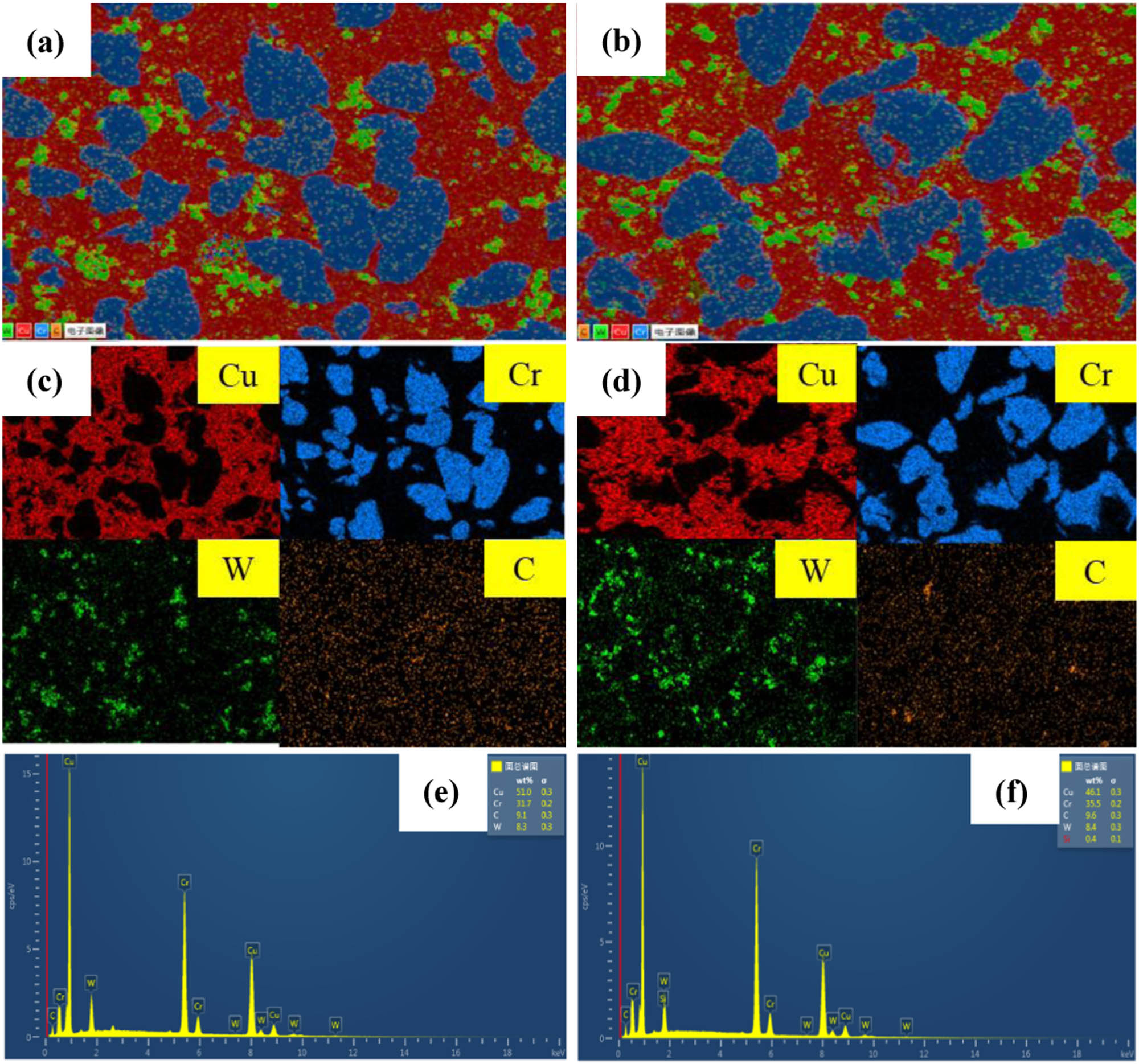
TEM can show the edge wrinkle morphology of graphene oxide, and the number of layers of GO can be measured at the edge of the multilayer region [44,45]. Figure 1(a and b) is a TEM image of graphene oxide after ultrasonic dispersion by vacuum freeze-drying transferred to microgrid copper mesh. The edge of GO presents convolution like folds and several Fresnel stripes can be seen on the edge, which can indicate the number of layers of graphene oxide. Figure 1(c–f) shows that part of the powders have been alloyed, and the presence of GO flakes is observed in both composite powders. Meanwhile, the original structure of GO was not destroyed after freeze-drying and ball milling. According to the energy dispersion spectra (EDS) in Figure 1(g) and (h), the surface of GO sheets after ball milling and freeze-drying contains cerium oxide and copper, chromium, and tungsten metal particles.
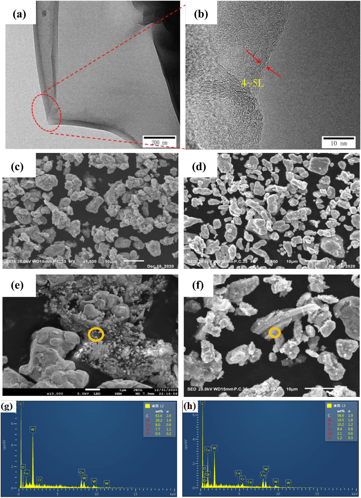
Morphology of GO and composites powder: (a and b) TEM of GO flakes; (c, e, and g) SEM morphology and EDS results of 0.5GO/0.5CeO2–Cu30Cr10W; (d, f, and h) SEM morphology and EDS resultsof 1.0GO/0.5CeO2–Cu30Cr10W.
3.2 XRD, Raman spectroscopy, and XPS analysis
Figure 2(a) shows the XRD patterns of graphite and GO. It can be seen from the figure that the 2θ peak of graphite is 26.5° and the 2θ peak shifts to 10.5° due to the strong oxidation, which corresponds to the characteristic diffraction peaks of natural graphite (PDF#75-2078) and GO [36]. Layer spacing can be calculated from the Bragg’s law equation:
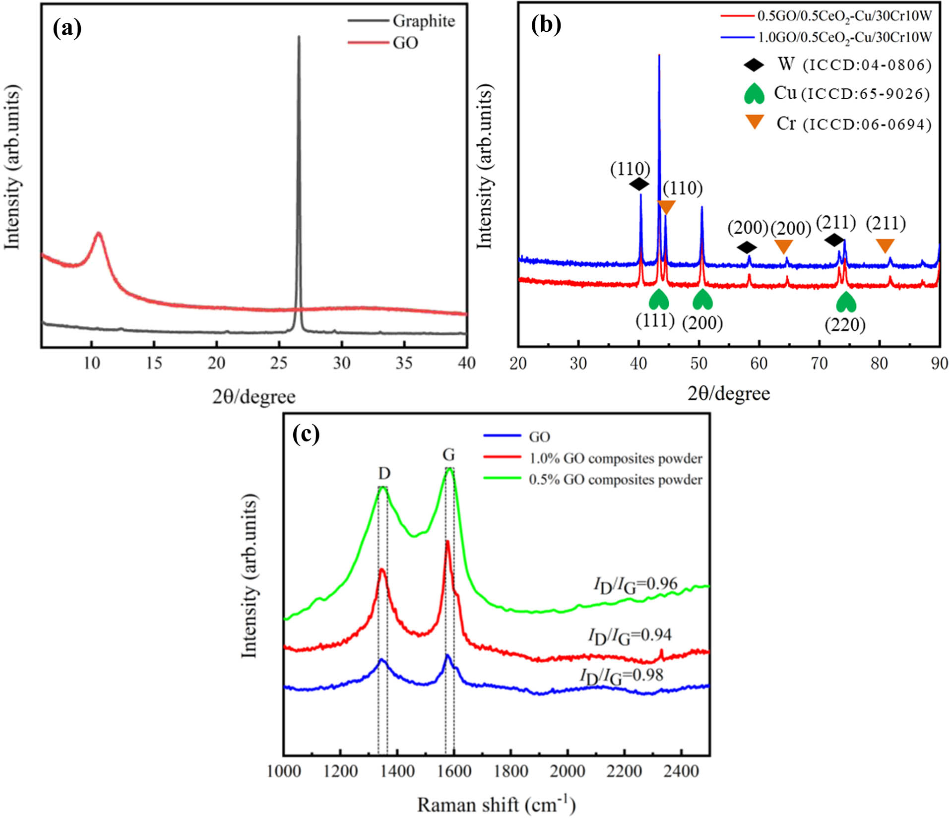
(a) XRD patterns of GO and graphite and (b and c) XRD and Raman patterns of the composites powder.
Here, d is the crystal plane spacing, θ is the diffraction angle, n is the order 1, and λ is the wavelength of X-ray produced by the copper target, which is 0.154 nm. According to the Bragg’s equation, the interlayer distance of GO was 0.833 nm. Similarly, the interlaminar distance of graphite is 0.335 nm. The graphite was completely oxidized to GO by opening the interlayer space under strong oxidation [46]. Compared with graphite diffraction peak, GO shows wider and weaker diffraction peak due to a large number of functional groups in GO destroying the original crystal structure [47,48]. Figure 2(b) shows the XRD test pattern of the composite powder. The characteristic diffraction peaks of Cu–W–Cr correspond to the standard peaks, and the crystal planes corresponding to each peak are shown in the figure.
Different substances have Raman spectra corresponding to their molecular structure. Figure 2(c) shows the Raman spectra of pure GO and composite powders. The results show that the D-peak and the G-peak of GO appear around 1,348 and 1,580 cm−1, respectively. The D peak at 1,348 cm−1 is caused by the destruction of the translational symmetry of the hexagonal lattice, which reflects the disorder degree and structural defects of GO [36]. The G peak at 1,580 cm−1 is caused by the in-plane vibration of the sp2 carbon atom [49]. The I D /I G ratio is used to characterize the structural integrity [50]. After freeze-drying, the D and G peaks of GO shift slightly, and the I D /I G ratio is 0.98, 0.96, and 0.94, respectively. The original structure of GO remained after dispersion, freeze-drying, and ball milling.
XPS can be often used to characterize and analyze the chemical state of material elements, the percentage of functional groups, and the surface chemical composition [51]. In order to study the structural changes of graphene oxide before and after sintering, XPS was performed on pure graphene oxide and composite materials. Figure 3(a) is the XPS full spectrum analysis of pure GO and the two composites. According to the results of the spectrum, W 4f, C 1s, O 1s, Cr 2p, and Cu 2p peaks appeared at 35.8, 284.8, 532.8, 576.8, and 932.8 eV, respectively. Figure 3(b–d) shows the degree of oxidation of carbon atoms in GO and the transition of the state of carbon atoms after sintering, respectively. Figure 3(b) shows the GO functional groups, the hydroxyl (C–O), epoxy (C–O–C), carbonyl (C═O, O–C═O), and oxygen-free carbon ring (C–C/C═C). The test results indicate a certain degree of oxidation. In the C 1s XPS spectrum of the composite material, four clear peak regions represent four different states of carbon: sp2 and sp3 hybridized oxygen-free carbon C–C/C═C (284.7 eV) and oxygen-containing functional group C–O (285.4 eV), C–O–C (286.3 eV), and C═O/O–C═O (288.6 eV). It can be seen from the analysis of Figure 3(b–d) that the content of sp2 and sp3 hybrid oxygen-free carbon (C–C/C═C) in the two composites increased significantly, while the content of all oxygen-containing functional groups decreased sharply, which indicated that most of GO was converted to rGO in the process of SPS, which had a significant impact on the electrical conductivity. The O 1s spectra of graphene oxide and composites are shown in Figure 3(e) and (f). The characteristic peak of oxygen atom in CeO2 appears in the O 1 s spectrum of the composite, and the peak is located at 530.2 eV [47].
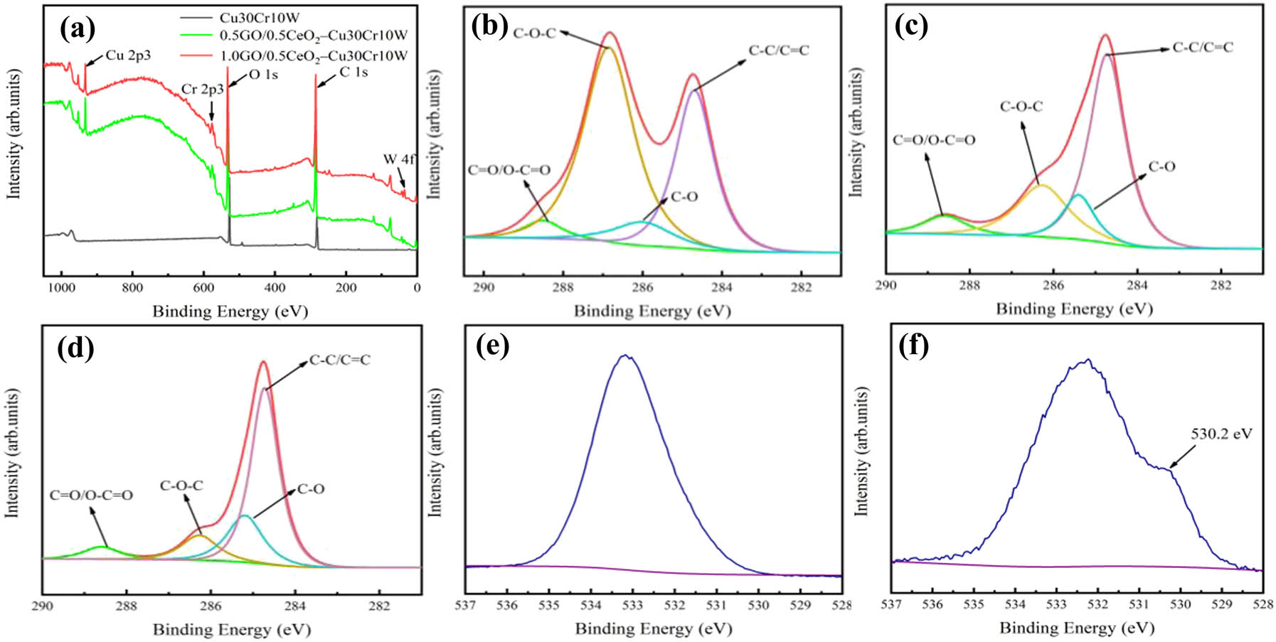
XPS analysis of the two as-sintered composites: (a) XPS spectra of GO and two kinds of composites; peak separation fitting of C 1s spectrum of (b) GO, (c) 0.5GO/0.5CeO2–Cu30Cr10W, and (d) 1.0GO/0.5CeO2–Cu30Cr10W; O 1s spectra of GO (e) and composites (f).
3.3 Comprehensive properties of composite materials
The density, Vickers hardness, and conductivity of the composites are listed in Table 1. By calculation, the relative density of 0.5GO/0.5CeO2–Cu30Cr10W and 1.0 GO/0.5CeO2–Cu30Cr10W composites is above 98%. In addition, compared with the Cu30Cr10W composite prepared under the same conditions, the electrical conductivity of the two composites containing graphene is increased by 16.8 and 10%, respectively. Although the existence of functional groups in GO will weaken the electrical conductivity, some functional groups will be reduced during the sintering process, which makes graphene oxide transform into reduced graphene oxide with excellent electrical conductivity. According to XPS results, GO will not be completely transformed into rGO. However, rGO can significantly improve the conductivity of the material. Therefore, the conductivity of GO-doped composites will be significantly improved. However, when 1 wt% GO is doped, the conductivity decreases due to the agglomeration of GO. In addition, the Vickers hardness of GO-doped composites is increased by 16 and 19.6%, respectively.
Comprehensive properties of composites
| Composite | Relative density (%) | Electrical conductivity (%IACS) | Vickers hardness (HV) | Tensile strength (MPa) |
|---|---|---|---|---|
| Cu30Cr10W0.5CeO2 | 97.41 | 54.6 | 111.34 | 262 |
| 0.5GO/0.5CeO2–Cu30Cr10W | 98.75 | 63.8 | 129.05 | 387 |
| 1.0GO/0.5CeO2–Cu30Cr10W | 98.43 | 60.4 | 133.16 | 358 |
Welding characteristics of electrical contact materials are closely related to the strength of materials, and the welding force decreases when tensile strength decreases [7]. Nevertheless, when the strength is lower than the threshold value, the wear resistance of electrical contact materials will be reduced, thus accelerating the failure of electrical contact materials [37]. Figure 4 shows the stress–strain curve of the studied material. The tensile strength of the three composites is 262, 387, and 358 MPa, respectively. The tensile strength of the composites with the strengthening phase is increased by 47 and 36%, respectively. The main reason behind this is that the strong bond between the functional groups of graphene oxide and copper provides their strong adhesion, graphene oxide transforms into reduced graphene oxide under the action of high discharge temperature, and rGO causes the redistribution effect of high load [19]. In addition, part of the carbon atoms and chromium form Cr3C2 nanoparticles, which enhance the interface bonding. Moreover, CeO2 nanoparticles hinder the movement of dislocations, resulting in the stacking of dislocations, which improves the mechanical strength.
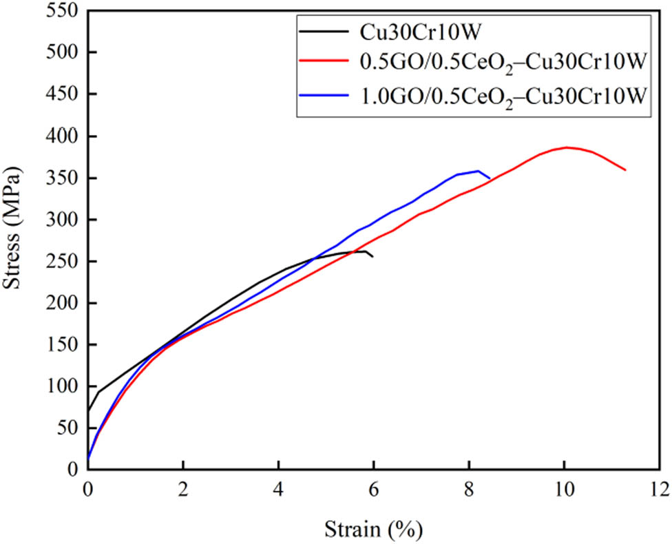
Tensile stress–strain curves of different composites.
3.4 SEM and TEM analysis
SEM images of the 0.5GO/0.5CeO2–Cu30Cr10W and 1.0GO/0.5CeO2–Cu30Cr10W composites are shown in Figure 5. Cr particles are evenly distributed in the copper matrix, while tungsten particles are slightly agglomerated, the carbon element dispersed on the metal matrix, and the components of the composite did not have obvious oxidation behavior. The surface of the matrix is compact without obvious defects.
SEM images and corresponding EDS maps of the two composites: (a, c, and e) 0.5GO/0.5CeO2–Cu30Cr10W; (b, d, and f) 1.0GO/0.5CeO2–Cu30Cr10W.
Figure 6 shows the TEM and HRTEM images of the 0.5GO/0.5CeO2–Cu30Cr10W composite. This is a typical deformation microstructure, including dislocation entanglement and twinning. The entanglement of dislocations and the formation of dislocation packets can be seen in Figure 6(a), which significantly improves the strength of the copper matrix. As shown in Figure 6(c), cerium oxide nanoparticles are dispersed on the rGO. Twins are formed in the copper matrix after plasma sintering, which is of great help to improve the elongation of the composite material. However, this is not the contribution of the twin itself, but because the twin changes the phase of the crystal, leading to the start of the new slip system, which indirectly contributes to the deformation of the statue.
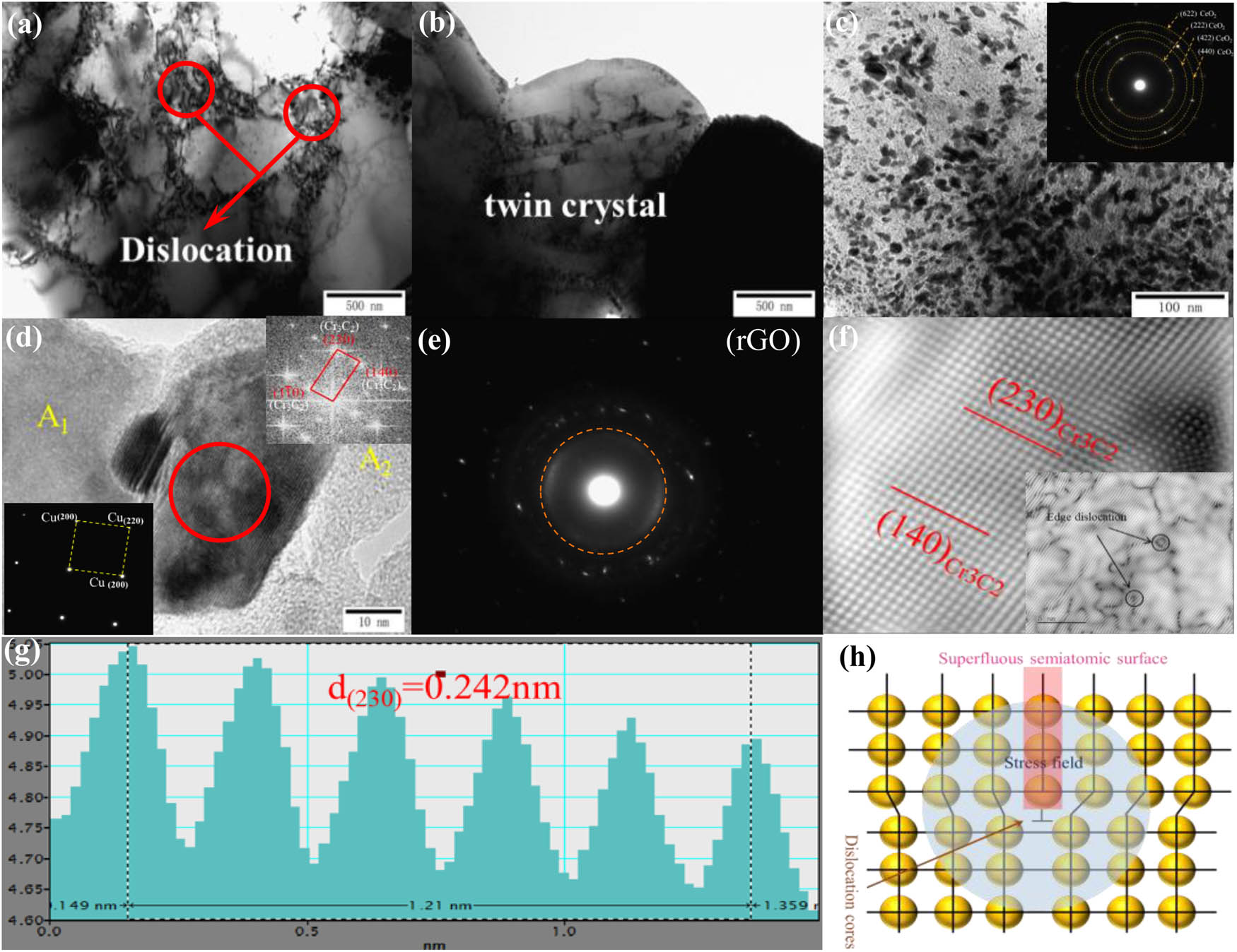
TEM and HRTEM images of 0.5GO/0.5CeO2–Cu30Cr10W composite; (a–c) bright field image; (d and f) HRTEM and diffraction spots image of Cr3C2 and Cu; (e) dark field image showing the rGO; (g) gray-scale spectrogram of vertical direction of crystal plane; and (h) diagram of edge dislocation.
Fourier transforms the selected A1 and A2 regions in Figure 6(d). Copper and rGO were identified, which perfectly matched the XPS test results of the existing state of carbon atoms. The particles formed in situ between copper and rGO can be identified as Cr3C2 in Figure 6(d and e) by fast Fourier transform analysis. Figure 6(f) shows the orientation of two crystal planes of Cr3C2 with orthorhombic structure:
3.5 Arc ablation morphology
Arc ablation refers to the discharge between two contacts in the process of circuit making and breaking contact and produces a lot of arc heat, which leads to the increase of contact temperature. The contact surface material melts and flows under the action of heat flow, and the flowing liquid metal will separate the components of the composite material [52,53]. Serious arc ablation will lead to material evaporation, sputtering and contact deformation, and then failure. Figure 7 shows the low power images and corresponding three-position profiles of the two kinds of doped graphene and ceria contact materials after 25 V, 30 A, and 5,000 switching cycles. Canyon-like pits and mountain-like protrusions appear on the surface of the anode and cathode, respectively, which indicate that the material on the contact surface migrates from cathode to anode.
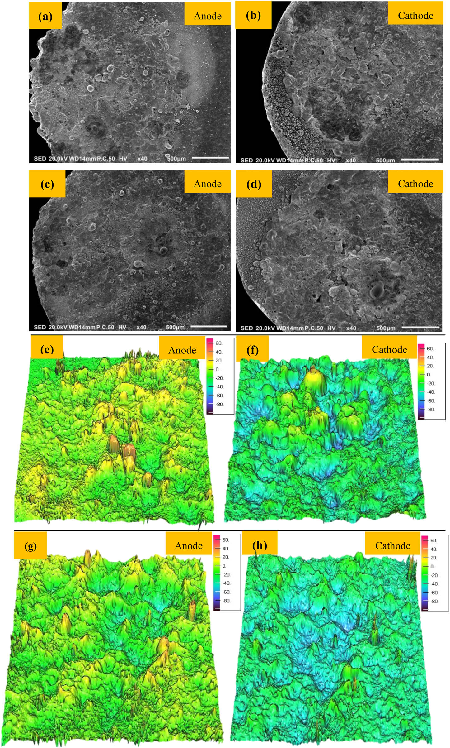
SEM images of arc erosion morphology and corresponding 3D profiles (a, b, e, and f) 0.5GO/0.5CeO2–Cu30Cr10W; (c, d, g, and h) 1.0GO/0.5CeO2–Cu30Cr10W.
Figure 8 shows the high-power arc ablation morphology and EDS analysis results of 0.5GO/0.5CeO2–Cu30Cr10W contact material. Figure 8(a)–(d) shows typical arc ablation patterns such as dispersed droplets, peak-like protrusions, and coral-like structures on the contact surface. As shown in Figure 8(a), due to the high temperature generated by the arc, the copper with a low melting point will melt preferentially, and the liquid copper will splash to the low-temperature area of the contact and solidify. Cr particles strongly absorb oxygen at high temperature, forming the small particles of chromium oxide in Figure 8(c). Due to the flow and splash of liquid metal and the fracture of the liquid metal bridge when the contact is disconnected, the composition distribution on the contact surface is uneven. Moreover, the accumulation of refractory metals leads to the appearance of a coral-like structure, as seen in Figure 8(d).
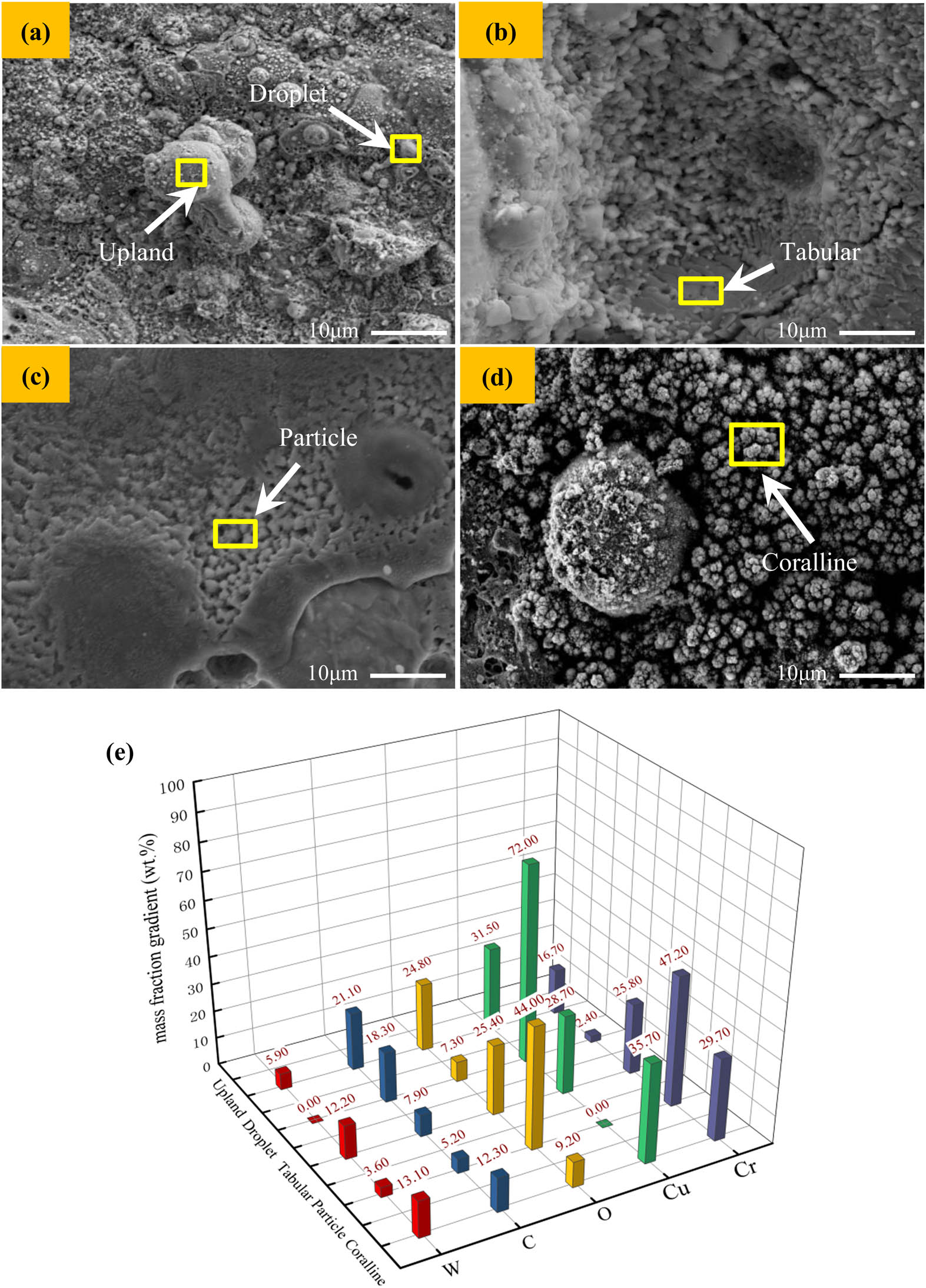
SEM image and EDS analysis of typical characteristics of electrical contact: (a) droplet and upland; (b) tabular; (c) particle; (d) coralline; (e) EDS data.
4 Discussion
4.1 Morphology evolution and mass transfer of arc erosion
A large number of migrations and loss of anode and cathode materials are fatal to electrical contacts, which will directly affect the service life of components. Figure 9 shows the results of the quality change of the electrical contact material after the electrical contact test at 25 V DC and 10–30 A. The electrode materials migrate from cathode to anode. The total mass of the electrode shows a decreasing trend compared with that before the electrical contact test, and this trend becomes more and more obvious with the increase of the current, which indicates that the electrode material diffuses to the surrounding environment. In the process of contact opening and closing, there are two stages: the formation of a melting bridge and the formation of an arc. According to previous reports, the arc mainly experienced the metal phase and gas phase [54].
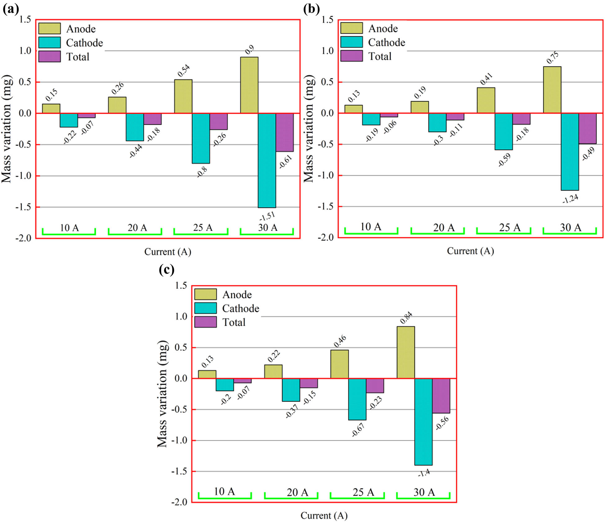
(a) Mass change of the Cu30Cr10W composite, (b) mass change of the 0.5GO/0.5CeO2–Cu30Cr10W composite, and (c) mass change of the 1.0GO/0.5CeO2–Cu30Cr10W composite.
Under the action of an external electric field, a large amount of heat melts the material. When the electrical contact is disconnected, the molten liquid bridge will be formed. When the electrical contact is further disconnected, the liquid bridge will be randomly disconnected, resulting in the uneven migration of the electrode material to the electrode contact surface. The vaporized metal particles in the contact gap ionize and generate an arc. Due to the further influence of the electric field, metal ions are produced in the process of the collision between the electrons emitted from the cathode and the metal vapor, leading to the migration of a small amount of electrode materials from the anode to the cathode. During the arc discharge progress process, the properties of the arc change substantially. This is because the gas in the environment enters the arc and becomes the main ionized plasma column, which leads to the transformation of arc properties from metal arc to gas arc [55,56]. The falling gas particles bombard the cathode surface, resulting in a large amount of erosion of cathode contact surface materials. At the same time, the contraction of the arc in the cathode region increases the heat flux into the cathode, and the cathode surface material will be more eroded than the anode. Therefore, the net anode gain can be observed instead of the migration of anode material to the cathode.
Reduced graphene oxide will increase the viscosity of molten metal, and the density of reduced graphene oxide is smaller than the molten metal, so it will float on the surface of flowing molten metal, which is conducive to stabilizing the molten pool, inhibiting the flow and splashing of molten metal, to reduce arc erosion. In addition, composite resulted in favorable mechanical and thermal property, which suppressed the mass loss under arc erosion [57]. At the same time, the mass transfer and mass loss of the electrical contact doped with 0.5 wt% GO are optimal under each test current condition. This is because the conductivity of the other two kinds of electrical contact materials is low, and the heat generated by the arc will directly lead to the aggravation of arc erosion.
4.2 The relationship between welding force, strength, and arcing energy
When the contacts split and close the circuit, the arc discharge will occur when the arcing condition is satisfied, which leads to arc erosion on the contact surface of the electric contacts, accompanied by electric contact physical phenomena such as arc energy and fusion welding force [54]. In the interaction between the arc and the contact, the arc inputs energy to the contact, so that the contact is heated and melted, forming a molten pool. When the molten metal solidifies, it is easy to weld the contact, so that it cannot be disconnected. Welding is one of the main forms of contact failure. The force that separates the welding contact is called the fusion welding force. Figures 10 and 11 show the variation of arc burning energy and welding force of different composites under 25 V DC and 10–30 A test conditions. The results indicate that the arc burning energy and welding force of the composite is significantly reduced with the strengthening phase. It should be noted that the 1.0GO/0.5CeO2–Cu30Cr10W composite has the minimum arc energy and welding force under each test condition. This is because GO and nano-CeO2 disperse the arc and improve the arc extinguishing ability of the material. There is a close relationship between the welding force, arc energy, and tensile strength. It is necessary to clarify the relationship between the arc energy, tensile strength, and welding force in order to solve the problem of contact failure. According to the mathematical evaluation model of the welding force [58], it can be expressed as follows:
where F m represents the maximum welding force, K is the coefficient of contact material, and W is the sum of arc energy and Joule heat. It is generally believed that the energy produced by the arc is much greater than Joule heat, so the total energy W can be equal to the arc energy. The total energy input into the contact area of the contact and the coefficient K are as follows:
where V A and V C are the current and voltage loaded at both ends of the electrical contact material, respectively; W C and W A are Joule heat and arc energy, respectively; Г and δ represent the ultimate tensile strength of the electrical contact material and the density of the molten material, respectively; T m and T b are the melting point and initial temperature, respectively; and C L and C V are the melting latent heat and specific heat. For the three composites, the relative density and specific heat C V are almost the same. Therefore, the ratio of contact material coefficient K is close to the ratio of ultimate tensile strength. Therefore, it can be concluded from the analysis of the expression that the maximum welding force F m is related to the arc energy W A and the tensile strength Γ. From this, one can get the mathematical expression for the maximum welding force:
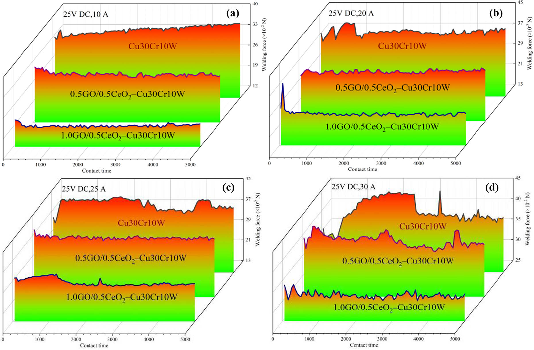
Welding forces of different composites at (a) 25 V DC, 10 A, (b) 25 V DC, 20 A, (c) 25 V DC, 25 A, and (d) 25 V DC, 30 A.
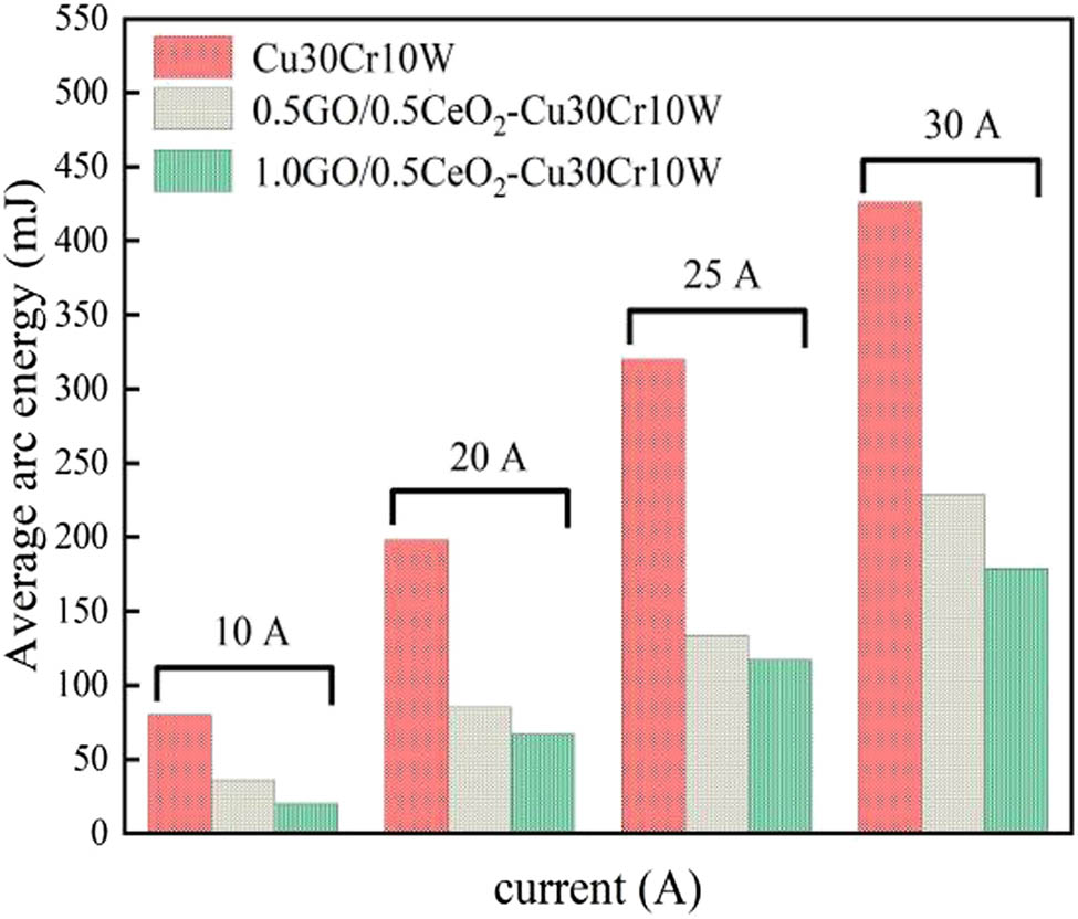
Arc burning energy of composite materials.
Here, N is a constant. The welding force is determined by the tensile strength and the arc energy. The Γ of Cu30Cr10W and 1.0GO/0.5CeO2–Cu30Cr10W are 262 and 358 MPa, respectively. The average arc energy is 198 and 67 mJ at 25 V DC and 20 A, respectively. From formula (6) calculation, it can be concluded that the welding force of Cu30Cr10W composite is 1.5 times that of 1.0GO/0.5CeO2–Cu30Cr10W composite, which can verify that the theoretical calculation results are consistent with the experimental results (37.29 and 25.24 cN). Based on the analysis of formula (6), the arc energy plays a dominant role in determining the welding force. Therefore, in situ graphene doped with nano-CeO2 can play an important role in reducing the welding force.
5 Conclusions
Freeze-drying retained the structure of graphene oxide to the greatest extent and reduced the degree of agglomeration. In the process of the high-temperature sintering, GO transforms to rGO, and rGO causes the redistribution effect of load. Cr3C2 particles formed in situ at the interface of rGO–Cu enhance the interface bonding. CeO2 nanoparticles not only improve the mechanical strength but also do not degrade electrical conductivity. The tensile strength of the composites doped with the strengthening phase is increased by 47 and 36%, respectively. In addition, twins also play an active role in plastic deformation.
Arc energy and tensile strength affect the welding force, and the arc energy is the dominant factor. The arc energy of the material decreases with the addition of the reinforcing phase, and 1.0GO/0.5CeO2–Cu30Cr10W has the best welding resistance. At the same time, the cathode materials migrate to the anode, and reduced graphene oxide can inhibit the flow of molten metal and weaken the splash.
At present, researchers have understood the effect of graphene on the mechanical and electrical properties of copper-based materials and have a preliminary understanding of the reinforcement mechanism. In the next stage, we focus on the research of go surface modification, focusing on improving the dispersion of go, and deeply studying the strengthening mechanism of graphene in copper matrix composites, especially in the field of electrical contact.
-
Funding information: This work was supported by the National Natural Science Foundation of China (52071134), Natural Science Foundation of Henan Province (202300410144), Key Scientific Research Projects of Higher Education in Henan Province (21A430013), and Outstanding Talents Innovation Fund of Henan Province (ZYQR201912164).
-
Author contributions: All authors have accepted responsibility for the entire content of this manuscript and approved its submission.
-
Conflict of interest: The authors state no conflict of interest.
References
[1] Zhang XH , Zhang Y , Tian BH , Song KX , Liu P , Jia YL , et al. Review of nano-phase effects in high strength and conductivity copper alloys. Nanotechnol Rev. 2019;8(1):383–95.10.1515/ntrev-2019-0034Suche in Google Scholar
[2] Yang P , You X , Yi JH , Fang D , Bao R , Shen T , et al. Simultaneous achievement of high strength, excellent ductility, and good electrical conductivity in carbon nanotube/copper composites. J Alloy Compd. 2018;752:431–9.10.1016/j.jallcom.2018.03.341Suche in Google Scholar
[3] Rasool MD , Kamran B , Safaei B , Qin ZY . Static performance of agglomerated CNT-reinforced porous plates bonded with piezoceramic faces. Int J Mech Sci. 2020;188:105966.10.1016/j.ijmecsci.2020.105966Suche in Google Scholar
[4] Li TJ , Wang YQ , Yang M , Hou HL , Wu SJ . High strength and conductivity copper matrix composites reinforced by in situ graphene through severe plastic deformation processes. J Alloy Compd. 2021;851:156703.10.1016/j.jallcom.2020.156703Suche in Google Scholar
[5] Rajkovic V , Bozic D , Stasic J , Wang HW , Jovanovic M . Processing, characterization and properties of copper-based composites strengthened by low amount of alumina particles. Powder Technol. 2014;268:392–400.10.1016/j.powtec.2014.08.051Suche in Google Scholar
[6] Safaei B . The effect of embedding a porous core on the free vibration behavior of laminated composite plates. Steel Compos Struct. 2020;35(5):659–70.Suche in Google Scholar
[7] Lin HR , Guo XH , Song KX , Feng J , Li SL , Zhang XF . Synergistic strengthening mechanism of copper matrix composite reinforced with nano-Al2O3 particles and micro-SiC whiskers. Nanotechnol Rev. 2021;10(1):62–72.10.1515/ntrev-2021-0006Suche in Google Scholar
[8] Li HY , Wang XH , Hu ZD , Liu YF . Investigation of arc erosion mechanism for tin dioxide-reinforced silver-based electrical contact material under direct current. J Electron Mater. 2020;49:4730–40.10.1007/s11664-020-08193-9Suche in Google Scholar
[9] Sahmani S , Safaei B . Large-amplitude oscillations of composite conical nanoshells with in-plane heterogeneity including surface stress effect. Appl Math Model. 2021;89:1792–813.10.1016/j.apm.2020.08.039Suche in Google Scholar
[10] Sadoun AM , Fathy A . Experimental study on tribological properties of Cu-Al2O3 nanocomposite hybridized by graphene nanoplatelets. Ceram Int. 2019;45(18):24784–92.10.1016/j.ceramint.2019.08.220Suche in Google Scholar
[11] Qin YQ , Wu YC , Wang DB , Li P , Huang XM , Zheng YC . Influence of SiC particle size on the wear properties of SiC/Cu composites. Adv Mater Res. 2011;1378:635–9.10.4028/www.scientific.net/AMR.311-313.635Suche in Google Scholar
[12] Zhu XY , Zhang J , Chen JL , Wu Y . Structure and properties of W-Cu/AlN composites prepared via a hot press-sintering method. Rare Met Mater Eng. 2015;44(11):2661–4.10.1016/S1875-5372(16)60014-0Suche in Google Scholar
[13] Tran VN , Yang S , Phung TA . Microstructure and properties of Cu/TiB2 wear resistance composite coating on H13 steel prepared by in situ laser cladding. Opt Laser Technol. 2018;108:480–6.10.1016/j.optlastec.2018.07.036Suche in Google Scholar
[14] Lee JS , Kim YC , Lee S , Kim NJ , Ahn SA . Correlation of the microstructure and mechanical properties of oxide-dispersion-strengthened coppers fabricated by internal oxidation. Metall Mater Trans A. 2004;35(2):493–502.10.1007/s11661-004-0360-9Suche in Google Scholar
[15] Fu YB , Pan QF , Cao ZQ , Li SF , Huo YQ . Strength and electrical conductivity behavior of nanoparticles reaction on new alumina dispersion-strengthened copper alloy. J Alloy Compd. 2019;798:616–21.10.1016/j.jallcom.2019.05.271Suche in Google Scholar
[16] Ahmad SI , Hamoudi H , Abdala A , Ghouri ZK , Youssef KM . Graphene-reinforced bulk metal matrix composites: synthesis, microstructure, and properties. Rev Adv Mater Sci. 2020;59(1):67–114.10.1515/rams-2020-0007Suche in Google Scholar
[17] Qiao ZJ , Zhou T , Kang JL , Yu ZY , Zhang GL , Li M , et al. Three-dimensional interpenetrating network graphene/copper composites with simultaneously enhanced strength, ductility and conductivity. Mater Lett. 2018;224:37–41.10.1016/j.matlet.2018.04.069Suche in Google Scholar
[18] Liu CJ , Huang XH , Wu YY , Deng XW , Liu J , Zheng ZL , et al. Review on the research progress of cement-based and geopolymer materials modified by graphene and graphene oxide. Nanotechnol Rev. 2020;9(1):155–69.10.1515/ntrev-2020-0014Suche in Google Scholar
[19] Hwang J , Yoon T , Jin SH , Lee J , Kim TS , Hong SH , et al. Enhanced mechanical properties of graphene/copper nanocomposites using a molecular‐level mixing process. Adv Mater. 2013;25(46):6724–9.10.1002/adma.201302495Suche in Google Scholar PubMed
[20] Edwards RS , Coleman KS . Graphene synthesis: relationship to applications. Nanoscale. 2013;5(1):38–51.10.1039/C2NR32629ASuche in Google Scholar
[21] Li L , Zhang JC , Su HS , Li JY , Sun LZ , Wang ZH , et al. Towards super-clean graphene. Nat Commun. 2019;10(1):1362–4.10.1038/s41467-019-09565-4Suche in Google Scholar
[22] Bolotin KI , Sikes KJ , Jiang Z , Klima M , Fudenberg G , Hone J , et al. Ultrahigh electron mobility in suspended graphene. Solid State Commun. 2008;146(9):351–5.10.1016/j.ssc.2008.02.024Suche in Google Scholar
[23] Lee CG , Wei XD , Kysar JW , Hone J . Measurement of the elastic properties and intrinsic strength of monolayer graphene. Science. 2008;321(5887):385–8.10.1126/science.1157996Suche in Google Scholar PubMed
[24] Cai CL , Wang T , Qu GW , Feng ZQ . High thermal conductivity of graphene and structure defects: prospects for thermal applications in graphene sheets. Chin Chem Lett. 2020;32(4):1293–98.10.1016/j.cclet.2020.10.030Suche in Google Scholar
[25] Du X , Skachko I , Barker A , Andrei EY . Approaching ballistic transport in suspended graphene. Nat Nanotechnol. 2008;3(8):491–5.10.1038/nnano.2008.199Suche in Google Scholar PubMed
[26] Wang Y , Feng JQ , Jin LH , Li CS . Photocatalytic reduction of graphene oxide with cuprous oxide film under UV-Vis irradiation. Rev Adv Mater Sci. 2020;59(1):207–14.10.1515/rams-2020-0022Suche in Google Scholar
[27] Katarzyna K , Magdalena O , Karolina O . Preparation and properties of composite materials containing graphene structures and their applicability in personal protective equipment: a review. Rev Adv Mater Sci. 2020;59(1):215–42.10.1515/rams-2020-0025Suche in Google Scholar
[28] Haneul J , Seonghyeon Y , Quevedo M , Choi H . Effect of processing route on mechanical and thermal properties of few-layered graphene (FLG)-reinforced copper matrix composites. J Alloy Compd. 2018;754:7–13.10.1016/j.jallcom.2018.04.272Suche in Google Scholar
[29] Xie BH , Sahmani S , Safaei B , Bin X . Nonlinear secondary resonance of FG porous silicon nanobeams under periodic hard excitations based on surface elasticity theory. Eng Comput. 2020;37(2):1611–34.10.1007/s00366-019-00931-wSuche in Google Scholar
[30] Hashim H , Salleh MS , Omar MZ . Homogenous dispersion and interfacial bonding of carbon nanotube reinforced with aluminum matrix composite: a review. Rev Adv Mater Sci. 2019;51(1):295–303.10.1515/rams-2019-0035Suche in Google Scholar
[31] Liu CJ , Huang XC , Wu YY , Deng XW , Zheng ZL , Xu Z , et al. Advance on the dispersion treatment of graphene oxide and the graphene oxide modified cement-based materials. Nanotechnol Rev. 2021;10(1):34–9.10.1515/ntrev-2021-0003Suche in Google Scholar
[32] Saboori A , Pavese M , Badini C , Fino P . Microstructure and thermal conductivity of Al–graphene composites fabricated by powder metallurgy and hot rolling techniques. Acta Metall Sin (Engl Lett). 2017;30(07):675–87.10.1007/s40195-017-0579-2Suche in Google Scholar
[33] Fan F , Xu YB , Sahmani S , Safaei B . Modified couple stress-based geometrically nonlinear oscillations of porous functionally graded microplates using NURBS-based isogeometric approach. Comput Methods Appl Mech Eng. 2020;372:113400.10.1016/j.cma.2020.113400Suche in Google Scholar
[34] Liu CJ , Huang XC , Wu YY , Deng XW , Zheng ZL . The effect of graphene oxide on the mechanical properties, impermeability and corrosion resistance of cement mortar containing mineral admixtures. Constr Build Mater. 2021;288:123059.10.1016/j.conbuildmat.2021.123059Suche in Google Scholar
[35] Zhang X , Wan DQ , Peng K , Zhang W . Enhancement of thermal conductivity and mechanical properties of Cu-reduced graphene oxide composites by interface modification. J Mater Eng Perform. 2019;28(8):5165–71.10.1007/s11665-019-04212-xSuche in Google Scholar
[36] Wang LD , Yang ZY , Cui Y , Wei B , Xu SH , Sheng J , et al. Graphene-copper composite with micro-layered grains and ultrahigh strength. Sci Rep. 2017;7(1):2558–61.10.1038/srep41896Suche in Google Scholar
[37] Chen SH , Fu SL , Liang D , Chen XH , Mi XJ , Liu P , et al. Preparation and properties of 3D interconnected CNTs/Cu composites. Nanotechnol Rev. 2020;9:146–54.10.1515/ntrev-2020-0013Suche in Google Scholar
[38] Zhang XH , Zhang Y , Tian BH , Jia YL , Fu M , Liu Y , et al. Graphene oxide effects on the properties of Al2O3-Cu/35W5Cr composite. J Mater Sci Technol. 2020;37(02):185–99.10.1016/j.jmst.2019.08.014Suche in Google Scholar
[39] Shao GS , Liu P , Li W , Chen XH , Ma FC , Liu XK , et al. Effects of graphene nanoplates on arc erosion resistance and wear behavior under electric current of copper matrix composites. J Alloy Compd. 2020;829:154356.10.1016/j.jallcom.2020.154356Suche in Google Scholar
[40] Wang J , Guo LN , Lin WM , Chen J , Zhang S , Chen SD , et al. The effects of graphene content on the corrosion resistance, and electrical, thermal and mechanical properties of graphene/copper composites. Carbon. 2019;150:551–1.10.1016/j.carbon.2019.04.095Suche in Google Scholar
[41] Chen HP , Cheng JG , Zhang ML , Chen WC , Wei BZ , Chen PQ , et al. Effect of rare earth oxide addition on the microstructure and properties of ultrafine grain W-20Cu composites. Rare Met Mater Eng. 2018;47(9):2626–30.10.1016/S1875-5372(18)30199-1Suche in Google Scholar
[42] Liu CJ , He X , Deng XW , Wu YY , Zheng ZL , Liu J , et al. Application of nanomaterials in ultra-high performance concrete: a review. Nanotechnol Rev. 2020;9(1):1427–44.10.1515/ntrev-2020-0107Suche in Google Scholar
[43] Yan YX , Nashath FZ , Chen S , Manickam S , Lim SS , Zhao HT , et al. Synthesis of graphene: Potential carbon precursors and approaches. Nanotechnol Rev. 2020;9(1):1284–314.10.1515/ntrev-2020-0100Suche in Google Scholar
[44] Lesiak B , Trykowski G , Tóth J , Biniak S , Kövér L , Rangam N , et al. Chemical and structural properties of reduced graphene oxide-dependence on the reducing agent. J Mater Sci. 2021;56(5):3738–54.10.1007/s10853-020-05461-1Suche in Google Scholar
[45] Yang Y , Dai J , Li YJ , Jia MC , Huang XY . Less defective fluorine-containing graphene with good dispersity: preparation, characterization, and application in transparent conductive thin film. Carbon. 2017;115:285–92.10.1016/j.carbon.2017.01.021Suche in Google Scholar
[46] Cui P , Lee JH , Eunhee H , Hyoyoung L . One-pot reduction of graphene oxide at subzero temperatures. Chem Commun. 2011;47(45):12370–2.10.1039/c1cc15569eSuche in Google Scholar PubMed
[47] Maria C , Florina P , Alexandru T , Monica D , Camelia BG , Ovidiu PI , et al. Green synthesis, characterization and potential application of reduced graphene oxide. Phys E: Low-dimensional Syst Nanostructures. 2020;119:113971.10.1016/j.physe.2020.113971Suche in Google Scholar
[48] Min CY , He ZB , Liu DD , Jia W , Qian JM , Jin YH , et al. Ceria/reduced graphene oxide nanocomposite: synthesis, characterization, and its lubrication application. ChemistrySelect. 2019;4(15):4615–23.10.1002/slct.201900862Suche in Google Scholar
[49] Pachfule P , Shinde D , Majumder M , Xu Q . Fabrication of carbon nanorods and graphene nanoribbons from a metal-organic framework. Nat Chem. 2016;8(7):718–24.10.1038/nchem.2515Suche in Google Scholar PubMed
[50] Chen XF , Tao JM , Yi JH , Liu YC , Li CJ , Bao R . Strengthening behavior of carbon nanotube-graphene hybrids in copper matrix composites. Mater Sci Eng A. 2018;718:427–36.10.1016/j.msea.2018.02.006Suche in Google Scholar
[51] Shi MM , Bao D , Li SJ , Wulan BR , Yan JM , Jiang Q . Anchoring PdCu amorphous nanocluster on graphene for electrochemical reduction of N2 to NH3 under ambient conditions in aqueous solution. Adv Energy Mater. 2018;8:21.10.1002/aenm.201800124Suche in Google Scholar
[52] Guo YL , Zhou ZB , Wang YP . Preparation, electrical contact performance and arc-erosion behavior of Cu/La2NiO4 composites. Proceedings of the 3rd International Conference on Material. Mechanical and Manufacturing Engineering; 2015.10.2991/ic3me-15.2015.294Suche in Google Scholar
[53] Li AK , Zhou WY , Xie M , Wang SB , Wang SB , Yang YC , et al. Preparation and arc erosion behavior of AgNi10 contact material with different allotropes of carbon addition. Diam Relat Mater. 2020;111:108141.10.1016/j.diamond.2020.108141Suche in Google Scholar
[54] Li HY , Wang XH , Liu YF , Guo XH . Effect of strengthening phase on material transfer behavior of Ag-based contact materials under different voltages. Vacuum. 2017;135:55–65.10.1016/j.vacuum.2016.10.031Suche in Google Scholar
[55] Long F , Guo XH , Song KX , Jia SG , Yakubov V , Li SL , et al. Enhanced arc erosion resistance of TiB2/Cu composites reinforced with the carbon nanotube network structure. Mater Des. 2019;183:108136.10.1016/j.matdes.2019.108136Suche in Google Scholar
[56] Wang XH , Yang H , Chen M , Zou JT , Liang SH . Fabrication and arc erosion behaviors of AgTiB2 contact materials. Powder Technol. 2014;256:20–4.10.1016/j.powtec.2014.01.068Suche in Google Scholar
[57] Li SL , Guo XH , Zhang SL , Feng J , Song KX , Liang SH . Arc erosion behavior of TiB2/Cu composites with single-scale and dual-scale TiB2 particles. Nanotechnol Rev. 2019;8(1):619–27.10.1515/ntrev-2019-0054Suche in Google Scholar
[58] Slade PG . Electrical contacts: principles and applications. Florida: CRC press; 2017. p. 65–7.10.1201/b15640Suche in Google Scholar
© 2021 Shengli Liang et al., published by De Gruyter
This work is licensed under the Creative Commons Attribution 4.0 International License.
Artikel in diesem Heft
- Research Articles
- Improved impedance matching by multi-componential metal-hybridized rGO toward high performance of microwave absorption
- Pure-silk fibroin hydrogel with stable aligned micropattern toward peripheral nerve regeneration
- Effective ion pathways and 3D conductive carbon networks in bentonite host enable stable and high-rate lithium–sulfur batteries
- Fabrication and characterization of 3D-printed gellan gum/starch composite scaffold for Schwann cells growth
- Synergistic strengthening mechanism of copper matrix composite reinforced with nano-Al2O3 particles and micro-SiC whiskers
- Deformation mechanisms and plasticity of ultrafine-grained Al under complex stress state revealed by digital image correlation technique
- On the deformation-induced grain rotations in gradient nano-grained copper based on molecular dynamics simulations
- Removal of sulfate from aqueous solution using Mg–Al nano-layered double hydroxides synthesized under different dual solvent systems
- Microwave-assisted sol–gel synthesis of TiO2-mixed metal oxide nanocatalyst for degradation of organic pollutant
- Electrophoretic deposition of graphene on basalt fiber for composite applications
- Polyphenylene sulfide-coated wrench composites by nanopinning effect
- Thermal conductivity and thermoelectric properties in 3D macroscopic pure carbon nanotube materials
- An effective thermal conductivity and thermomechanical homogenization scheme for a multiscale Nb3Sn filaments
- Friction stir spot welding of AA5052 with additional carbon fiber-reinforced polymer composite interlayer
- Improvement of long-term cycling performance of high-nickel cathode materials by ZnO coating
- Quantum effects of gas flow in nanochannels
- An approach to effectively improve the interfacial bonding of nano-perfused composites by in situ growth of CNTs
- Effects of nano-modified polymer cement-based materials on the bending behavior of repaired concrete beams
- Effects of the combined usage of nanomaterials and steel fibres on the workability, compressive strength, and microstructure of ultra-high performance concrete
- One-pot solvothermal synthesis and characterization of highly stable nickel nanoparticles
- Comparative study on mechanisms for improving mechanical properties and microstructure of cement paste modified by different types of nanomaterials
- Effect of in situ graphene-doped nano-CeO2 on microstructure and electrical contact properties of Cu30Cr10W contacts
- The experimental study of CFRP interlayer of dissimilar joint AA7075-T651/Ti-6Al-4V alloys by friction stir spot welding on mechanical and microstructural properties
- Vibration analysis of a sandwich cylindrical shell in hygrothermal environment
- Water barrier and mechanical properties of sugar palm crystalline nanocellulose reinforced thermoplastic sugar palm starch (TPS)/poly(lactic acid) (PLA) blend bionanocomposites
- Strong quadratic acousto-optic coupling in 1D multilayer phoxonic crystal cavity
- Three-dimensional shape analysis of peripapillary retinal pigment epithelium-basement membrane layer based on OCT radial images
- Solvent regulation synthesis of single-component white emission carbon quantum dots for white light-emitting diodes
- Xanthate-modified nanoTiO2 as a novel vulcanization accelerator enhancing mechanical and antibacterial properties of natural rubber
- Effect of steel fiber on impact resistance and durability of concrete containing nano-SiO2
- Ultrasound-enhanced biosynthesis of uniform ZnO nanorice using Swietenia macrophylla seed extract and its in vitro anticancer activity
- Temperature dependence of hardness prediction for high-temperature structural ceramics and their composites
- Study on the frequency of acoustic emission signal during crystal growth of salicylic acid
- Controllable modification of helical carbon nanotubes for high-performance microwave absorption
- Role of dry ozonization of basalt fibers on interfacial properties and fracture toughness of epoxy matrix composites
- Nanosystem’s density functional theory study of the chlorine adsorption on the Fe(100) surface
- A rapid nanobiosensing platform based on herceptin-conjugated graphene for ultrasensitive detection of circulating tumor cells in early breast cancer
- Improving flexural strength of UHPC with sustainably synthesized graphene oxide
- The role of graphene/graphene oxide in cement hydration
- Structural characterization of microcrystalline and nanocrystalline cellulose from Ananas comosus L. leaves: Cytocompatibility and molecular docking studies
- Evaluation of the nanostructure of calcium silicate hydrate based on atomic force microscopy-infrared spectroscopy experiments
- Combined effects of nano-silica and silica fume on the mechanical behavior of recycled aggregate concrete
- Safety study of malapposition of the bio-corrodible nitrided iron stent in vivo
- Triethanolamine interface modification of crystallized ZnO nanospheres enabling fast photocatalytic hazard-free treatment of Cr(vi) ions
- Novel electrodes for precise and accurate droplet dispensing and splitting in digital microfluidics
- Construction of Chi(Zn/BMP2)/HA composite coating on AZ31B magnesium alloy surface to improve the corrosion resistance and biocompatibility
- Experimental and multiscale numerical investigations on low-velocity impact responses of syntactic foam composites reinforced with modified MWCNTs
- Comprehensive performance analysis and optimal design of smart light pole for cooperative vehicle infrastructure system
- Room temperature growth of ZnO with highly active exposed facets for photocatalytic application
- Influences of poling temperature and elongation ratio on PVDF-HFP piezoelectric films
- Large strain hardening of magnesium containing in situ nanoparticles
- Super stable water-based magnetic fluid as a dual-mode contrast agent
- Photocatalytic activity of biogenic zinc oxide nanoparticles: In vitro antimicrobial, biocompatibility, and molecular docking studies
- Hygrothermal environment effect on the critical buckling load of FGP microbeams with initial curvature integrated by CNT-reinforced skins considering the influence of thickness stretching
- Thermal aging behavior characteristics of asphalt binder modified by nano-stabilizer based on DSR and AFM
- Building effective core/shell polymer nanoparticles for epoxy composite toughening based on Hansen solubility parameters
- Structural characterization and nanoscale strain field analysis of α/β interface layer of a near α titanium alloy
- Optimization of thermal and hydrophobic properties of GO-doped epoxy nanocomposite coatings
- The properties of nano-CaCO3/nano-ZnO/SBR composite-modified asphalt
- Three-dimensional metallic carbon allotropes with superhardness
- Physical stability and rheological behavior of Pickering emulsions stabilized by protein–polysaccharide hybrid nanoconjugates
- Optimization of volume fraction and microstructure evolution during thermal deformation of nano-SiCp/Al–7Si composites
- Phase analysis and corrosion behavior of brazing Cu/Al dissimilar metal joint with BAl88Si filler metal
- High-efficiency nano polishing of steel materials
- On the rheological properties of multi-walled carbon nano-polyvinylpyrrolidone/silicon-based shear thickening fluid
- Fabrication of Ag/ZnO hollow nanospheres and cubic TiO2/ZnO heterojunction photocatalysts for RhB degradation
- Fabrication and properties of PLA/nano-HA composite scaffolds with balanced mechanical properties and biological functions for bone tissue engineering application
- Investigation of the early-age performance and microstructure of nano-C–S–H blended cement-based materials
- Reduced graphene oxide coating on basalt fabric using electrophoretic deposition and its role in the mechanical and tribological performance of epoxy/basalt fiber composites
- Effect of nano-silica as cementitious materials-reducing admixtures on the workability, mechanical properties and durability of concrete
- Machine-learning-assisted microstructure–property linkages of carbon nanotube-reinforced aluminum matrix nanocomposites produced by laser powder bed fusion
- Physical, thermal, and mechanical properties of highly porous polylactic acid/cellulose nanofibre scaffolds prepared by salt leaching technique
- A comparative study on characterizations and synthesis of pure lead sulfide (PbS) and Ag-doped PbS for photovoltaic applications
- Clean preparation of washable antibacterial polyester fibers by high temperature and high pressure hydrothermal self-assembly
- Al 5251-based hybrid nanocomposite by FSP reinforced with graphene nanoplates and boron nitride nanoparticles: Microstructure, wear, and mechanical characterization
- Interlaminar fracture toughness properties of hybrid glass fiber-reinforced composite interlayered with carbon nanotube using electrospray deposition
- Microstructure and life prediction model of steel slag concrete under freezing-thawing environment
- Synthesis of biogenic silver nanoparticles from the seed coat waste of pistachio (Pistacia vera) and their effect on the growth of eggplant
- Study on adaptability of rheological index of nano-PUA-modified asphalt based on geometric parameters of parallel plate
- Preparation and adsorption properties of nano-graphene oxide/tourmaline composites
- A study on interfacial behaviors of epoxy/graphene oxide derived from pitch-based graphite fibers
- Multiresponsive carboxylated graphene oxide-grafted aptamer as a multifunctional nanocarrier for targeted delivery of chemotherapeutics and bioactive compounds in cancer therapy
- Piezoresistive/piezoelectric intrinsic sensing properties of carbon nanotube cement-based smart composite and its electromechanical sensing mechanisms: A review
- Smart stimuli-responsive biofunctionalized niosomal nanocarriers for programmed release of bioactive compounds into cancer cells in vitro and in vivo
- Photoremediation of methylene blue by biosynthesized ZnO/Fe3O4 nanocomposites using Callistemon viminalis leaves aqueous extract: A comparative study
- Study of gold nanoparticles’ preparation through ultrasonic spray pyrolysis and lyophilisation for possible use as markers in LFIA tests
- Review Articles
- Advance on the dispersion treatment of graphene oxide and the graphene oxide modified cement-based materials
- Development of ionic liquid-based electroactive polymer composites using nanotechnology
- Nanostructured multifunctional electrocatalysts for efficient energy conversion systems: Recent perspectives
- Recent advances on the fabrication methods of nanocomposite yarn-based strain sensor
- Review on nanocomposites based on aerospace applications
- Overview of nanocellulose as additives in paper processing and paper products
- The frontiers of functionalized graphene-based nanocomposites as chemical sensors
- Material advancement in tissue-engineered nerve conduit
- Carbon nanostructure-based superhydrophobic surfaces and coatings
- Functionalized graphene-based nanocomposites for smart optoelectronic applications
- Interfacial technology for enhancement in steel fiber reinforced cementitious composite from nano to macroscale
- Metal nanoparticles and biomaterials: The multipronged approach for potential diabetic wound therapy
- Review on resistive switching mechanisms of bio-organic thin film for non-volatile memory application
- Nanotechnology-enabled biomedical engineering: Current trends, future scopes, and perspectives
- Research progress on key problems of nanomaterials-modified geopolymer concrete
- Smart stimuli-responsive nanocarriers for the cancer therapy – nanomedicine
- An overview of methods for production and detection of silver nanoparticles, with emphasis on their fate and toxicological effects on human, soil, and aquatic environment
- Effects of chemical modification and nanotechnology on wood properties
- Mechanisms, influencing factors, and applications of electrohydrodynamic jet printing
- Application of antiviral materials in textiles: A review
- Phase transformation and strengthening mechanisms of nanostructured high-entropy alloys
- Research progress on individual effect of graphene oxide in cement-based materials and its synergistic effect with other nanomaterials
- Catalytic defense against fungal pathogens using nanozymes
- A mini-review of three-dimensional network topological structure nanocomposites: Preparation and mechanical properties
- Mechanical properties and structural health monitoring performance of carbon nanotube-modified FRP composites: A review
- Nano-scale delivery: A comprehensive review of nano-structured devices, preparative techniques, site-specificity designs, biomedical applications, commercial products, and references to safety, cellular uptake, and organ toxicity
- Effects of alloying, heat treatment and nanoreinforcement on mechanical properties and damping performances of Cu–Al-based alloys: A review
- Recent progress in the synthesis and applications of vertically aligned carbon nanotube materials
- Thermal conductivity and dynamic viscosity of mono and hybrid organic- and synthetic-based nanofluids: A critical review
- Recent advances in waste-recycled nanomaterials for biomedical applications: Waste-to-wealth
- Layup sequence and interfacial bonding of additively manufactured polymeric composite: A brief review
- Quantum dots synthetization and future prospect applications
- Approved and marketed nanoparticles for disease targeting and applications in COVID-19
- Strategies for improving rechargeable lithium-ion batteries: From active materials to CO2 emissions