Target recognition and detection system based on sensor and nonlinear machine vision fusion
-
Hongbin Jia
 ,
Fanwen Yang
,
Fanwen Yang

Abstract
In order to realize the automatic detection system of electric sensor, a method based on sensor and nonlinear machine vision is proposed. Aiming at complex scenes and dynamic changes in target recognition and detection in large-scale industrial field, a target recognition and detection system based on the fusion of vision sensor and nonlinear machine vision is proposed. The system introduces nonlinear features and uses deep neural network to realize multi-scale analysis and recognition of image data on the basis of traditional machine vision. The system uses C++ language development and has a good user interface. The photoelectric sensor weld image is collected by machine vision technology, the target area of the image is detected by Gaussian model, the feature points of the target area are extracted by combining Hessian matrix, the extracted feature points are input into the quantum gate neural network model, and the recognition results are obtained. The simulation results show that the author’s method has the highest value among the three test indicators, with the highest accuracy rate of 97%, the highest recall rate of 98%, and the highest F1 value of 94. The time consumed by the author’s method for automatic identification of photoelectric sensor welding is within 6 s, the time spent on the film wall recognition method for automatic identification of photoelectric sensor welding is within 20 s, and the time spent by the feature extraction and identification method for automatic identification of photoelectric sensor weld is within 22 s. It has been proven that the method based on the fusion of sensors and nonlinear machine vision can achieve an automatic recognition and detection system for electrical sensor welds. The object detection and recognition method proposed in this article can be applied to dynamic changes and complex scenes in various complex backgrounds and has a good application prospect. The system proposed in this article has some limitations, such as the algorithm in the calculation accuracy, real-time, and other aspects that have room for improvement.
1 Introduction
The application of machine vision in the industrial field mainly focuses on automatic detection, automatic assembly, automatic recognition, and classification. Traditional machine vision mainly uses traditional image processing methods to extract target information. With the continuous development of artificial intelligence technology, more and more researchers pay attention to deep learning methods. Deep learning is a method of training a classifier model using large-scale data sets to automatically identify patterns in images or make classifications. The combination of traditional machine vision technology and deep neural network can not only better complete the target detection task, but also improve recognition efficiency and accuracy. In recent years, with the rapid development of mechanical automation, welding seam technology has been widely applied in fields such as computer, automotive manufacturing, chemical industry, and manufacturing. In order to improve the efficiency of welding seams and improve the quality of finished products, Chinese welding workers have been conducting research on photoelectric sensor welding seams, making efforts to achieve efficient welding process. The key is to innovate and transform the photoelectric sensor welding seam automatic recognition system. Based on experimental proof and theoretical basis, it can be seen that automatic recognition of welds using photoelectric sensors is of great significance on the basis of machine vision. With the rapid development of computer, digital image processing technology has developed rapidly, and image is widely used in various fields because it contains a lot of information. Digital image processing refers to the conversion of image information into digital signals suitable for computer processing [1]. Digital image processing technology was developed in the early 1960s, and its early purpose was to simply improve the effect and quality of images; in digital image processing systems, low-quality images that to be improved are the input and high-quality images or specific information are the output. Common digital image processing includes image denoising, image edge detection, and image segmentation; for the first time, image processing was applied in the Jet Propulsion Laboratory of the United States, and the applied image processing methods included geometric correction, noise removal, and gray scale transformation. Image processing has made great progress in theoretical research. The research of image processing technology includes the following aspects: Image digitization, image preprocessing, and image analysis.
Welding is a very important processing technology, which is an essential part of modern mechanical manufacturing and holds a significant proportion. Due to the processing methods used in welding, the processing environment is relatively harsh, and manual welding cannot ensure the consistency of processing under large-scale production conditions. In addition, the efficiency of manual welding is low, and it often requires a huge investment of human resources to ensure the requirements of the construction period. Modern labor costs and workers’ requirements for working conditions are increasing, and manual welding is gradually unable to meet the requirements of modern processing. With the emergence and increasing maturity of robot technology, as well as the successful application of robots in other manufacturing fields, it is particularly necessary and important to study specialized robot technology suitable for welding processing.
The core part of robot technology is the programming module that implements machining control. Based on this, the development of robot technology can be divided into three stages: teaching and playback stage, offline programming stage, and autonomous programming stage. Teaching programming cannot meet the needs of small batch and multivariety flexible processing, and large workpieces with complex structure have great teaching difficulties, which increase the time for processing preparation. In addition, teaching programming often requires the operator to complete teaching in a position close to the processing station, which increases the operational risk of the programmer under certain limiting conditions, especially welding processing, whose working environment and processing workpiece types are complex and changeable. Therefore, developing a better programming method suitable for welding processing is the key to achieving robot welding. The development of robot technology is still in a stage where teaching programming is the main focus; offline programming technology is becoming increasingly mature, and research on autonomous programming is just beginning. Therefore, developing offline programming technology suitable for welding is currently the most feasible and effective research direction.
The foundation of digital image processing technology is solid mathematical knowledge, and the task of studying digital image processing is to design various processing algorithms and implement them in the form of programs. At present, digital image processing technology has been applied to all fields of production and life. It mainly includes remote sensing technology, medical image processing technology, character recognition technology, and industrial applications and has made good achievements. According to different application fields, it is mainly divided into image acquisition, image enhancement, image edge detection, image transmission, etc. [2].
In China, the processing and manufacturing industry plays an important role in the national economy; it includes many processes, and welding plays a huge role in the manufacturing industry. In essence, welding is a comprehensive process of luminescence and heating, which involves complex physical and chemical changes. In the welding process, there is a lot of information that can be used; with the rapid development of computer vision technology and image processing technology, visual sensing technology is widely used in the automatic seam tracking system. According to statistics of effective figures, in manual and semi-automatic process control systems, experienced workers can perceive the state by observing the shape and change of the molten pool and arc, and the welding position is controlled by adjusting various parameters in the welding process to obtain high-quality welding effect. The rapid development of image processing technology has made visual sensing technology widely used in many fields; in the automatic seam recognition and tracking system, the camera is equivalent to the human eye in the manual welding process. It acquires information from the collected images, extracts the information we want from the information to control the welding position, and the whole controller processes it by collecting the input information; then, the control signal that can be used is output to realize the automatic control of welding, and the whole control system is fully automated through closed-loop feedback, which ensures good welding quality and greatly improves the automation level of the production process and the flexibility of welding [3]. With the emergence and development of visual sensing technology, real-time control of welding dynamic position and real-time monitoring of welding quality during the welding process have been achieved. Improved the processing quality of welding and solved the problem of poor weld consistency.
2 Literature review
The visual calibration technology of the robot includes two parts: the internal and external parameter calibration of the camera and the hand–eye system parameter calibration. Obviously, the development of visual calibration technology stems from the application of visual sensors in robots. Its core is to establish the relationship between the camera, workpiece, and robot. Whether it is welding visual tracking or welding gun posture control, achieving high-quality visual calibration is an essential step. The appearance of weld seam tracking technology is mainly due to the existence of thermal deformation and groove consistency in the welding process, and the realization of real-time tracking of weld seam can effectively avoid the adverse impact of the aforementioned problems on welding quality. The development of seam tracking technology is mainly reflected in the continuous progress of the sensor technology used; it has gone through the development process from contact sensor to non-contact sensor, especially the appearance of visual sensing technology, which has largely solved the problem of complex and changeable welding processing environment, and made people realize that the welding operation under certain limit conditions in modern processing can be realized through the visual tracking system [4].
The research on the application of visual sensing technology to weld seam tracking started early abroad; it began in the early 1960s but was limited to the development level of visual sensing and computer technology at that time, especially the slow processing speed of the computer at that time, and so the developed visual tracking system needed to be taught in advance before use, which could not meet the requirements of actual welding. Therefore, satisfactory progress has not been achieved. This situation did not change until the emergence of the second generation of robots in the 1980s. At this point, both the relevant technology of the robot body, as well as the corresponding visual sensing and computer technology, have reached a high level, which shows the possibility of applying visual sensors to welding robots. The research on weld seam tracking technology based on visual sensor in China started relatively late compared with foreign countries; in the 1970s, domestic universities and scientific research institutes began to research in relevant fields, and the research focus is mostly on the control strategy of visual tracking [5].
Some researchers have used the differences in high-frequency and low-frequency weld paths for automatic identification, completing the automatic identification of photoelectric sensor welds, but this method has high computational complexity. The scattered data model is used to simulate the visual curve relationship between welds, and the whole region is recognized by the dual-laser texture sensing technology; the information extraction of the weld region is completed, and thus the automatic recognition of the photoelectric sensor weld is completed. However, this method takes a long time to identify welds. In order to solve the problems in the aforementioned methods, the author uses machine vision technology to study the automatic recognition method of photoelectric sensor weld seam [6]. In order to realize the automatic detection system of electric sensor, a method based on sensor and nonlinear machine vision is proposed. The photoelectric sensor weld image is collected by machine vision technology, the target area of the image is detected by Gaussian model, the feature points of the target area are extracted by combining Hessian matrix, the extracted feature points are input into the quantum gate neural network model, and the recognition results are obtained.
3 Research methods
3.1 Image acquisition based on machine vision
Machine vision is widely used in different fields of complex technologies. In simple applications (e.g., using a backlight to detect the profile of opaque objects), the imaging system can operate reliably with loose system parameters. However, in more demanding applications (such as detecting mirror surface defects), the main parameters must be set within a smaller tolerance range or use more expensive high-precision hardware for the imaging system to operate stably.
The number of major parameters involved in the imaging system increases with the complexity of imaging applications. Edmund Optics Tokyo Imaging Laboratory conducted research on this and proposed up to 20 precise adjustable parameters.
Image acquisition is the key link for automatic recognition of photoelectric sensor weld seam: only by acquiring a high-definition photoelectric sensor weld seam image can the target area of the image be detected more effectively and accurately, so as to improve the recognition accuracy of the photoelectric sensor weld seam. Machine vision technology is an image acquisition technology, which is simple in operation and of high quality. Therefore, the author uses machine vision technology to collect the weld image of photoelectric sensor, laying a foundation for the subsequent automatic recognition of photoelectric sensor weld [7]. The noise during the welding process, as well as the transmission and conversion of images, can affect the quality of the image. Therefore, in general, the image is first preprocessed by using certain filtering and image restoration techniques to denoise and repair the obtained image, thereby reducing the impact of various interference signals and enhancing the strength of the required feature signals. The commonly used preprocessing methods can generally be divided into two types. One is the frequency domain processing method, which involves first performing Fourier transform on image pixels, and then performing homomorphic filtering, frequency domain high (low) pass filtering, and other methods on the transformed complex pixel geometry. Another method is spatial domain processing, which generally uses methods such as neighborhood averaging, median filtering, and histogram correction to directly process image pixels. The high computational complexity of frequency domain processing methods results in poor real-time performance, so they are rarely used in machine vision systems with real-time requirements. Due to the advantage of reducing noise while not blurring edges, the median filtering method has been widely used among all existing spatial domain processing methods. Its principle is to replace the target pixel’s grayscale value with the median of neighboring grayscale values.
When collecting the weld image of the photoelectric sensor to be recognized by the camera charge coupled device (CCD), the light source should be considered to make the lighting effect in the best state so as to obtain a clear image. Therefore, according to the size and working requirements of the photoelectric sensor weld, the author combined the camera CCD and selected the XF-5MDT05X65 lens to collect the photoelectric sensor weld image to be recognized, in order to ensure that the gray value of the photoelectric sensor weld image is uniform [8].
The gray pixel value of photoelectric sensor weld visual distribution is set to
where E is the image fractal coefficient and
3.2 Target area detection based on Gaussian model
In order to automatically identify the weld seam of photoelectric sensor, it is first necessary to detect the weld seam image. The common detection method is the Gaussian model, which is generally composed of two to six single Gaussian models. If the number of models is L, the weight is y, and the distribution is h, the expression of Gaussian model is as follows:
where Q represents the target data density, V represents the average value of Gaussian model, U represents threshold,
According to the characteristics of Gaussian model, the target area detection of photoelectric sensor weld image is divided into the following steps:
Calculate the mean difference value of adjacent models and compare it with the threshold value. If the mean difference is less than the threshold value, use the following formula (3) to update the model, where
(3)The environment for automatic recognition of welds by photoelectric sensors is complex; in order to improve the recognition efficiency, the noise recognition factor is introduced and expressed by formula (4), where O represents the noise recognition factor, m is a function, and
(4)After the noise recognition factor is added, use the following formula (5) to update the algorithm, discard the model with weight less than zero, and repeat the operation to suppress the impact of noise on the recognition results.
(5)where
With the target area as the reference, select the area with the average variance strength greater than the assumed threshold as the key area, and use the following formula (6) to complete the detection of the target area of the weld image, where D is the target image in the key area and Q is the characteristic of the key area.
3.3 Feature extraction
The photoelectric sensor weld seam has characteristics such as instability, which requires feature extraction to reduce the data density; the specific process is as follows:
Using the Hessian matrix model J for feature point detection, the Hessian model can be described by the following formula (7), where x and y represent any point in the matrix,
(7)In order to ensure the stability of the photoelectric sensor weld feature, it is necessary to determine a feature point that can be reused. First, take the previous feature point as the center of the circle, take
The gradient direction is corrected by the direction of the feature point, and the gradient direction is calculated according to the following formula (8), where
(8)In order to reduce the operation time, the principal component analysis method is used to reduce the dimension of the target vector; first, use the following formula (9) to calculate the covariance of all sets of eigenvectors, and set D as the matrix model and U as the matrix dimension.
3.4 Automatic recognition model of quantum gate nonlinear neural network
Quantum is a representative unit of calculation; there can be two quantum states at the same time, so the automatic recognition model of quantum gate nonlinear neural network has excellent distinguishing function, strong accuracy, and obvious effect on automatic recognition. When the quantum gate nonlinear neural network is used to automatically identify the photoelectric sensor weld, the flow can be seen as shown in Figure 1, and the specific steps are as follows:
Input the pretreated photoelectric sensor weld characteristic data into the quantum gate neural network model to calculate the quantum state S, where
(10)Calculate the network error, delete the quantum that produces the network error, recalculate, and get the back propagation error information [11].
According to the gradient reduction rule, use the following formula (11) to update the values of
(11)According to the optimal iterative method, output the data with the highest accuracy, and combine the gradient reduction algorithm to obtain the calculation results in the quantum neural network model, and then complete the automatic identification of the photoelectric sensor weld. The gradient reduction formula is as follows (12):

Flow of quantum gate nonlinear neural network model.
4 Experiment and analysis
In order to verify the effectiveness of the photoelectric sensor weld seam automatic recognition method based on machine vision, the simulation test is carried out by MATLAB simulation software. The parameters of the aforementioned experimental environment are set as shown in Table 1 [13,14].
Experimental parameter setting
| Sensor height | 5 mm |
| Voltage | 21–22 V |
| Welding current | 140–160 A |
| Welding wire | φ1.2 |
| Welding speed | 35.6 cm/min |
The experimental sample used by the author is a 350 mm × 80 mm × 4 mm Q235A steel test plate; use a white chalk to draw the butt weld on the sample [15].
Comparative experiments were conducted on machine vision based optoelectronic sensor welding seam automatic recognition methods, film wall recognition methods, high and low frequency combination recognition methods, and feature extraction recognition methods using F1 value, floating-point operation times, and time as indicators.
4.1 F1 value
F1 value is an indicator used to measure the performance of the automatic recognition method, which is very representative in statistics; its calculation formula is as follows:
where
The judgment of the advantages and disadvantages of the photoelectric sensor weld seam recognition mainly depends on the identification accuracy, recall rate, and F1 value; the accuracy, recall rate, and F1 value of the proposed method, membrane wall recognition method, combined high- and low-frequency recognition method, and feature extraction recognition method are calculated, respectively. The recognition rate of different methods is shown in Table 2, the recall rate test result is shown in Figure 2, and the F1 value test result is shown in Figure 3 [17].
Recognition rate of different methods
| Number of experiments/time | Recognition rate/% | ||
|---|---|---|---|
| Proposed method | Membrane wall identification method | Feature extraction and recognition method | |
| 10 | 97 | 30 | 70 |
| 20 | 73 | 70 | 57 |
| 30 | 84 | 54 | 62 |
| 40 | 86 | 68 | 57 |
| 50 | 90 | 54 | 71 |
| 60 | 89 | 24 | 63 |
| 70 | 79 | 39 | 25 |
| 80 | 93 | 42 | 46 |
| 90 | 87 | 39 | 70 |
| 10 | 85 | 51 | 61 |

Recall rate test results.

F1 value test results.
According to the data in Table 2, with the increase of the number of experiments, the recognition rate of the proposed method is higher than that of the membrane wall method and the feature extraction recognition method; the recognition rate of the proposed method is relatively stable, without too much fluctuation, whereas the recognition rates of the membrane wall method and the feature extraction recognition method fluctuate greatly. With the increase in the number of experiments, the experimental results show that the proposed method has a high recognition rate for the automatic recognition of the photoelectric sensor weld [18].
According to Table 2, Figures 2 and 3, the author’s method has the highest value among the three test indicators, with the highest accuracy of 97%, the highest recall of 98%, and the highest F1 value of 94. The test index values of the author’s method are higher than those of the three methods. The reason is that the author uses Hessian matrix to extract the feature points of the photoelectric sensor weld target area, and then inputs the extracted feature points into the quantum gate neural network model to accurately obtain the automatic recognition results of the photoelectric sensor weld.
4.2 Floating-point operands
Floating-point operands are used to measure the complexity of the weld recognition method, F is used to represent. The smaller the F value is, the smaller the recognition complexity is. The larger the F value, the greater the recognition complexity. F can be calculated by the following formula (14):
In formula (14), I represents the height of the input data matrix, X represents the width of the input data matrix, D represents the channel coefficient of the data matrix, L represents matrix size, J represents the number of dimensions of the input model, and P represents the number of dimensions of the output matrix.
The test results of floating-point operands of the proposed method, combined high-low frequency recognition method, and feature extraction recognition method are shown in Figure 4.

Floating-point operation values of different methods.
The analysis of Figure 4 shows that the F values of the proposed method, combined high- and low-frequency recognition, and feature extraction recognition methods are different. No matter which data set, the F value of the proposed method is higher than that of the joint high- and low-frequency recognition and feature extraction recognition methods. Moreover, with the change of the quantity set, the F value of the proposed method does not change much, while the F value of the combined high- and low-frequency recognition and feature extraction recognition methods vary greatly, indicating that the recognition complexity of the proposed method is low.
4.3 Time side test
The proposed method, membrane wall recognition method, and feature extraction recognition method are used to compare and analyze the automatic recognition time of photoelectric sensor welds; the comparison results are shown in Figure 5 [19,20].
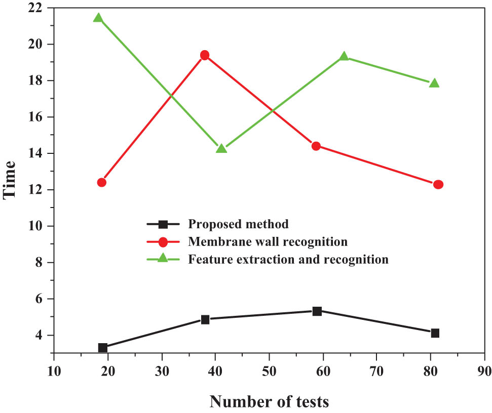
Weld seam identification time of photoelectric sensor in three methods.
According to Figure 5, the time consumed by the author’s method for automatic identification of photoelectric sensor welds is within 6 s, and the time consumed by film wall identification method for automatic identification of photoelectric sensor welds is within 20 s, and the time consumed by feature extraction and recognition method for automatic recognition of photoelectric sensor weld seam is within 22 s; the time consumed by the author’s method for automatic recognition of photoelectric sensor weld seam is the shortest and the recognition efficiency is the highest [21,22]. In traditional machine vision, vision sensors generally only collect and analyze two-dimensional images, cannot conduct multi-scale analysis of target objects, and are affected by environmental factors such as lighting, which limits their application. Aiming at the shortcomings of traditional machine vision, this article introduces nonlinear features and deep neural networks on the basis of traditional machine vision to realize multi-scale analysis and recognition of target objects. In order to extract the feature information of the target object effectively, the original image is filtered by Gaussian filter, and the edge information of the image is obtained by edge detection. Then the histogram statistical method is used to analyze the edge information. On this basis, nonlinear features are used for multi-scale analysis and identification.
5 Conclusion
Through side test, it is found that the current photoelectric sensor weld automatic recognition technology has problems of low recognition rate and recall rate, and high recognition complexity and long recognition time; for this reason, an automatic recognition method of photoelectric sensor weld seam based on machine vision is proposed. This method first collects the photoelectric sensor weld seam image through machine vision technology; then the Gaussian model is used to extract the target area, and the processed image is input into the quantum gate network recognition model to complete the recognition, which reduces the recognition complexity and improves the recognition rate, F1 value, and recognition efficiency. The author’s method has the highest value among the three test indicators, with the highest accuracy rate of 97%, the highest recall rate of 98%, and the highest F1 value of 94. The time consumed by the author’s method for automatic identification of photoelectric sensor welding is within 6 s, the time spent on the film wall recognition method for automatic identification of photoelectric sensor welding is within 20 s, the time spent by the feature extraction and identification method for automatic identification of photoelectric sensor weld is within 22 s.This article mainly focuses on welding seam visual recognition, welding pose control, and visual system calibration and develops corresponding functional modules through a mixed programming method of VC and MATLAB. However, various obstacles that may exist during the welding process are not considered. In the future, obstacle avoidance technology based on machine vision can be studied, and the development of visual obstacle avoidance function can be completed in the same way as this article. In this article, a target recognition and detection system based on the fusion of vision sensor and deep neural network is designed. The system mainly consists of two parts: target detection based on vision sensor and target recognition based on deep neural network. The object detection and recognition method proposed in this article can be applied to dynamic changes and complex scenes in various complex backgrounds and has a good application prospect. The system proposed in this article has some limitations, such as the algorithm in the calculation accuracy, real-time, and other aspects that have room for improvement. In addition, in the process of target recognition, due to the problems existing in the algorithm itself, the accurate recognition of the target needs further research.
-
Funding information: This study did not receive any funding in any form.
-
Author contributions: Each author made significant individual contributions to this manuscript. Hongbin Jia: writing and performing surgeries; Fanwen Yang: data analysis and performing surgeries; Tao Li and Dr. R. Suresh Kumar: article review and intellectual concept of the article.
-
Conflict of interest: The authors declare that they have no competing interests.
-
Data availability statement: The data used to support the findings of this study are available from the corresponding author upon request.
References
[1] Cheng YC, Wang QY, Jiao WH, Xiao J, Chen SJ, Zhang YM. Automated recognition of weld pool characteristics from active vision sensing. Weld J. 2021;100(5):183S–92S.10.29391/2021.100.015Search in Google Scholar
[2] Fan XA, Gao X, Liu G, Ma N, Zhang Y. Research and prospect of welding monitoring technology based on machine vision. Int J Adv Manuf Technol. 2021;115:3365–91.10.1007/s00170-021-07398-4Search in Google Scholar
[3] Chen S, Teng X, Sang X, Zhang H, Zhuang J. Automatic recognition of welding seam defects in tofd images based on tensorflow. Autom Control Comput Sci. 2022;56(1):58–66.10.3103/S0146411622010035Search in Google Scholar
[4] Wang Z, Li L, Chen H, Wu X, Dong Y, Tian J, et al. Penetration recognition based on machine learning in arc welding: a review. Int J Adv Manuf Technol. 2023;125:3899–923.10.1007/s00170-023-11035-7Search in Google Scholar
[5] Tyystjärvi T, Virkkunen I, Fridolf P, Rosell A, Barsoum Z. Automated defect detection in digital radiography of aerospace welds using deep learning. Weld World. 2022;66(4):643–71.10.1007/s40194-022-01257-wSearch in Google Scholar
[6] Kumar S, Gaur V, Wu C. Machine learning for intelligent welding and manufacturing systems: research progress and perspective review. Int J Adv Manuf Technol. 2022;123:3737–65.10.1007/s00170-022-10403-zSearch in Google Scholar
[7] Zhou B, Pychynski T, Reischl M, Kharlamov E, Mikut R. Machine learning with domain knowledge for predictive quality monitoring in resistance spot welding. J Intell Manuf. 2022;33(4):1139–63.10.1007/s10845-021-01892-ySearch in Google Scholar
[8] Mishra A, Pathak T. Estimation of grain size distribution of friction stir welded joint by using machine learning approach. ADCAIJ: Adv Distrib Comput Artif Intell J. 2021;10(1):99–110.10.14201/ADCAIJ202110199110Search in Google Scholar
[9] Han SC, Park HM, Uhm SH, Choi DY, Jeong HC, Kim YJ, et al. Evaluation of liquid metal embrittlement crack in resistance spot welds under intensive welding condition using industrial X-ray computed tomography and machine learning. Weld World. 2021;65:1887–97.10.1007/s40194-021-01109-zSearch in Google Scholar
[10] Chen G, Sheng B, Luo R, Jia P. A parallel strategy for predicting the quality of welded joints in automotive bodies based on machine learning. J Manuf Syst. 2022;62:636–49.10.1016/j.jmsy.2022.01.011Search in Google Scholar
[11] Xiao M, Yang B, Wang S, Chang Y, Li S, Yi G. Research on recognition methods of spot-welding surface appearances based on transfer learning and a lightweight high-precision convolutional neural network. J Intell Manuf. 2023;34:2153–70.10.1007/s10845-022-01909-0Search in Google Scholar
[12] Miao R, Jiang Z, Zhou Q, Wu Y, Gao Y, Zhang J, et al. Online inspection of narrow overlap weld quality using two-stage convolution neural network image recognition. Mach Vis Appl. 2021;32:27.10.1007/s00138-020-01158-2Search in Google Scholar
[13] Yemelyanova MG, Smailova SS, Baklanova OE. Detection of surface defects in welded joints during visual inspections using machine vision methods. Comput Opt. 2023;47(1):112–7.10.18287/2412-6179-CO-1137Search in Google Scholar
[14] Asif K, Zhang L, Derrible S, Indacochea JE, Ozevin D, Ziebart B. Machine learning model to predict welding quality using air-coupled acoustic emission and weld inputs. J Intell Manuf. 2022;33:881–95.10.1007/s10845-020-01667-xSearch in Google Scholar
[15] Tran TA, Lobov A, Kaasa TH, Bjelland M, Midling OT. CAD integrated automatic recognition of weld paths. Int J Adv Manuf Technol. 2021;115(7-8):2145–59.10.1007/s00170-021-07186-0Search in Google Scholar
[16] Zhang Z, Liu W, Sun X. Image recognition of limited and imbalanced samples based on transfer learning methods for defects in welds. Proc Inst Mech Eng B: J Eng Manuf. 2022;236(12):1643–52.10.1177/09544054221082779Search in Google Scholar
[17] Bologna F, Tannous M, Romano D, Stefanini C. Automatic welding imperfections detection in a smart factory via 2-D laser scanner. J Manuf Process. 2022;73:948–60.10.1016/j.jmapro.2021.10.046Search in Google Scholar
[18] Yu R, Kershaw J, Wang P, Zhang Y. Real-time recognition of arc weld pool using image segmentation network. J Manuf Process. 2021;72:159–67.10.1016/j.jmapro.2021.10.019Search in Google Scholar
[19] Miao R, Shan Z, Zhou Q, Wu Y, Ge L, Zhang J, et al. Real-time defect identification of narrow overlap welds and application based on convolutional neural networks. J Manuf Syst. 2022;62:800–10.10.1016/j.jmsy.2021.01.012Search in Google Scholar
[20] Kumaresan S, Aultrin KJ, Kumar SS, Anand MD. Transfer learning with CNN for classification of weld defect. IEEE Access. 2021;9:95097–108.10.1109/ACCESS.2021.3093487Search in Google Scholar
[21] Baek D, Moon HS, Park SH. In-process prediction of weld penetration depth using machine learning-based molten pool extraction technique in tungsten arc welding. J Intell Manuf. 2022.10.1007/s10845-022-02013-zSearch in Google Scholar
[22] Gantala T, Balasubramaniam K. Automated defect recognition for welds using simulation assisted TFM imaging with artificial intelligence. J Nondestr Eval. 2021;40:28.10.1007/s10921-021-00761-1Search in Google Scholar
© 2023 the author(s), published by De Gruyter
This work is licensed under the Creative Commons Attribution 4.0 International License.
Articles in the same Issue
- Research Articles
- The regularization of spectral methods for hyperbolic Volterra integrodifferential equations with fractional power elliptic operator
- Analytical and numerical study for the generalized q-deformed sinh-Gordon equation
- Dynamics and attitude control of space-based synthetic aperture radar
- A new optimal multistep optimal homotopy asymptotic method to solve nonlinear system of two biological species
- Dynamical aspects of transient electro-osmotic flow of Burgers' fluid with zeta potential in cylindrical tube
- Self-optimization examination system based on improved particle swarm optimization
- Overlapping grid SQLM for third-grade modified nanofluid flow deformed by porous stretchable/shrinkable Riga plate
- Research on indoor localization algorithm based on time unsynchronization
- Performance evaluation and optimization of fixture adapter for oil drilling top drives
- Nonlinear adaptive sliding mode control with application to quadcopters
- Numerical simulation of Burgers’ equations via quartic HB-spline DQM
- Bond performance between recycled concrete and steel bar after high temperature
- Deformable Laplace transform and its applications
- A comparative study for the numerical approximation of 1D and 2D hyperbolic telegraph equations with UAT and UAH tension B-spline DQM
- Numerical approximations of CNLS equations via UAH tension B-spline DQM
- Nonlinear numerical simulation of bond performance between recycled concrete and corroded steel bars
- An iterative approach using Sawi transform for fractional telegraph equation in diversified dimensions
- Investigation of magnetized convection for second-grade nanofluids via Prabhakar differentiation
- Influence of the blade size on the dynamic characteristic damage identification of wind turbine blades
- Cilia and electroosmosis induced double diffusive transport of hybrid nanofluids through microchannel and entropy analysis
- Semi-analytical approximation of time-fractional telegraph equation via natural transform in Caputo derivative
- Analytical solutions of fractional couple stress fluid flow for an engineering problem
- Simulations of fractional time-derivative against proportional time-delay for solving and investigating the generalized perturbed-KdV equation
- Pricing weather derivatives in an uncertain environment
- Variational principles for a double Rayleigh beam system undergoing vibrations and connected by a nonlinear Winkler–Pasternak elastic layer
- Novel soliton structures of truncated M-fractional (4+1)-dim Fokas wave model
- Safety decision analysis of collapse accident based on “accident tree–analytic hierarchy process”
- Derivation of septic B-spline function in n-dimensional to solve n-dimensional partial differential equations
- Development of a gray box system identification model to estimate the parameters affecting traffic accidents
- Homotopy analysis method for discrete quasi-reversibility mollification method of nonhomogeneous backward heat conduction problem
- New kink-periodic and convex–concave-periodic solutions to the modified regularized long wave equation by means of modified rational trigonometric–hyperbolic functions
- Explicit Chebyshev Petrov–Galerkin scheme for time-fractional fourth-order uniform Euler–Bernoulli pinned–pinned beam equation
- NASA DART mission: A preliminary mathematical dynamical model and its nonlinear circuit emulation
- Nonlinear dynamic responses of ballasted railway tracks using concrete sleepers incorporated with reinforced fibres and pre-treated crumb rubber
- Two-component excitation governance of giant wave clusters with the partially nonlocal nonlinearity
- Bifurcation analysis and control of the valve-controlled hydraulic cylinder system
- Engineering fault intelligent monitoring system based on Internet of Things and GIS
- Traveling wave solutions of the generalized scale-invariant analog of the KdV equation by tanh–coth method
- Electric vehicle wireless charging system for the foreign object detection with the inducted coil with magnetic field variation
- Dynamical structures of wave front to the fractional generalized equal width-Burgers model via two analytic schemes: Effects of parameters and fractionality
- Theoretical and numerical analysis of nonlinear Boussinesq equation under fractal fractional derivative
- Research on the artificial control method of the gas nuclei spectrum in the small-scale experimental pool under atmospheric pressure
- Mathematical analysis of the transmission dynamics of viral infection with effective control policies via fractional derivative
- On duality principles and related convex dual formulations suitable for local and global non-convex variational optimization
- Study on the breaking characteristics of glass-like brittle materials
- The construction and development of economic education model in universities based on the spatial Durbin model
- Homoclinic breather, periodic wave, lump solution, and M-shaped rational solutions for cold bosonic atoms in a zig-zag optical lattice
- Fractional insights into Zika virus transmission: Exploring preventive measures from a dynamical perspective
- Rapid Communication
- Influence of joint flexibility on buckling analysis of free–free beams
- Special Issue: Recent trends and emergence of technology in nonlinear engineering and its applications - Part II
- Research on optimization of crane fault predictive control system based on data mining
- Nonlinear computer image scene and target information extraction based on big data technology
- Nonlinear analysis and processing of software development data under Internet of things monitoring system
- Nonlinear remote monitoring system of manipulator based on network communication technology
- Nonlinear bridge deflection monitoring and prediction system based on network communication
- Cross-modal multi-label image classification modeling and recognition based on nonlinear
- Application of nonlinear clustering optimization algorithm in web data mining of cloud computing
- Optimization of information acquisition security of broadband carrier communication based on linear equation
- A review of tiger conservation studies using nonlinear trajectory: A telemetry data approach
- Multiwireless sensors for electrical measurement based on nonlinear improved data fusion algorithm
- Realization of optimization design of electromechanical integration PLC program system based on 3D model
- Research on nonlinear tracking and evaluation of sports 3D vision action
- Analysis of bridge vibration response for identification of bridge damage using BP neural network
- Numerical analysis of vibration response of elastic tube bundle of heat exchanger based on fluid structure coupling analysis
- Establishment of nonlinear network security situational awareness model based on random forest under the background of big data
- Research and implementation of non-linear management and monitoring system for classified information network
- Study of time-fractional delayed differential equations via new integral transform-based variation iteration technique
- Exhaustive study on post effect processing of 3D image based on nonlinear digital watermarking algorithm
- A versatile dynamic noise control framework based on computer simulation and modeling
- A novel hybrid ensemble convolutional neural network for face recognition by optimizing hyperparameters
- Numerical analysis of uneven settlement of highway subgrade based on nonlinear algorithm
- Experimental design and data analysis and optimization of mechanical condition diagnosis for transformer sets
- Special Issue: Reliable and Robust Fuzzy Logic Control System for Industry 4.0
- Framework for identifying network attacks through packet inspection using machine learning
- Convolutional neural network for UAV image processing and navigation in tree plantations based on deep learning
- Analysis of multimedia technology and mobile learning in English teaching in colleges and universities
- A deep learning-based mathematical modeling strategy for classifying musical genres in musical industry
- An effective framework to improve the managerial activities in global software development
- Simulation of three-dimensional temperature field in high-frequency welding based on nonlinear finite element method
- Multi-objective optimization model of transmission error of nonlinear dynamic load of double helical gears
- Fault diagnosis of electrical equipment based on virtual simulation technology
- Application of fractional-order nonlinear equations in coordinated control of multi-agent systems
- Research on railroad locomotive driving safety assistance technology based on electromechanical coupling analysis
- Risk assessment of computer network information using a proposed approach: Fuzzy hierarchical reasoning model based on scientific inversion parallel programming
- Special Issue: Dynamic Engineering and Control Methods for the Nonlinear Systems - Part I
- The application of iterative hard threshold algorithm based on nonlinear optimal compression sensing and electronic information technology in the field of automatic control
- Equilibrium stability of dynamic duopoly Cournot game under heterogeneous strategies, asymmetric information, and one-way R&D spillovers
- Mathematical prediction model construction of network packet loss rate and nonlinear mapping user experience under the Internet of Things
- Target recognition and detection system based on sensor and nonlinear machine vision fusion
- Risk analysis of bridge ship collision based on AIS data model and nonlinear finite element
- Video face target detection and tracking algorithm based on nonlinear sequence Monte Carlo filtering technique
- Adaptive fuzzy extended state observer for a class of nonlinear systems with output constraint