Influence of processing parameters on slab stickers during continuous casting
-
Yu Liu
 ,
Yuanpeng Tian
,
Yuanpeng Tian

Abstract
In this study, the parameters of 44 sticker breakout samples were analysed. The research mainly focused on the steel grades and slab thickness of stickers. Other processing parameters, such as slab width, casting speed, mould fluctuation, heat flux and operation, were also discussed. The results show that the number of stickers of low carbon steel and low alloy steel was 16 and 28, respectively. The stickers of low carbon steel were less than those of low alloy steel regardless of the thickness and width. The ratio of stickers per 1,000 casting heats of 220, 260 and 320 mm thickness slabs was 2.5, 0.5 and 0.6, respectively. The higher casting speed of 220 mm thickness slabs made the casting status unsteady and caused more stickers. From the perspective of width, the stickers were gradually increased along with the increase in width due to the worse mould slag. This study provides a foundation to reduce slab stickers and is helpful for a more efficient technology of continuous casting.
1 Introduction
Breakout is a serious accident during continuous casting. The liquid steel overflowed from the slab shell not only decreases the quality of the slab product but also destroys the second cooling equipment and stops the productive process [1,2,3]. A sticker between mould and slab shell is the main cause of breakout, which accounts for 70% to 80%. In recent years, the problem caused by slab sticker breakout is more obvious along with the casting speed increase and development of effective continuous casting technology, which hinders the further increase in casting speed and decreases slab quality [4].
In order to avoid breakout, some metallurgical researchers carried out many meaningful studies. On one hand, some breakout prediction systems (BOPSs) were developed to detect the sticker breakout [5,6,7], such as mould thermocouple monitoring, thermal image monitoring [8,9], heat flux monitoring and friction monitoring [10]. Although BOPS could prevent breakout by reducing casting speed, this operation also decreased the slab quality due to the decrease in casting speed. If the causes of sticker breakout could be found before its formation, the stickers would be eliminated at the beginning. Therefore, some influence parameters, such as pouring temperature, mould slag, casting speed, mould fluctuation and heat flux, were investigated [11,12,13,14,15]. However, steel grades, slab thickness and operation have not been studied, which are the important influence parameters to sticker breakout.
This research was based on the data of wide and thick slab casters from 2015 to 2017. A total of 44 sticker breakout samples were confirmed. The main casting parameters of sticker breakout were investigated, such as steel grade, slab thickness, slab width, casting speed and mould fluctuation. The research results can provide a foundation to prevent sticker breakout.
2 Experiment
The radius of the arc continuous caster was 10.75 m, whose metallurgical length was 28.8 m. The mould length was 0.9 m and the standard mould level was 0.8 m. The slab thicknesses were 0.22, 0.26 and 0.32 m and the width was 1.8–2.7 m. The maximum and minimum casting speeds were 1.2 and 0.75 m/min. The main parameters are shown in Table 1.
Arc continuous caster parameters
| Item | Parameters |
|---|---|
| Strand | 1 |
| Slab width | 1.8–2.7 m |
| Slab thickness | 0.22, 0.26, 0.32 m |
| Radius | 10.75 m |
| Metallurgical length | 28.8 m |
| Mould length | 0.9 m |
| Mould level | 0.8 ± 0.003 m |
| Drive | Hydraulic drive |
| Oscillation frequency | 40–400 times/min |
| Casting speed | 0.75–1.2 m/min |
3 Influence of processing parameters
3.1 Steel grade
From 2015 to 2017, more than 10,000 slabs were casted with about 50 steel grades. The 44 stickers were mainly of the Q235, Q345 and Q420 steel grades, which could be divided to two main types: carbon steel and low alloy steel.
Figure 1 shows stickers of different steel grades with the same thickness. There were ten stickers in 0.22 m thickness slab, which contained six stickers of low carbon steel and four stickers of low alloy steel. The casted 0.26 m thickness slabs had the most stickers, which of low carbon steel and low alloy steel were 9 and 20, respectively. The 0.32 m thickness slabs contained only one sticker of carbon steel and four stickers of low alloy steel. Although low carbon steel stickers of 220 mm slabs were more than those of low alloy steel, it can be seen that the total stickers of low alloy steel are more than those of low carbon steel.
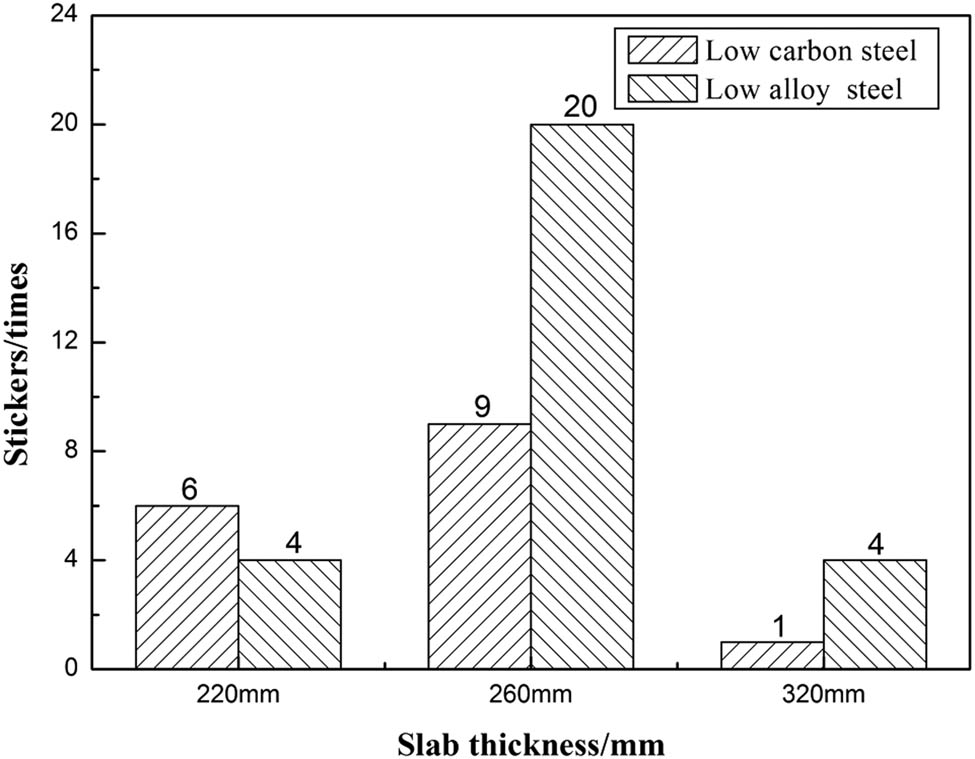
Stickers of different steel grades with the same thickness.
Figure 2 depicts stickers of different steel grades with the same width. The stickers of low carbon steel with width 2,080, 2,580 and 2,780 mm were 5, 5 and 3, respectively, whereas the stickers of low alloy steel with width 2,080, 2,580 and 2,780 mm were 10, 11 and 17. It is noticeable that the stickers of low alloy steel are more than those of low carbon steel about two times.

Stickers of different steel grades with the same width.
From the above data, it can be concluded that stickers of low alloy steel were more than those of low carbon steel regardless of the same thickness or width. On one hand, low alloy steel had more alloy elements, such as Mn and Si, which were used to reduce the amount of O and S elements. This also made the shrinkage of the slab shell become larger and non-uniform. Then, the thin slab tended to have a microdeformation due to liquid steel pressure [16]. When the deformation was big enough, the slab shell would be stuck to the mould copper plate. On the other hand, the addition of rare earth elements was a routine process of low alloy steel production. Although it improved the quality of slab, it also produced some oxides or inclusions with high melting point. Those were easily to be captured by mould liquid slag, which increased the viscosity and melting point. Then, liquid slag would be harder to flow into the gap between mould and slab shell, which made the lubrication worse and sticker occur [17,18]. Therefore, the sticker between mould and slab easily formed when low alloy steel was casted.
3.2 Slab thickness
All 44 sticker samples were from 220, 260 and 320 mm thick slabs, which were 10, 29 and 5, respectively. Figure 3 represents the casting heat and sticker percentage with different slab thicknesses. The casting heats of 260 mm thickness slab were more than those of 220 mm thickness slab about 71.6%, and the increase in sticker percentage was about 43.3%. The stickers increased along with the casting heat increase. While 320 mm slabs were casted, the percentage of casting heats and stickers both decrease. Table 2 shows stickers per 1,000 casting heats of different slab thicknesses. It can be seen that 220 mm thickness slab had 2.5 stickers per 1,000 casting heats, which was higher obviously than those of 260 and 320 mm thickness slabs. Therefore, the continuous casting process of 260 and 320 mm slabs was more stable and the sticker’s probability was smaller. The reason was that the 220 mm slab usually had a higher casting speed, which required a larger amount consumption of mould slag. Then, the thickness of liquid slag became more nonuniform along with the increase in casting speed, which made sticker breakout occur more easily. Therefore, the 220 mm thickness slabs should be paid more attention about the casting speed and mould powder.
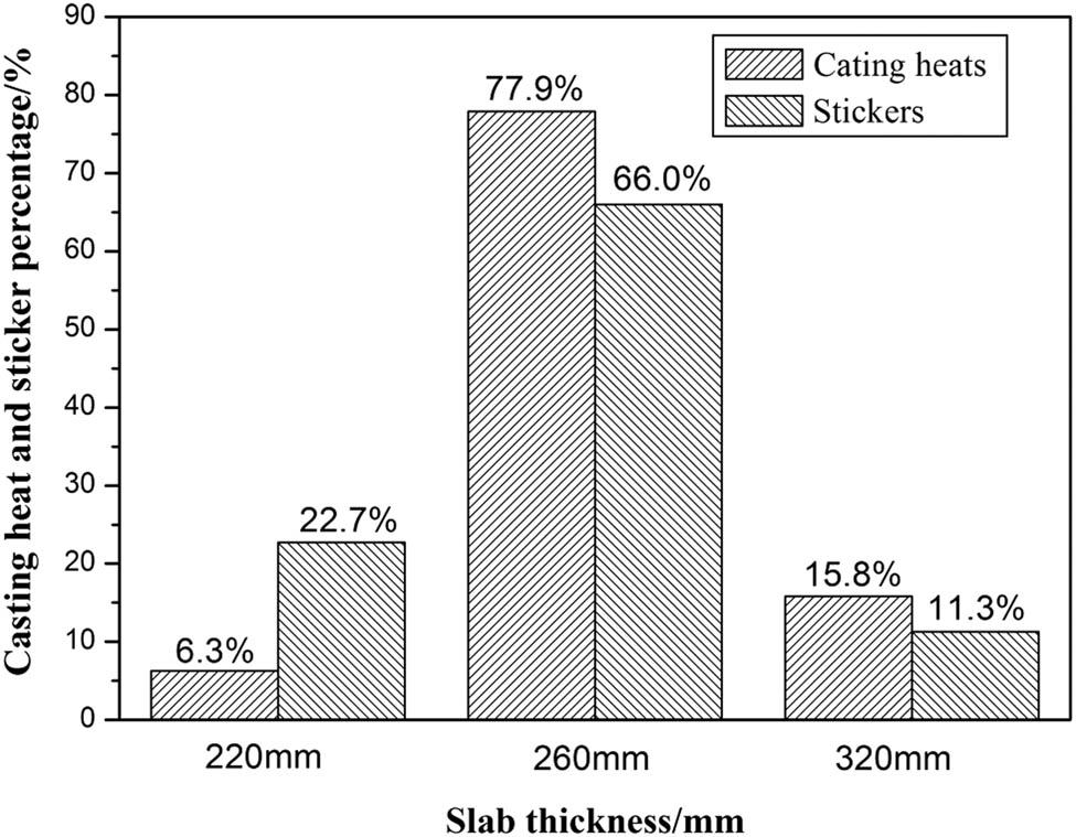
Casting heat and sticker percentage with different slab thicknesses.
Stickers per 1,000 casting heats of different slab thicknesses
| Slab thickness | 220 mm | 260 mm | 320 mm |
|---|---|---|---|
| Stickers per 1,000 | 2.5 | 0.6 | 0.5 |
3.3 Slab width
As 260 mm thick slab had the most stickers, casting heat and sticker breakout percentage of different width were calculated. In Figure 4, the casting heat percentages of 2,080 and 2,580 mm were 59% and 26.1%, which showed a decreased trend. But the sticker breakout percentage of 2,580 mm was 6.9% higher than that of 2,080 mm. The 2,780 mm thick slab had the lowest percentage of sticker breakout, since the casting heat percentage was only 14.9%. The stickers per 1,000 casting heats of 2,080, 2,580 and 2,780 mm were 0.4, 1.1 and 1.2, respectively, which obviously increased along with the increase in slab width. With the increase in slab width, the meltdown and inflow of the mould liquid slag probably became uneven and the larger dimension may have less slag consumption for strand shell. It is one of the main reasons for the slab sticker. On the other hand, the wider slab had a larger sticking area. Under the shrinkage force and ferrostatic pressure acting on the wide face, the comprehensive force may push the strand shell to contact with the mould copper plate, which produced a sticker breakout directly. Therefore, while the wider and thicker slabs are casted, the slag meltdown, inflow of mould slag and operation of pushing slag should be given appropriate attention.
3.4 Casting speed
Figure 5 shows sticker breakout of different slab dimensions along with casting speed increase. There was one sticker when the 260 × 2,580 mm slabs were produced at the casting speed 0.6 and 0.7 m/min. The increase in casting speed did not bring the increase in stickers. However, there were ten stickers while the casting speed was 0.75 m/min. Therefore, 0.6 and 0.7 m/min were the steady casting speeds and the casting speed 0.7 m/min was preferable due to the higher production efficiency. In the same way, the 260 × 2,080 mm slabs were more suitable for production at 0.8 m/min. The stickers of 220 mm thick slabs increased along with the increase in casting speed first, and it decreased when 220 mm thick slabs were casted at 1.25 m/min. According to the casting records, 1.25 m/min was not the normal casting speed and the slabs were not produced at this speed very much. Overall, the 320 and 220 mm thick slabs had a similar trend and the steady casting speeds were 0.6 and 0.8 m/min, respectively. Although the high casting speed can enhance the productive effectiveness of continuous casting, it also needs more consumption of mould slag, cooling water and liquid steel, which makes the process of continuous casting more complicated. Once the mould lacks the liquid slag, the sticker occurs. From this point, the 220 mm thick slabs have more stickers per 1,000 casting heats as shown in Table 2. Therefore, to avoid sticker breakout and obtain a continuous production, the slabs produced at higher casting speed need more attention.

Casting heat and sticker breakout percentage of 260 mm thick slab.
3.5 Mould level fluctuation
In steady state casting, the mould level is required to be constant and its fluctuation is controlled at less than 3 mm. However, the mould level usually has fluctuation due to the difference in steel grades. Figure 6 represents the mould level fluctuation of stickers with different steel grades. There was only one sticker with the mould level fluctuation less than 3 mm, and another sticker’s mould level fluctuation was 3–5 mm. The total 26 stickers of mould level fluctuation 5–10 mm included 15 low alloy steel grades and 11 low carbon steel grades. The total nine stickers of mould level fluctuation 10–20 mm included five low alloy steel grades and four low carbon steel grades. The whole six stickers of mould level fluctuation more than 20 mm were all casted with low alloy steel grades. It can be concluded that the mould level fluctuation of low alloy steel is more than that of low carbon steel, which is another reason that the stickers of low alloy steel are more than those of low carbon steel. The reason is that the strand shell of low alloy steel is more uneven than that of low carbon steel, which is likely to produce the bulging. While the rollers of second cooling section press the strand shell, the mould level will be a larger up and down. The thin strand shell around meniscus is easily broken and stuck to the mould copper plate, such as a sticker of 220 × 2,580 mm occurred on 22 July 2015, which was caused by a large mould level fluctuation of 28 mm. On the other hand, the low alloy steel is easy to have submerged entry nozzle (SEN) clogging, which disturbs the flowing of liquid steel and produce a large mould level fluctuation. The liquid slag was broken by the large mould level fluctuation, and a sticker occurred. Therefore, the mould level should be controlled strictly to avoid sticker breakout, especially producing low alloy steel.

Sticker breakout of different slab dimensions along with casting speed increase.
3.6 Sticker position
Of the 44 sticker samples, 43 cases occurred on the wide faces. Figure 7 shows the sticker positions on the inside and outside radius of slabs with different slab widths. Of 43 cases, 29 stickers occurred on the centre zone. Of these, of 5 cases in 320 mm thickness slabs, 4 stickers occurred on the centre zone, accounting for 80%; of 28 cases in 260 mm thickness slabs, 19 stickers occurred on the centre zone, accounting for 67.9%; and of 10 cases in 220 mm thickness slabs, 6 stickers occurred on the centre zone, accounting for 60%. It can be concluded that the stickers tend to take place on the centre zone more, and this probability grows up along with the increase in slab width.

Mould level fluctuation of stickers with different steel grades.
On one hand, the strand shell of the centre zone is thinner than that of mould corner and narrow face, as these have two dimensions heat transfer. Under the liquid steel pressure, the thinner shell is closer to the mould copper plate, which makes liquid slag inflow harder to the gap. So the centre zone has more stickers than those of other two zones. On the other hand, along with the increase in slab width, the contractility of the mould edge and narrow faces makes the strand shell of wide faces be stretched largely. Under this tensile force, the strand shell with a larger thickness is closer to mould copper plates more. Meanwhile, the tensile force makes the thinner strand shell broken easily.
3.7 Cooling water temperature
Table 3 shows the stickers and root mean square (RMS) of cooling water temperature of different seasons. The Q3 and Q4 have the maximum 19 stickers and the minimum 7 stickers. The cooling water temperature of Q3 is higher than other three seasons and the temperature ranges from 28.8 to 36.8°C, as shown in Figure 8. The temperature fluctuation of cooling water is very obvious. Table 3 also represents the RMS of cooling water temperature. The Q3 has the highest RMS value of 2.62, and Q4 has the least RMS value of 0.4. The reason is that the environment temperature of Q3 is very high in this steel plant, and the consistent temperature of cooling water is not easily controlled. The change in cooling water makes the uniformity of strand shell worse, and the thinner strand shell is close or stuck to the mould copper plate. Therefore, while slabs are casted at the Q3, the temperature cooling water and its fluctuation should be given more attention.
Stickers and RMS of cooling water temperature of different seasons
| Item | Q1 | Q2 | Q3 | Q4 |
|---|---|---|---|---|
| Stickers | 8 | 10 | 19 | 7 |
| RMS | 2.25 | 1.4 | 2.62 | 0.4 |

Sticker positions on (a) inside and (b) outside radius of slabs with different slab widths.
3.8 Operation
As shown in Table 4, the stickers of operation groups A, B, C and D are 9, 11, 13 and 10, respectively. The group C has the most stickers. The number of stickers of four groups is close, so it means that they have the similar level of operation. But 20 stickers occurred within 1 h around the shift time (8:00, 16:00 and 24:00), as shown in Figure 9. The ignorance of mould power supply and the difference in pushing mould powder operation are the main problems of shift change. Once the local strand shell is in the lack of mould power, the sticker will occur at this position. So the fore and after operation groups should keep the mould power enough and do the same operation of pushing mould power during shift change.
Stickers of different operation groups
| Group | A | B | C | D |
|---|---|---|---|---|
| Stickers | 9 | 11 | 13 | 10 |
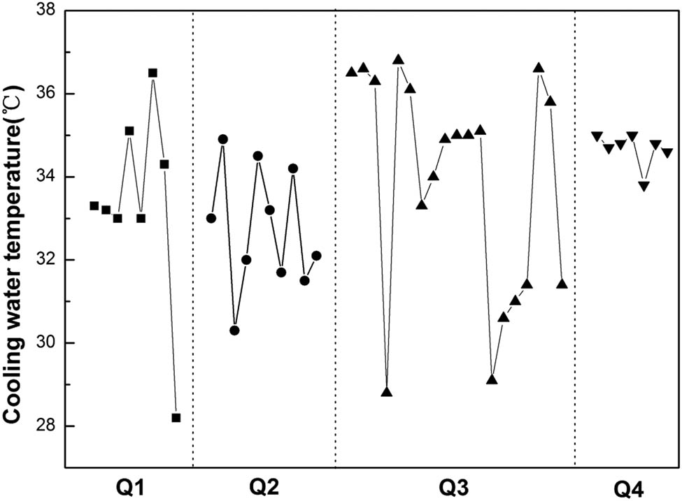
Cooling water temperature of four seasons.
4 Heat flux
4.1 Heat flux of wide copper plates
Figure 10 depicts the average and difference of heat flux of wide copper plates. From Figure 10a, the heat fluxes increase with the increase in casting speed. The 2,080 mm wide slabs casted at the speed 0.9 m/min had the most stickers, and the heat fluxes range from 1.07 to 1.21 MW/m2. The value of heat flux fluctuation is 0.14 MW/m2. The values of heat flux fluctuation of 2,580 and 2,780 mm slabs are 0.21 and 0.25 MW/m2 at casting speeds 0.7 and 0.75 m/min. It can be seen that the wider slab has a large fluctuation of heat flux. From Figure 10b, the difference in heat flux of 2,780 mm range from −0.12 to 0.06 MW/m2, which is larger than those of the 2,580 and 2,080 mm slabs. Along with increase in slab width, the average and difference of heat flux increase obviously, which increases the difference in shell thickness and thermal stress. The sticker or other defects take place at the thinner position easily [20]. Therefore, while the wider slabs are casted, the consistent heat fluxes are helpful to avoid stickers and decrease surface defects.

Sticker time out of a total of 24 h.
4.2 Heat flux fluctuation
Figure 11 depicts heat flux of mould copper plates compared with that of steady state. It can be seen that the 90.91% heat fluxes are less than 5%. It demonstrates that the heat flux is rather steady in most cases before stickers. The reason is that the local heat flux caused by sticker is less compared with the heat flux of the whole copper plate, therefore, the fluctuation of heat flux is not obvious. So, heat flux is not sensitive enough for use as one of the criteria in a BOPS.

The average (a) and difference (b) of heat flux of wide copper plates.
4.3 Heat flux of narrow face
In the actual production, the heat flux of the narrow face is supposed to be lower than that of the wide face, which is about 70–90% of that of the wide face [19]. In Figure 12, only two stickers occurred in this range. In most cases, the percentages are over 90%, and the highest is 122%. It can be concluded that the high heat flux of the narrow face is another reason of stickers. In practice, the cooling water of the narrow face should be controlled in an appropriate volume.
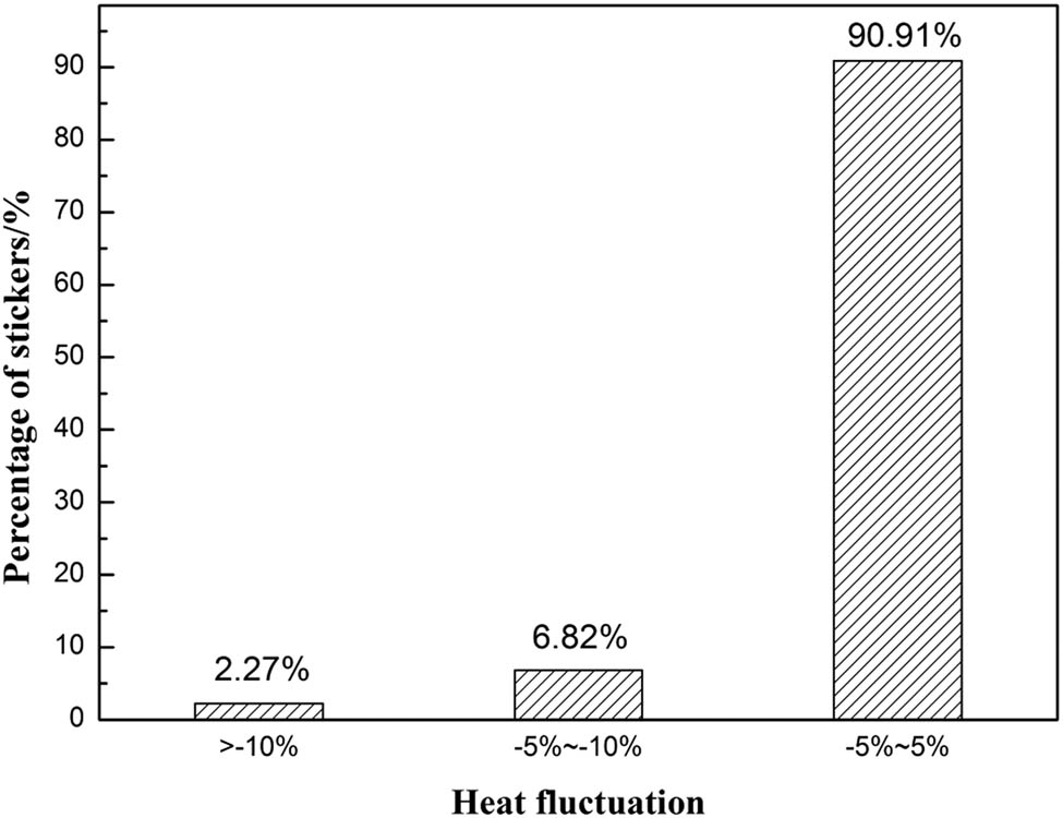
Heat flux of mould copper plates compared with that of steady state.
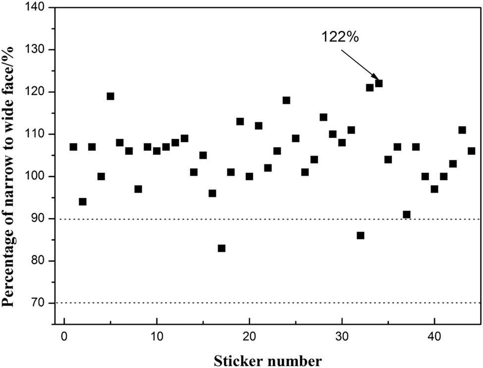
Percentage of heat flux of narrow face to wide face.
5 Conclusion
The stickers of low alloy steel were more than those of low carbon steel regardless of the thickness and width due to the added Mn, Si and rare earth elements, which made the strand shell non-uniform and changed the viscosity and melting point mould slag. Meanwhile, the mould level fluctuation of low alloy steel was usually larger than that of low carbon steel, which increased the risk of slab stickers. Therefore, the slabs of low alloy steel should be given more attention on mould slag and strand uniformity.
From the perspective of width, the stickers increased with the increase in slab width due to the more consumption of mould slag when 260 mm thick slabs were casted. However, from the perspective of thickness, the 220 mm thickness slab had the largest ratio of 2.5 stickers per 1,000 casting heats. The reason is that 220 mm slabs were always produced at higher casting speed and casting status was more unstable than that of other thickness slabs. Therefore, while the slabs are casted at higher casting speed or larger width, the worse status of mould slag should be given more attention.
The 90.9% stickers have less than 5% fluctuation of the heat flux, which shows that the heat flux fluctuation is not sensitive enough for use as one of the criteria in a BOPS. But the fluctuation of heat flux usually increases with the increase in slab width. Therefore, while the wider slabs are casted, the heat fluxes should be consistent and have less fluctuation.
The maximum steady casting speeds of 260 × 2,080 mm and 260 × 2,580 mm slabs are 0.7 and 0.8 m/min. Meanwhile, the stickers are influenced by operation and cooling water temperature.
Acknowledgments
The authors would like to acknowledge financial support from the National Natural Science Foundation of China (51974056/51704073/51474047), Science and Technology Development of Jilin Province (20180520065JH), “13th Five-Year Plan” Science and Technology Research Project of Jilin Provincial Education Department (JJKH20180419KJ/JJKH20180427KJ) and Technology Innovation Development Project of Jilin City (20166013). This project was also financially supported by the Key Laboratory of Solidification Control and Digital Preparation Technology (Liaoning Province).
References
[1] Lee, D., C.-H. Moon, S.-C. Moon, and H.-D. Park. Development of healing control technology for reducing breakout in thin slab casters. Control Engineering Practice, Vol. 17, 2009, pp. 3–13.10.1016/j.conengprac.2008.04.012Search in Google Scholar
[2] Schaak P., R. Kalter, C. Hol, R.-C. Schimmel, S. Meijer, and E. Zor. Reduction of start-of-cast breakouts at the Direct Sheet Plant at TaTa Steel in Ijmuiden. METEC and 4th ESTAD, 2019, pp. 1–8.Search in Google Scholar
[3] Meng, Q., B. Li, J. Qi, and C. Yao. Using GA-BP neural network for sticking breakout prediction in continuous slab casting. International Journal of Simulation: Systems, Science and Technology, Vol. 17, No. 36, 2016, pp. 431–435.Search in Google Scholar
[4] Qian, H.-T., F. He, X. Xie, Z.-H. Zhu, L.-Y. Zhang, L.-L. Zhang, et al. Recovery mechanism of the sticking-type breakout during continuous casting of steel. Ironmaking & Steelmaking, Vol. 46, No. 3, 2017, pp. 259–268.10.1080/03019233.2017.1368956Search in Google Scholar
[5] Duan, H.-Y., X.-D. Wang, Y. Bai, M. Yao, and Q.-T. Guo. Integrated approach to density-based spatial clustering of applications with noise and dynamic time warping for breakout prediction in slab continuous casting. Metallurgical and Materials Transactions B, Vol. 50, No. 5, 2019, pp. 2343–2353.10.1007/s11663-019-01633-wSearch in Google Scholar
[6] Ansari, M.-O., J. Ghose, and R. Kumar. Neural network based breakout predicting system for all four strands of caster in a continuous casting shop – a case study. Advances in Intelligent Systems and Computing, Vol. 509, 2017, pp. 89–99.10.1007/978-981-10-2525-9_9Search in Google Scholar
[7] He, F., and L.-Y. Zhang. Mold breakout prediction in slab continuous casting based on combined method of GA-BP neural network and logic rules. International Journal of Advanced Manufacturing Technology, Vol. 95, No. 9–12, 2018, pp. 4081–4089.10.1007/s00170-017-1517-1Search in Google Scholar
[8] Liu, Y, X.-D. Wang, F.-M. Du, M. Yao, Y.-L. Gao, F.-W. Wang, et al. Computer vision detection of mold breakout in slab continuous casting using an optimized neural network. International Journal of Advanced Manufacturing Technology, Vol. 88, No. 1–4, 2017, pp. 557–564.10.1007/s00170-016-8792-0Search in Google Scholar
[9] Liu, Y., X.-D. Wang, F.-M. Du, L.-W. Kong, M. Yao, X.-B. Zhang. Visual detection based on computer vision for sticker breakout in slab continuous casting. Ironmaking & Steelmaking, Vol. 42, 2015, pp. 417–423.10.1179/1743281214Y.0000000244Search in Google Scholar
[10] Ma, Y., B.-H. Fang, Q.-Q. Ding, and F.-Y. Wang, Analysis of mold friction in a continuous casting using wavelet transform. Metallurgical and Materials Transactions B, Vol. 49, No. 2, 2018, pp. 558–568.10.1007/s11663-018-1168-0Search in Google Scholar
[11] Liu, Y., X.-D. Wang, M. Yao, X.-B. Zhang, H. Ma, Z. Wang, et al. Effect of casting parameters on sticker breakout and its propagation behaviour during slab continuous casting. Ironmaking & Steelmaking, Vol. 41, 2014, pp. 748–755.10.1179/1743281214Y.0000000189Search in Google Scholar
[12] Ray, K., and I. Basak. Local heat flux profiles and interfacial thermal resistance in steel continuous casting. Journal of Materials Processing Technology, Vol. 255, 2018, pp. 605–610.10.1016/j.jmatprotec.2018.01.011Search in Google Scholar
[13] Klug, J.-L., D.-R. Silva, S.-L. Freitas, M.-M. Pereira, N.-C. Vilela, and D. Jung. Fluorine-free mould powders for billet casting-technological parameters and industrial tests. Steel Research International, Vol. 83, No. 8, 2012, pp. 791–799.10.1002/srin.201200018Search in Google Scholar
[14] Tang, L., M. Yao, X.-D. Wang, and X.-B. Zhang. Non-uniform thermal behavior and shell growth within mould for wide and thick slab continuous casting. Steel Research International, Vol. 83, No. 12, 2012, pp. 1203–1213.10.1002/srin.201200075Search in Google Scholar
[15] Yu, S., M.-J. Long, D.-F. Chen, H.-S. Fan, H.-S. Yu, H.-M. Duan, et al. Effect of the mold corner structure on the friction behavior in slab continuous casting molds. Journal of Materials Processing Technology, Vol. 270, 2019, pp. 157–167.10.1016/j.jmatprotec.2019.02.009Search in Google Scholar
[16] Lan, P., H.-Y. Tang, and J.-Q. Zhang. Solidification microstructure, segregation, and shrinkage of Fe–Mn–C twinning-induced plasticity steel by simulation and experiment. Metallurgical and Materials Transactions A, Vol. 47, No. 6, 2016, pp. 2964–2984.10.1007/s11661-016-3445-3Search in Google Scholar
[17] Gao, E.-Z., W.-L. Wang, and L. Zhang. Effect of alkaline earth metal oxides on the viscosity and structure of the CaO–Al2O3 based mold flux for casting high-al steels. Journal of Non-Crystalline Solids, Vol. 473, 2017, pp. 79–86.10.1016/j.jnoncrysol.2017.07.029Search in Google Scholar
[18] Liu, J., and C. Liu. Optimization of mold inverse oscillation control parameters in continuous casting process. Materials and Manufacturing Processes, Vol. 30, 2015, pp. 563–568.10.1080/10426914.2015.1004696Search in Google Scholar
[19] Mao, J.-H., and S.-W. Zhang. Causes and counter measures for sticking breakout in wide slab caster. Continuous Casting, Vol. 4, 2007, pp. 22–24.Search in Google Scholar
[20] Yang, J., Z.-Z. Cai, and M.-Y. Zhu. Transient thermo-fluid and solidification behaviors in continuous casting mold: evolution phenomena. ISIJ International, Vol. 58, No. 2, 2018, pp. 299–308.10.2355/isijinternational.ISIJINT-2017-445Search in Google Scholar
© 2020 Yu Liu et al., published by De Gruyter
This work is licensed under the Creative Commons Attribution 4.0 International License.
Articles in the same Issue
- Research Article
- Electrochemical reduction mechanism of several oxides of refractory metals in FClNaKmelts
- Study on the Appropriate Production Parameters of a Gas-injection Blast Furnace
- Microstructure, phase composition and oxidation behavior of porous Ti-Si-Mo intermetallic compounds fabricated by reactive synthesis
- Significant Influence of Welding Heat Input on the Microstructural Characteristics and Mechanical Properties of the Simulated CGHAZ in High Nitrogen V-Alloyed Steel
- Preparation of WC-TiC-Ni3Al-CaF2 functionally graded self-lubricating tool material by microwave sintering and its cutting performance
- Research on Electromagnetic Sensitivity Properties of Sodium Chloride during Microwave Heating
- Effect of deformation temperature on mechanical properties and microstructure of TWIP steel for expansion tube
- Effect of Cooling Rate on Crystallization Behavior of CaO-SiO2-MgO-Cr2O3 Based Slag
- Effects of metallurgical factors on reticular crack formations in Nb-bearing pipeline steel
- Investigation on microstructure and its transformation mechanisms of B2O3-SiO2-Al2O3-CaO brazing flux system
- Energy Conservation and CO2 Abatement Potential of a Gas-injection Blast Furnace
- Experimental validation of the reaction mechanism models of dechlorination and [Zn] reclaiming in the roasting steelmaking zinc-rich dust process
- Effect of substituting fine rutile of the flux with nano TiO2 on the improvement of mass transfer efficiency and the reduction of welding fumes in the stainless steel SMAW electrode
- Microstructure evolution and mechanical properties of Hastelloy X alloy produced by Selective Laser Melting
- Study on the structure activity relationship of the crystal MOF-5 synthesis, thermal stability and N2 adsorption property
- Laser pressure welding of Al-Li alloy 2198: effect of welding parameters on fusion zone characteristics associated with mechanical properties
- Microstructural evolution during high-temperature tensile creep at 1,500°C of a MoSiBTiC alloy
- Effects of different deoxidization methods on high-temperature physical properties of high-strength low-alloy steels
- Solidification pathways and phase equilibria in the Mo–Ti–C ternary system
- Influence of normalizing and tempering temperatures on the creep properties of P92 steel
- Effect of temperature on matrix multicracking evolution of C/SiC fiber-reinforced ceramic-matrix composites
- Improving mechanical properties of ZK60 magnesium alloy by cryogenic treatment before hot extrusion
- Temperature-dependent proportional limit stress of SiC/SiC fiber-reinforced ceramic-matrix composites
- Effect of 2CaO·SiO2 particles addition on dephosphorization behavior
- Influence of processing parameters on slab stickers during continuous casting
- Influence of Al deoxidation on the formation of acicular ferrite in steel containing La
- The effects of β-Si3N4 on the formation and oxidation of β-SiAlON
- Sulphur and vanadium-induced high-temperature corrosion behaviour of different regions of SMAW weldment in ASTM SA 210 GrA1 boiler tube steel
- Structural evidence of complex formation in liquid Pb–Te alloys
- Microstructure evolution of roll core during the preparation of composite roll by electroslag remelting cladding technology
- Improvement of toughness and hardness in BR1500HS steel by ultrafine martensite
- Influence mechanism of pulse frequency on the corrosion resistance of Cu–Zn binary alloy
- An interpretation on the thermodynamic properties of liquid Pb–Te alloys
- Dynamic continuous cooling transformation, microstructure and mechanical properties of medium-carbon carbide-free bainitic steel
- Influence of electrode tip diameter on metallurgical and mechanical aspects of spot welded duplex stainless steel
- Effect of multi-pass deformation on microstructure evolution of spark plasma sintered TC4 titanium alloy
- Corrosion behaviors of 316 stainless steel and Inconel 625 alloy in chloride molten salts for solar energy storage
- Determination of chromium valence state in the CaO–SiO2–FeO–MgO–CrOx system by X-ray photoelectron spectroscopy
- Electric discharge method of synthesis of carbon and metal–carbon nanomaterials
- Effect of high-frequency electromagnetic field on microstructure of mold flux
- Effect of hydrothermal coupling on energy evolution, damage, and microscopic characteristics of sandstone
- Effect of radiative heat loss on thermal diffusivity evaluated using normalized logarithmic method in laser flash technique
- Kinetics of iron removal from quartz under ultrasound-assisted leaching
- Oxidizability characterization of slag system on the thermodynamic model of superalloy desulfurization
- Influence of polyvinyl alcohol–glutaraldehyde on properties of thermal insulation pipe from blast furnace slag fiber
- Evolution of nonmetallic inclusions in pipeline steel during LF and VD refining process
- Development and experimental research of a low-thermal asphalt material for grouting leakage blocking
- A downscaling cold model for solid flow behaviour in a top gas recycling-oxygen blast furnace
- Microstructure evolution of TC4 powder by spark plasma sintering after hot deformation
- The effect of M (M = Ce, Zr, Ce–Zr) on rolling microstructure and mechanical properties of FH40
- Phase evolution and oxidation characteristics of the Nd–Fe–B and Ce–Fe–B magnet scrap powder during the roasting process
- Assessment of impact mechanical behaviors of rock-like materials heated at 1,000°C
- Effects of solution and aging treatment parameters on the microstructure evolution of Ti–10V–2Fe–3Al alloy
- Effect of adding yttrium on precipitation behaviors of inclusions in E690 ultra high strength offshore platform steel
- Dephosphorization of hot metal using rare earth oxide-containing slags
- Kinetic analysis of CO2 gasification of biochar and anthracite based on integral isoconversional nonlinear method
- Optimization of heat treatment of glass-ceramics made from blast furnace slag
- Study on microstructure and mechanical properties of P92 steel after high-temperature long-term aging at 650°C
- Effects of rotational speed on the Al0.3CoCrCu0.3FeNi high-entropy alloy by friction stir welding
- The investigation on the middle period dephosphorization in 70t converter
- Effect of cerium on the initiation of pitting corrosion of 444-type heat-resistant ferritic stainless steel
- Effects of quenching and partitioning (Q&P) technology on microstructure and mechanical properties of VC particulate reinforced wear-resistant alloy
- Study on the erosion of Mo/ZrO2 alloys in glass melting process
- Effect of Nb addition on the solidification structure of Fe–Mn–C–Al twin-induced plasticity steel
- Damage accumulation and lifetime prediction of fiber-reinforced ceramic-matrix composites under thermomechanical fatigue loading
- Morphology evolution and quantitative analysis of β-MoO3 and α-MoO3
- Microstructure of metatitanic acid and its transformation to rutile titanium dioxide
- Numerical simulation of nickel-based alloys’ welding transient stress using various cooling techniques
- The local structure around Ge atoms in Ge-doped magnetite thin films
- Friction stir lap welding thin aluminum alloy sheets
- Review Article
- A review of end-point carbon prediction for BOF steelmaking process