Significant Influence of Welding Heat Input on the Microstructural Characteristics and Mechanical Properties of the Simulated CGHAZ in High Nitrogen V-Alloyed Steel
-
Jing Zhang
 ,
Guoping Luo
,
Guoping Luo

Abstract
The microstructural characteristics and mechanical properties of the simulated coarse grained heat affected zone (CGHAZ) in high N V-alloyed steel have been conducted under different welding heat input, characterized by the cooling time taken from 800°C to 500°C (t8/5). The experimental results show that the microstructure is dominantly composed of lath bainite (LB) and granular bainite (GB) at t8/5 30 s– 90 s. The content of LB decreases with t8/5 increasing, and that of GB increases. When t8/5 further increases to 120 s and 180 s, the microstructure mainly consists of intragranular polygonal ferrite (IPF) and acicular ferrite (IAF). The higher t8/5 leads to the increased content of intragranular ferrite (IGF). Meanwhile, the prior austenite grain size (PAGS) progressively increases from 56 ± 6.0 μm to 148 ± 9.9 μm as t8/5 increases from 30 s to 180 s. Besides, EBSD analysis indicates that the fraction of high angle grain boundaries (HAGBs) is 0.570, 0.427 and 0.624, respectively, corresponding to t8/5 30, 90 and 180 s. Moreover, the impact toughness decreases as t8/5 increases from 30 s to 90 s caused by the increased PAGS and GB content, and then sharply increases with t8/5 exceeding 90 s due to the increased formation of IGF, especially IAF. Furthermore, the high nitrogen content accelerates V(C,N) precipitation, which not only inhibits the coarsening of prior austenite grains, but promotes the formation of IGF, resulting in the increased number of HAGBs and raising impact toughness.
1 Introduction
Architectural construction nowadays tends to be large-scale, high-rise, long-span and more complicated, which is greatly depended on welding process [1, 2, 3, 4]. The high heat input welding not only improves production efficiency but also reduces energy consumption, attracting the increased attention from metallurgists and extensively being employed in several applications. Nevertheless, the balanced combination of high strength and excellent toughness in structural steel would be seriously upset due to welding thermal cycles experiencing rapid heating (up to 100°C/s-300°C/s), high peak temperature (up to 1350°C or higher), short time incubation (1 s-3 s) and cooling to ambient temperature. During this process, the austenite grain of heat affected zone dramatically growing, especially that of CGHAZ (adjacent to the weld fusion line), leads to the formation of brittle and coarse microstructure and eventually causes poor toughness [5, 6]. Obviously, CGHAZ is one of the weakest parts in HAZ.
The impact toughness of CGHAZ in the welds is largely determined by the microstructural characteristics mainly including microstructure type and prior austenite grain size. It is well established that intragranular ferrite, especially acicular ferrite is the desirable microstructure to obtain superior toughness because the interlocked ferrite plates have different crystallographic orientation with the neighboring microstructure resulting in the high angle grain boundaries [7, 8]. The HAGBs could act as strong barriers blocking the propagation of crack or even changing its direction and thus improves the impact toughness [9, 10, 11]. Moreover, the relatively larger PAGS provides more area for the formation of IGF and increases its content. However, previous literatures [6, 12, 13, 14, 15] reported that the large PAGS probably causes the formation of M-A constituents exerting the adverse effect on toughness and the smaller PAGS brings about better toughness of CGHAZ. As the cooling rate during welding heat cycles controlled by the welding heat input (E) or the time taken from 800°C to 500°C (t8/5) greatly affects the PAGS and decomposition of supercooled austenite [16, 17], it’s essential to clarify the effect of weldingheat input on prior austenite grain size and microstructural evolution, as well as the resultant toughness properties.
In addition, although several previous studies have been done on the weldingproperties in Nb, V and Ti single or composite microalloyed steels combined with adding nitrogen to increase the yield strength, the relationship among prior austenite grain size, microstructure type, impact toughness and welding heat input needs further investigation.Moreover, the nitrogen content was commonly controlled to approximately 100 ppm because of the accepted view that free nitrogen atoms and large micron-sized precipitates, especially titanium nitride and/or carbonitride, do harm to the impact toughness [18, 19]. However, the high N V-alloying has been employed to produce structural steel, of which the nitrogen content reaches 190 ppm. The composition design aims to promote the precipitation of vanadium carbonitrides at austenite region which tends to be heterogeneous nucleation sites for the formation of intragranular ferrite due to their lower misfit and consequently facilitates the welds toughness. Besides, the nanoscaled V(C,N) precipitated in matrix, on dis-locations and at grain boundaries during cooling process greatly enhances the welds strength [20, 21]. Notably, the addition of 190 ppm nitrogen in 0.2 wt% V-alloyed steel not only accelerates the V(C,N) precipitation to a large degree avoiding the waste of V microalloy element but also yields the aging effect caused by free nitrogen atoms according to our previous investigation [4, 22].
In the present work, the correlation among welding heat input, microstructural characteristics and mechanical properties, especially the impact toughness of the simulated CGHAZ was systematically investigated in V alloyed steel with addition of 190 ppm nitrogen for the purpose of further understanding the effect of N exerted on CGHAZ.
The results will be meaningful in developing high strengthened and toughened structural steel with lower production cost.
2 Materials and Methods
2.1 Materials
The chemical composition of high N V-alloyed steel is listed in Table 1. The equivalent carbon content (Ceq) and the welding crack susceptibility index (Pcm) were calculated using Eq. 1 and Eq. 2 [18]. The experimental steel was melted in a medium frequency vacuum induction furnace, cast into 39 kg ingots, and then hot forged into bars with a diameter of 20 mm at the temperature range of 950°C-1150°C. Before experiencing the simulated welding cycles, the base metal (BM) was annealed at 900°C for an hour and then furnace cooled to ambient temperature.
Chemical composition of the experimental steel (wt. %).
| Steel | C | Si | Mn | P | S | V | N | Fe | Ceq | Pcm |
|---|---|---|---|---|---|---|---|---|---|---|
| VN | 0.23 | 0.75 | 1.55 | 0.007 | 0.004 | 0.23 | 0.019 | Bal. | 0.66 | 0.36 |
2.2 Welding Simulation Procedure
The simulated welding thermal cycles with different heat input were conducted on a Gleeble-1500D thermal mechanical simulator. The specimens were cut from the annealed steel bars along the longitudinal direction, and then machined to dimensions of 10.5 mm×10.5 mm×65 mm. The welding simulation procedure was determined by using a two-dimensional Rykalin mathematical model to simulate the thermal cycle of 20 mm thick plate, as shown in Figure 1. The specimens were heated to 1350°C at 100°C/s, and then held for 1 s. The t8/5 was chosen as 30, 60, 90, 120 and 180 s to simulate different welding heat input which was equivalent to that in-service welding of 30.5, 43.2, 52.9, 61.1 and 74.8 kJ/cm, respectively, based on their correlation exhibited as Eq. 3 [23].

Welding thermal cycles applied in CGHAZ simulation for different heat input.
where E-simulated welding heat input, J; t8/5-time taken to cool from 800°C to 500°C; l-thermal conductivity was chosen as 0.36 W/(cm·°C); ρ-density was chosen as 7.85 g/cm3; c-specific heat capacity chosen 0.59 J/(g·°C); T0-preheating temperature was chosen as 20°C; and d-steel thickness was chosen as 2.0 cm.
2.3 Microstructural Characterization
Metallographic specimens were cut near the monitoring thermocouple and prepared by standard techniques before being examined via an optical microscope (OM, ZEISS Axio Observer.A1m) and scanning electron microscope (SEM, JEOL JSM-6510). The measurement of average prior austenite grain size were made on micrographs of grain boundary ferrite and calculated using a linear intercept technique. More detailed microstructural examination including the morphology of microconstituents and the nanoscaled precipitated particles were performed on the thin foil and carbon replica samples using a FEI Tecnai G2 F30 transmission electron microscope (TEM). To analyze crystallographic characteristics, the simulated specimens were electrolytically polished for the observation of electron backscattered diffraction (EBSD) using auger electron spectrometer (AES, ULVAC PHI710). EBSD maps were obtained by analyzing the crystallographic information based on TSL OIM Analysis 7 software. The scanning area and step size are 160 μm × 160 μm and 0.25 μm, respectively. Meanwhile, the larger micron-sized precipitates were observed using field emission scanning electron microscope (FESEM, Zeiss Sigma 500) and the composition was determined by energy dispersion spectroscopy (EDS, Bruker).
2.4 Mechanical Properties
The specimens subjected to welding thermal cycles were machined into standard Charpy impact samples with a dimension of 10 mm×10 mm×55 mm and the notch was placed in the center of simulated CGHAZ. The impact tests were conducted on a pendulum impact testing machine (NI750) at room temperature. The fracture surfaces of the specimens were observed by using a JEOL JSM-6510 SEM.
Vickers hardness was measured at ten randomly selected regions on metallographic specimens under a load of 100 g using a THV-1MD type Vickers tester. The average values reflected the variation of microscopic hardness for the experimental steel with different welding heat input.
3 Results and Discussion
3.1 Effect of Welding Heat Input on Microstructural Evolution
The optical and scanning electron micrographs of the experimental steel in the BM and the simulated CGHAZ with different heat input are shown in Figures 2 and 3. The microstructure of BM is composed of polygonal ferrite (PF) and pearlite (P), as shown in Figures 2(a) and 3(a). At t8/5 30 s, the microstructure predominantly consisting of lath bainite and some fine ferrite netting along prior austenite grain boundary (PAGB) is shown in Figures 2(b) and 3(b). Laths with the same orientation got together and formed into packets and blocks while the laths with different orientations divided the prior austenite grain into different regions. From Figures 2(c) and 3(c), the microstructure at t8/5 60 s consists of lath bainite, granular bainite coupled with a small amount of grain boundary ferrite (GBF) and ferrite side plate (FSP) which nucleates and grows from prior austenite grain boundary to the inner grains. As t8/5 increases to 90 s, the volume fraction of GB is obviously increased and some coarse Widmanstatten ferrite (WF) is formed from PAGB, as shown in Figures 2(d) and 3(d). Literatures [6, 24] revealed that the transformation temperature of GB and LB is similar and between the starting temperature of upper bainite and lower bainite while LB forms at a higher cooling rate compared with that of GB, which agrees with the above observed result. When t8/5 further reaches 120 s and 180 s, the size of GBF is markedly increased and simultaneously the untransformed austenite will be gradually enriched with carbon, and thus the pearlite forms surrounding GBF due to local concentrated C. Moreover, the IAF and IPF generated inside of the prior austenite grains are shown in Figures 2(e), 2(f), 3(e) and 3(f), and the volume fraction of IAF and IPF is increased with t8/5 increasing. In general, the simulated CGHAZ corresponding to t8/5 30 s– 90 s has bainitic dominated microstructure composed of LB and GB. The content of GB increases with t8/5 increasing, and that of LB decreases. At t8/5 120 s and 180 s, the simulated CGHAZ is mainly characterized by a mixture of IAF and IPF.

OM micrographs of the BM and the simulated CGHAZ at different t8/5: (a) BM; (b) 30 s; (c) 60 s; (d) 90 s; (e) 120 s; (f) 180 s.
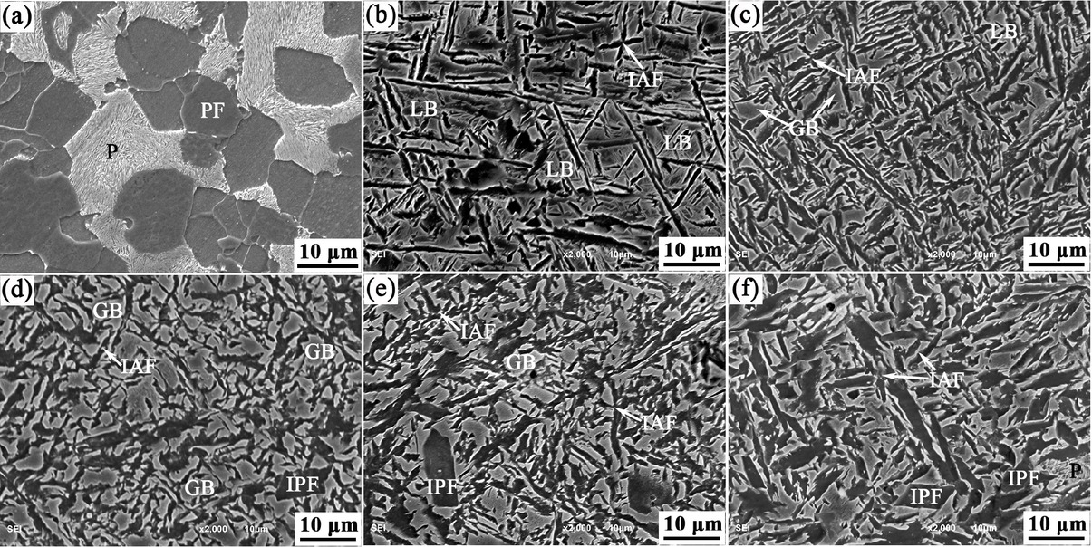
SEM micrographs of the BM and the simulated CGHAZ at different t8/5: (a) BM; (b) 30 s; (c) 60 s; (d) 90 s; (e) 120 s; (f) 180 s.
As stated above, the transformed products of the simulated CGHAZ with different heat input are mostly the intermediate microstructures, including LB, GB, IAF etc., which have the complicated morphology and fine structure. More detailed microstructural features observed by TEM at typical t8/5 for VN can be revealed as shown in Figure 4. The morphology of LB obtained at t8/5 30 s composed of bainitic lath structures with the same orientation is presented in Figure 4(a). For GB obtained at t8/5 90 s, the morphology of ferrite matrix is composed of parallel ferrite plates, as shown in Figure 4(b). Moreover, the M/A island (denoted martensite/austenite constituents) and the rod-like M/A constituents are entrapped among the ferrite plates which are harmful to the impact toughness. The corresponding selected area diffraction pattern (SADP) of zone A is presented in Figure 4(c). In Figures 4(d)-(f), the interlocked nonparallel ferrite plates with high density of dislocations termed as IAF and IPF are obtained at t8/5 180 s, as well as the mixed microstructure of PF and IAF.Mean-while, some pearlite is shown adjacent to large sized ferrite grain. Besides, the precipitates with small size in LB and relatively larger size in IPF and IAF are shown in Figures 4(g)-(i).

TEM thin foil analysis micrographs of microstructure in the simulated CGHAZ: (a) LB at t8/5 30 s; (b) the M/A constituents entrapped among the ferrite laths at t8/5 90 s; (c) the corresponding SADP for M-A island of zone A; (d) PF and IAF at t8/5 180 s; (e) IPF at t8/5 180 s; (f) IAF at t8/5 180 s; (g) precipitates in bainitic plates of (a); (h) precipitates in ferrite grain of (e); (i) precipitates in acicular ferrite plate of (f).
It is well acknowledged that the prior austenite grain size is largely determined to the microstructural evolution and also plays a decisive role in affecting impact toughness. Figure 5 shows the statistical PAGS of the BM and the simulated CGHAZ at different t8/5 for the experimental steel. The PAGS of BM is 46 ± 4.5 μm and it increases from 56 ± 6.0 μmto 148 ± 9.9 μm, as t8/5 extends from 30 s to 180 s. The PAGS is directly related to the dissolution and coarsening of microalloyed carbonitride resulting from the pinning effect of precipitates on austenite growth [23, 25, 26]. According to our previous calculation using Thermo-Calc software coupled with TCFE6 database, the precipitation temperature of V(C,N) is 1210°C [22]. During the welding thermal cycles as shown in Figure 1, the V(C,N) particles were first dissolved in the heating period and subsequently reprecipitated in the cooling process. The obvious coarsening of austenite grain occurred when precipitates are completely dissolved. That is, the PAGS is progressively increased with t8/5 increasing due to the longer dwell time at high temperature.

Prior austenite grain size of the BM and the simulated CGHAZ versus t8/5 (The error bars represent standard deviation).
3.2 Effect of Welding Heat Input on Grain Boundary Misorientation
The crystallographic characteristics of the simulated CG-HAZ that experienced various welding thermal cycles for experimental steel are presented in Figure 6, including the orientation image maps, image quality maps with grain boundary misorientation distribution, and the corresponding misorientation angle distribution histograms. In the image quality maps, high angle grain boundaries are defined as having misorientation greater than 15°, and the low angle grain boundaries (LAGBs) are characterized as boundaries with misorientation between 2° and 15°. It is evident that the distribution of grain boundary misorientation exhibits bimodal characteristic which is primarily distributed in the range of 5°-20° and 40°-65°. Moreover, the fraction of HAGBs is 0.570, 0.427 and 0.624, respectively, corresponding to t8/5 30, 90 and 180 s. At t8/5 30 s, there is a high fraction of HAGBs and a small amount of coarse bainite packet consisted of several blocks with the same orientation. The high angle grain boundary appears just when LB belongs to different Bain Group [27, 28]. At t8/5 90 s, the grain boundary ferrite shows the HAGBs and there is high fraction of LAGBs existed in granular bainite and parallel arranged laths with same orientation. As t8/5 further increases to 180 s, the IAF comprises interlocked structure of ferrite plates, which could divide the prior austenite grain into several regions and the neighboring ferrite plates are mostly high angle misorientation. Besides, IPF also exhibits HAGBs and thus the fraction is obviously increased at t8/5 180 s.

Crystallographic characteristics of the simulated CGHAZ at different t8/5: (a), (d) and (g) 30 s; (b), (e) and (h) 90 s; (c), (f) and (i) 180 s; (a)-(c) orientation image maps; (d)-(f) image quality maps with grain boundary misorientation distribution (LAGBs and HAGBs are indicated by red line and blue line, respectively); and (g)-(i) misorientation angle distribution histograms.
3.3 Effect of Welding Heat Input on Mechanical Properties
Figure 7 shows the Vickers hardness as a function of t8/5 for the simulated CGHAZ and the BM in experimental steel. The hardness of BM is 238 ± 15.0 HV and that of the simulated CGHAZ decreases from 298 ± 14.9 HV to 245 ± 22.3 HV when t8/5 increases from 30 s to 180 s. At t8/5 30 s, the highest hardness is mainly attributed to transformation strengthening from LB, which is undesirable due to the large discrepancy with BM. At t8/5 60 s and 90 s, the hardness decreases due to the formation of GB, FSP and WF, accompanying with decrease of LB. The hardness of the simulated CGHAZ at t8/5 30 s– 90 s are largely higher than that of BM attributed to the bainitic microstructures obtained after welding thermal cycles. At t8/5 120 s and 180 s, the formation of GBF largely decreases the hardness, which offsets the increase due to IAF. In fact, the hardness of base metal and weld metal should be well-matched as a result that the local stress concentration of the welding joints could be released due to the uniform deformation at each sub-region. Therefore, the suitable hardness is acquired at t8/5 180 s and the role of transformation strengthening from acicular ferrite supplemented by nano-scaled V(C,N) precipitation hardening and grain boundaries strengthening make the CGHAZ hardness equivalent to that of BM.

Vickers hardness of the BM and the simulated CGHAZ versus t8/5 (The error bars represent standard deviation).
The total impact energy of the BM and the simulated CGHAZ at different t8/5 is presented in Figure 8. The impact energy of BM is 60 ± 5.5 J, and the value for the simulated CGHAZ is first gradually decreased from 59 ± 6.1 J to 34 ± 2.5 J as t8/5 increases from 30 s to 90 s and then sharply increases to 98 ± 10.8 J with t8/5 increasing to 180 s. The optimal Charpy impact toughness is obtained at t8/5 180 s.

Total impact energy of the BM and the simulated CGHAZ versus t8/5 (The error bars represent standard deviation).
The macrographs and micrographs of the impact fracture in the simulated CGHAZ at typical t8/5 30 s, 90 s and 180 s are shown in Figure 9. The ductile area follows the sequence of (t8/5 = 90 s) < (t8/5 = 30 s) < (t8/5 = 180 s), as shown in Figures 9(a), (d) and (g). In addition, the ductile zone corresponding to t8/5 30 s is composed of large and deep dimples, as well as small and flat dimples, while the brittle zone is represented by small quasi-cleavage facets and some of them concatenate together by tear ridges, as revealed in Figures 9(b) and (c). From Figures 9(e) and (f), the ductile zone for t8/5 90 s consists of flat dimples with different size while the brittle zone is represented by river-patterned large cleavage facets. At t8/5 180 s, the dimples are becoming larger and deeper in Figures 9(h) and (i). Meanwhile, the cleavage facets in brittle zone are very small and connect with dimples and tear ridges. In brief, the fracture morphology is consistent with the data obtained from impact test.
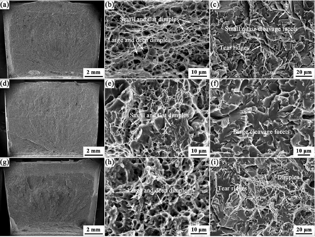
SEM morphologies showing impact fracture surface of the simulated CGHAZ at different t8/5: (a)-(c) 30 s; (d)-(f) 90 s; (g)-(i) 180 s; (a), (d) and (g) macrographs; (b), (e) and (h) micrographs for ductile zone; (c), (f) and (i) micrographs for brittle zone.
3.4 Correlation between the Microstructural Characteristics and Impact Toughness
The impact toughness of the simulated CGHAZ is largely determined by the obtained microstructural characteristics including the prior austenite grain size, microstructure type and high angle grain boundaries.
Figure 10 shows the relationship between the PAGS and the impact toughness of the simulated CGHAZ. It is evident that the total impact energy firstly decreases and then increases with the PAGS increasing. The fine PAGS commonly tends to refine the microconstituents originated from microstructure heredity and consequently improves the impact toughness [6, 15, 29], whereas it is also closely associated with the final microstructure. As the PAGS increases, the number of austenite grains per area decreases resulting in the increased intragranular area, which contributes to the formation of IGF. The transformed microstructure changes from LB+GB to IGF. Moreover, the IGF, especially IAF significantly facilitates the number of HAGBs in contrast with LB and GB. HAGBs obviously hinder the crack propagation or even change its growth direction by acting as strong barriers, remarkably consuming more energy for crack propagation. Additionally, the previous literatures [6, 30, 31] reported that the formation of coarse M/A constituents obviously causes the decrease of impact toughness. In terms of LB, GB and IGF, the optimal microstructure for excellent impact toughness of the simulated CGHAZ is intragranular ferrite, especially IAF.

Total impact energy of the simulated CGHAZ as function of the prior austenite grain size.
The formation of IGF is not only related to the prior austenite grain size but also determined by the nucleation sites. In Figures 11(a) and 12(a), the IPF and IAF nucleate on the precipitated particles with submicron scale in the simulated CGHAZ. As shown in Figures 11(c)-(h), the elements of V and N have the same distribution characterization and the element of C is uniformly distributed in the whole region, which indicates that the nucleus is nitrogen enriched V(C,N) in combination with the EDS spectrum of Point 1 shown in Figure 11(b), as well as that of Point 2 shown in Figure 12(b). The vanadium carbonitride particles could promote the IGF formation due to the lower misfit between the precipitates and ferrite matrix [23]. In addition, an example of precipitate with a diameter of 0.27 μm detected by TEM in carbon replicas extracted from the simulated CGHAZ at t8/5 180s is shown in Figures 13(a) and (b). The ellipsoidal particle is also identified as N enriched V(C,N) from the corresponding EDS and SADP of Point 3 shown in Figures 13(b) and (c).

SEM characterization of the typical IPF and its nucleus in the simulated CGHAZ: (a) SEM image; (b) EDS spectrum; (c) magnification of marked zone in the frame; (d)-(h) EDS mapping analysis of V, N, C, Fe and Mn.

SEM characterization of the typical IAF and its nucleus in the simulated CGHAZ: (a) SEM image; (b) EDS spectrum.

TEM analysis of precipitated particle in the simulated CGHAZ at t8/5 180 s: (a) the low magnification bright field morphology; (b) the high magnification bright field morphology inserted with SAED pattern; (c) EDS spectrum.
4 Conclusions
In the present study, the microstructural characteristics and mechanical properties of the simulated CGHAZ experienced various welding thermal cycles were studied in V-alloyed steel with high nitrogen content of 190 ppm. The main conclusions are as following:
With t8/5 increasing from 30 s to 180 s, the aggravated dissolution and coarsening of precipitates cause the increase of prior austenite grain size,which leads to the microstructure type of the simulated CGHAZ changing from LB+GB to IGF.
The increased content of IAF accounting for a higher fraction of HAGBs is critical to obtain the superior impact toughness in the simulated CGHAZ at t8/5 180 s, of which the formation is attributed to the large PAGS and the N enriched V(C,N) precipitates.
The hardness of the simulated CGHAZ decreases with t8/5 increasing. The suitable hardness is acquired at t8/5 180 s due to the small discrepancy with BM.
Acknowledgement
This work is financially supported by the Natural Science Foundation of China and Inner Mongolia (Grant No. 51804170, 2018BS05002), the scientific research project of higher education in Inner Mongolia autonomous region (Grant No. NJZY18144) and the program for young talents of science and technology in universities of Inner Mongolia autonomous region (Grant No. NJYT-20-B27).
References
[1] Luo, X., Y. W. Niu, X. H. Chen, H. Tang, and Z. D. Wang. High performance in base metal and CGHAZ for ferrite-pearlite steels. Journal of Materials Processing Technology, Vol. 242, 2017, pp. 101–109.10.1016/j.jmatprotec.2016.11.016Search in Google Scholar
[2] Hutchinson, B., J. Komenda, G. S. Rohrer, and H. Beladi. Heat affected zone microstructures and their influence on toughness in two microalloyed HSLA steels. Acta Materialia, Vol. 97, 2015, pp. 380–391.10.1016/j.actamat.2015.05.055Search in Google Scholar
[3] Sugimoto, K., J. Kobayashi, and T. Hojo. Microstructure and Mechanical Properties of Ultrahigh-Strength TRIP-aided Steels. Tetsu To Hagane, Vol. 103, No. 1, 2017, pp. 1–7.10.2355/tetsutohagane.TETSU-2016-064Search in Google Scholar
[4] Zhang, J., W. B. Xin, G. P. Luo, F. M. Wang, and Q. Y. Meng. Effect of the Simulated and Pilot-scaled Thermomechanical Processes on the Microstructure, Precipitates and Mechanical Properties of V–N Alloyed Steel. ISIJ International, Vol. 58, No. 10, 2018, pp. 1883–1892.10.2355/isijinternational.ISIJINT-2018-216Search in Google Scholar
[5] Lan, L. Y., C. L. Qiu, D. W. Zhao, X. H. Gao, and L. X. Du. Microstructural characteristics and toughness of the simulated coarse grained heat affected zone of high strength low carbon bainitic steel. Materials Science and Engineering A, Vol. 529, 2011, pp. 192–200.10.1016/j.msea.2011.09.017Search in Google Scholar
[6] Zhou, P. S., B. Wang, L. Wang, Y. W. Hu, and L. Zhou. Effect of welding heat input on grain boundary evolution and toughness properties in CGHAZ of X90 pipeline steel. Materials Science and Engineering A, Vol. 722, 2018, pp. 112–121.10.1016/j.msea.2018.03.029Search in Google Scholar
[7] Seo, K., H. Ryoo, H. J. Kim, and C. Lee. Quantitative Evaluation of Nucleation Potency of Ti-containing Inclusions for Acicular Ferrite. ISIJ International, Vol. 59, No. 6, 2019, pp. 1105–1112.10.2355/isijinternational.ISIJINT-2018-622Search in Google Scholar
[8] Lu, J. L., Y. P. Wang, Q. M. Wang, H. J. Cheng, and G. G. Cheng. Effect of MnS Inclusions Distribution on Intragranular Ferrite Formation in Medium Carbon Non-Quenched and Tempered Steel for Large-Sized Crankshaft. ISIJ International, Vol. 59, No. 3, 2019, pp. 524–530.10.2355/isijinternational.ISIJINT-2018-509Search in Google Scholar
[9] Xiong, Z. H., S. L. Liu, X. M. Wang, C. J. Shang, X. C. Li, and R. D. K. Misra. The contribution of intragranular acicular ferrite microstructural constituent on impact toughness and impeding crack initiation and propagation in the heat-affected zone (HAZ) of low-carbon steels. Materials Science and Engineering A, Vol. 636, 2015, pp. 117–123.10.1016/j.msea.2015.03.090Search in Google Scholar
[10] Hu, J., L. X. Du, M. Zang, S. J. Yin, Y. G. Wang, X. Y. Qi, X. H. Gao, and R. D. K. Misra. On the determining role of acicular ferrite in V-N microalloyed steel in increasing strength-toughness combination. Materials Characterization, Vol. 118, 2016, pp. 446–453.10.1016/j.matchar.2016.06.027Search in Google Scholar
[11] Shirahata, H., M. Fujioka, and K. Ushioda. Estimation of the Effective Grain Size Controlling Brittle Crack Arrest Toughness of High-strength Steel. Tetsu To Hagane, Vol. 104, No. 3, 2018, pp. 177–185.10.2355/tetsutohagane.TETSU-2017-074Search in Google Scholar
[12] Gu, Y., P. Tian, X. Wang, X. L. Han, B. Liao, and F. R. Xiao. Non-isothermal prior austenite grain growth of a high-Nb X100 pipeline steel during a simulated welding heat cycle process. Materials & Design, Vol. 89, 2016, pp. 589–596.10.1016/j.matdes.2015.09.039Search in Google Scholar
[13] Bonnevie, E., G. Ferrière, A. Ikhlef, D. Kaplan, and J. M. Orain. Morphological aspects of martensite–austenite constituents in intercritical and coarse grain heat affected zones of structural steels. Materials Science and Engineering A, Vol. 385, No. 1-2, 2004, pp. 352–358.10.1016/S0921-5093(04)00859-7Search in Google Scholar
[14] Lambert-Perlade, A., A. F. Gourgues, J. Besson, T. Sturel, and A. Pineau. Mechanisms and modeling of cleavage fracture in simulated heat-affected zone microstructures of a high-strength low alloy steel. Metallurgical and Materials Transactions. A, Physical Metallurgy and Materials Science, Vol. 35, No. 13, 2004, pp. 1039–1053.10.1007/s11661-004-1007-6Search in Google Scholar
[15] Zhu, Z., J. Han, and H. Li. Influence of Heat Input on Microstructure and Toughness Properties in Simulated CGHAZ of X80 Steel Manufactured Using High-Temperature Processing.Metallurgical and Materials Transactions. A, Physical Metallurgy and Materials Science, Vol. 46, No. 11, 2015, pp. 5467–5475.10.1007/s11661-015-3122-ySearch in Google Scholar
[16] Kumar, S., S. K. Nath, and V. Kumar. Continuous cooling transformation behavior in the weld coarse grained heat affected zone and mechanical properties of Nb-microalloyed and HY85 steels. Materials & Design, Vol. 90, 2016, pp. 177–184.10.1016/j.matdes.2015.10.071Search in Google Scholar
[17] Lei, X.W., S. Dong, J. H. Huang, H. Yang, S. H. Chen, and X. K. Zhao. Phase evolution and mechanical properties of coarse-grained heat affected zone of a Cu-free high strength low alloy hull structure steel. Materials Science and Engineering A, Vol. 718, 2018, pp. 437–448.10.1016/j.msea.2018.02.008Search in Google Scholar
[18] Shi, Z. R., C. F. Yang, R. Z. Wang, H. Su, F. Chai, J. F. Chu, and Q. F. Wang. Effect of nitrogen on the microstructures and mechanical properties in simulated CGHAZ of vanadium microalloyed steel varied with different heat inputs. Materials Science and Engineering A, Vol. 649, 2016, pp. 270–281.10.1016/j.msea.2015.09.056Search in Google Scholar
[19] Zhu, Z. X., J. Han, and H. J. Li. Effect of alloy design on improving toughness for X70 steel during welding. Materials & Design, Vol. 88, 2015, pp. 1326–1333.10.1016/j.matdes.2015.09.073Search in Google Scholar
[20] Li, X. L., Z. D.Wang, X. T. Deng, Y. M. Li, H. N. Lou, and G. D.Wang. Precipitation behavior and kinetics in Nb-V-bearing low-carbon steel. Materials Letters, Vol. 182, 2016, pp. 6–9.10.1016/j.matlet.2016.06.072Search in Google Scholar
[21] Zhang, Y. J., K. Shinbo, T. Ohmura, T. Suzuki, K. Tsuzaki, G. Miyamoto, and T. Furuhara. Randomization of Ferrite/austenite Orientation Relationship and Resultant Hardness Increment by Nitrogen Addition in Vanadium-microalloyed Low Carbon Steels Strengthened by Interphase Precipitation. ISIJ International, Vol. 58, No. 3, 2018, pp. 542–550.10.2355/isijinternational.ISIJINT-2017-537Search in Google Scholar
[22] Zhang, J., F. M.Wang, Z. B. Yang, and C. R. Chang. Microstructure, Precipitation, and Mechanical Properties of V-N-Alloyed Steel After Different Cooling Processes. Metallurgical and Materials Transactions. A, Physical Metallurgy and Materials Science, Vol. 47, No. 12, 2016, pp. 6621–6631.10.1007/s11661-016-3763-5Search in Google Scholar
[23] Hu, J., L. X. Du, J. J. Wang, and C. R. Gao. Effect of welding heat input on microstructures and toughness in simulated CGHAZ of V–N high strength steel. Materials Science and Engineering A, Vol. 577, 2013, pp. 161–168.10.1016/j.msea.2013.04.044Search in Google Scholar
[24] Kang, M. K., M. X. Zhang, F. Liu, and M. Zhu. Overall activation energy of isothermal transformation in metal alloy and its mechanism I. Medium temperature (bainite) isothermal transformation in steels. Acta Metallurgica Sinica, Vol. 45, No. 1, 2009, pp. 25–31.Search in Google Scholar
[25] Zhang, L., and T. Kannengiesser. Austenite grain growth and microstructure control in simulated heat affected zones of microalloyed HSLA steel. Materials Science and Engineering A, Vol. 613, 2014, pp. 326–335.10.1016/j.msea.2014.06.106Search in Google Scholar
[26] Moon, J., and S. H. Kim. J. B. Lee and C. H. Lee. Limiting austenite grain size of TiN-containing steel considering the critical particle size. Scripta Materialia, Vol. 56, 2007, pp. 1083–1086.10.1016/j.scriptamat.2007.02.025Search in Google Scholar
[27] Morris, J. W., Jr., C. S. Lee, and Z. Guo. The Nature and Consequences of Coherent Transformations in Steel. ISIJ International, Vol. 43, No. 3, 2003, pp. 410–419.10.2355/isijinternational.43.410Search in Google Scholar
[28] Guo, Z., C. S. Lee, and J. W. Morris, Jr. On coherent transformations in steel. Acta Materialia, Vol. 52, No. 19, 2004, pp. 5511–5518.10.1016/j.actamat.2004.08.011Search in Google Scholar
[29] Zhu, Z. X., J. Han, H. J. Li, and C. Lu. High temperature processed high Nb X80 steel with excellent heat-affected zone toughness. Materials Letters, Vol. 163, 2016, pp. 171–174.10.1016/j.matlet.2015.10.071Search in Google Scholar
[30] Xie, H., L. X. Du, J. Hu, G. S. Sun, H. Y. Wu, and R. D. K. Misra. Effect of thermo-mechanical cycling on the microstructure and toughness in the weld CGHAZ of a novel high strength low carbon steel. Materials Science and Engineering A, Vol. 639, 2015, pp. 482–488.10.1016/j.msea.2015.05.033Search in Google Scholar
[31] Li, C., Y.Wang, and Y. Chen. Influence of peak temperature during in-service welding of API X70 pipeline steels on microstructure and fracture energy of the reheated coarse grain heat-affected zones. Journal of Materials Science, Vol. 46, No. 19, 2011, pp. 6424–6431.10.1007/s10853-011-5592-7Search in Google Scholar
© 2020 J. Zhang et al., published by De Gruyter
This work is licensed under the Creative Commons Attribution 4.0 International License.
Articles in the same Issue
- Research Article
- Electrochemical reduction mechanism of several oxides of refractory metals in FClNaKmelts
- Study on the Appropriate Production Parameters of a Gas-injection Blast Furnace
- Microstructure, phase composition and oxidation behavior of porous Ti-Si-Mo intermetallic compounds fabricated by reactive synthesis
- Significant Influence of Welding Heat Input on the Microstructural Characteristics and Mechanical Properties of the Simulated CGHAZ in High Nitrogen V-Alloyed Steel
- Preparation of WC-TiC-Ni3Al-CaF2 functionally graded self-lubricating tool material by microwave sintering and its cutting performance
- Research on Electromagnetic Sensitivity Properties of Sodium Chloride during Microwave Heating
- Effect of deformation temperature on mechanical properties and microstructure of TWIP steel for expansion tube
- Effect of Cooling Rate on Crystallization Behavior of CaO-SiO2-MgO-Cr2O3 Based Slag
- Effects of metallurgical factors on reticular crack formations in Nb-bearing pipeline steel
- Investigation on microstructure and its transformation mechanisms of B2O3-SiO2-Al2O3-CaO brazing flux system
- Energy Conservation and CO2 Abatement Potential of a Gas-injection Blast Furnace
- Experimental validation of the reaction mechanism models of dechlorination and [Zn] reclaiming in the roasting steelmaking zinc-rich dust process
- Effect of substituting fine rutile of the flux with nano TiO2 on the improvement of mass transfer efficiency and the reduction of welding fumes in the stainless steel SMAW electrode
- Microstructure evolution and mechanical properties of Hastelloy X alloy produced by Selective Laser Melting
- Study on the structure activity relationship of the crystal MOF-5 synthesis, thermal stability and N2 adsorption property
- Laser pressure welding of Al-Li alloy 2198: effect of welding parameters on fusion zone characteristics associated with mechanical properties
- Microstructural evolution during high-temperature tensile creep at 1,500°C of a MoSiBTiC alloy
- Effects of different deoxidization methods on high-temperature physical properties of high-strength low-alloy steels
- Solidification pathways and phase equilibria in the Mo–Ti–C ternary system
- Influence of normalizing and tempering temperatures on the creep properties of P92 steel
- Effect of temperature on matrix multicracking evolution of C/SiC fiber-reinforced ceramic-matrix composites
- Improving mechanical properties of ZK60 magnesium alloy by cryogenic treatment before hot extrusion
- Temperature-dependent proportional limit stress of SiC/SiC fiber-reinforced ceramic-matrix composites
- Effect of 2CaO·SiO2 particles addition on dephosphorization behavior
- Influence of processing parameters on slab stickers during continuous casting
- Influence of Al deoxidation on the formation of acicular ferrite in steel containing La
- The effects of β-Si3N4 on the formation and oxidation of β-SiAlON
- Sulphur and vanadium-induced high-temperature corrosion behaviour of different regions of SMAW weldment in ASTM SA 210 GrA1 boiler tube steel
- Structural evidence of complex formation in liquid Pb–Te alloys
- Microstructure evolution of roll core during the preparation of composite roll by electroslag remelting cladding technology
- Improvement of toughness and hardness in BR1500HS steel by ultrafine martensite
- Influence mechanism of pulse frequency on the corrosion resistance of Cu–Zn binary alloy
- An interpretation on the thermodynamic properties of liquid Pb–Te alloys
- Dynamic continuous cooling transformation, microstructure and mechanical properties of medium-carbon carbide-free bainitic steel
- Influence of electrode tip diameter on metallurgical and mechanical aspects of spot welded duplex stainless steel
- Effect of multi-pass deformation on microstructure evolution of spark plasma sintered TC4 titanium alloy
- Corrosion behaviors of 316 stainless steel and Inconel 625 alloy in chloride molten salts for solar energy storage
- Determination of chromium valence state in the CaO–SiO2–FeO–MgO–CrOx system by X-ray photoelectron spectroscopy
- Electric discharge method of synthesis of carbon and metal–carbon nanomaterials
- Effect of high-frequency electromagnetic field on microstructure of mold flux
- Effect of hydrothermal coupling on energy evolution, damage, and microscopic characteristics of sandstone
- Effect of radiative heat loss on thermal diffusivity evaluated using normalized logarithmic method in laser flash technique
- Kinetics of iron removal from quartz under ultrasound-assisted leaching
- Oxidizability characterization of slag system on the thermodynamic model of superalloy desulfurization
- Influence of polyvinyl alcohol–glutaraldehyde on properties of thermal insulation pipe from blast furnace slag fiber
- Evolution of nonmetallic inclusions in pipeline steel during LF and VD refining process
- Development and experimental research of a low-thermal asphalt material for grouting leakage blocking
- A downscaling cold model for solid flow behaviour in a top gas recycling-oxygen blast furnace
- Microstructure evolution of TC4 powder by spark plasma sintering after hot deformation
- The effect of M (M = Ce, Zr, Ce–Zr) on rolling microstructure and mechanical properties of FH40
- Phase evolution and oxidation characteristics of the Nd–Fe–B and Ce–Fe–B magnet scrap powder during the roasting process
- Assessment of impact mechanical behaviors of rock-like materials heated at 1,000°C
- Effects of solution and aging treatment parameters on the microstructure evolution of Ti–10V–2Fe–3Al alloy
- Effect of adding yttrium on precipitation behaviors of inclusions in E690 ultra high strength offshore platform steel
- Dephosphorization of hot metal using rare earth oxide-containing slags
- Kinetic analysis of CO2 gasification of biochar and anthracite based on integral isoconversional nonlinear method
- Optimization of heat treatment of glass-ceramics made from blast furnace slag
- Study on microstructure and mechanical properties of P92 steel after high-temperature long-term aging at 650°C
- Effects of rotational speed on the Al0.3CoCrCu0.3FeNi high-entropy alloy by friction stir welding
- The investigation on the middle period dephosphorization in 70t converter
- Effect of cerium on the initiation of pitting corrosion of 444-type heat-resistant ferritic stainless steel
- Effects of quenching and partitioning (Q&P) technology on microstructure and mechanical properties of VC particulate reinforced wear-resistant alloy
- Study on the erosion of Mo/ZrO2 alloys in glass melting process
- Effect of Nb addition on the solidification structure of Fe–Mn–C–Al twin-induced plasticity steel
- Damage accumulation and lifetime prediction of fiber-reinforced ceramic-matrix composites under thermomechanical fatigue loading
- Morphology evolution and quantitative analysis of β-MoO3 and α-MoO3
- Microstructure of metatitanic acid and its transformation to rutile titanium dioxide
- Numerical simulation of nickel-based alloys’ welding transient stress using various cooling techniques
- The local structure around Ge atoms in Ge-doped magnetite thin films
- Friction stir lap welding thin aluminum alloy sheets
- Review Article
- A review of end-point carbon prediction for BOF steelmaking process