Limit Support Pressure of Tunnel Face in Multi-Layer Soils Below River Considering Water Pressure
-
 ,
,

Abstract
This paper presents a method to determine the limit support pressure of tunnel face in multi-layer soils below river considering the water pressure. The proposed method is based on the 3D Terzaghi earth pressure theory and the wedge theory considering the water pressure. The limit support pressures are investigated using the limit equilibrium method and compared to those calculated using a numerical method, such as FLAC3D. Four cases focusing different combinations of three layers are analyzed. The results obtained by the numerical method agree well with the predictions of the proposed limit equilibrium method. The limit support pressure obtained using the limit equilibrium method is greater than that obtained by the numerical method. The limit equilibrium method is safe and conservative in obtaining the limit support pressure. The proposed limit equilibrium method is expected to be easily adaptable and to enhance the reliability of tunnel design and construction in multi-layer soils below river.
1 Introduction
With a rapid increase in the construction of subways, shield tunnel technology has been widely used in the construction of tunnels [1, 2, 3]. Tunnel face stability is a key construction consideration in shield tunnel projects. Complex geological conditions can pose serious technical challenges to shield tunnel excavation [4]. The support pressure counteracts the effective earth and water pressure. In order to ensure safety against the collapse of the tunnel face, it is essential to have a reliable analysis of tunnel face stability and predictions of the limit support pressure.
The limit support pressure of the tunnel face is the primary concern in stability analysis [5, 6]. The limit equilibrium method [7], numerical method [8, 9], and experimental method [10] are used to analyze the stability of the tunnel face and support pressure. For the experimental aspects on the stability of the tunnel face, Zhou et al. [11] used the in situ method to analyze the deformation that takes place close to the tunnel face. Messerli et al. [12] investigated the limit support pressure of the tunnel face in sand using experiments. Idinger et al. [13] used centrifuge model tests to investigate face stability on a small scale tunnel in cohesion-less soil, with the slip surface arising from a tunnel invert propagated at an angle of approximately 45∘ + φ/2 to the horizontal. Chambon et al. [14] also studied tunnel face stability using a centrifuge test, and analyzed the effect of tunnel depths on the collapse forms of tunnel faces.
Numerical models are increasingly being used to assess the stability of tunnel faces. Zhang et al. [15] used a 2D numerical approach to study face stability during the slurry shield tunneling process. Chen et al. [16] constructed a 3D discrete element method to analyze the face stability of shallow shield tunnels in dry sand. Zhang et al. [17] adopted 3D numerical simulations to analyze the effects of diameter-to-depth ratios and soil properties on the tunnel face stability. Hasanpour et al. [18] simulated the single shield, double shield, and universal double shield for excavation of deep long tunnels. Graziani et al. [19] considered the creep effects for the Brenner Base Tunnel. Liu et al. [20] conducted a numerical analysis to investigate the influence of different construction schemes on the tunnel heave.
The wedge limit equilibrium model has become very popular in calculating the stability of the tunnel face [21, 22, 23, 24]. Lee et al. [25] revealed the influence of steel pipe-reinforced multi-step grouting on tunnel face stability using the limit equilibrium method. Xu et al. [26] calculated support pressure using the nonlinear Mohr-Coulomb failure criterion. Broere et al. [27] calculated the required limit support pressure using a time-dependent groundwater flow water model and the limit equilibrium wedge model. Leca et al. [28] assumed that the failure zone consisted of a series of conical bodies and derived the limit support pressure. Several researchers [29, 30, 31] derived the limit support pressure for tunnel face failure by assuming that the failure zone is a different shape. Zhang developed a horizontal slice method based on the limit equilibrium analysis theory to analyze tunnel face stability in soft surrounding rocks [32].
When the shield tunnel excavates below the river bed, high water pressure is encountered in the site [33]. Water pressure plays an important role in stability of tunnel excavation, and it may cause the stability of the tunnel face to become difficult to control [34]. If the applied face pressure is less than the limit support pressure, the tunnel face will collapse. The shield tunnel is inevitably constructed below the river, so the research on the stability of the tunnel face in multi-layer soils below river is significant. In this paper, the limit equilibrium method which takes water pressure into account is proposed for the calculation of the limit support pressure, and the solutions are compared with the numerical results for verification. The numerical analysis is carried out using FLAC3D [35].
2 Methods
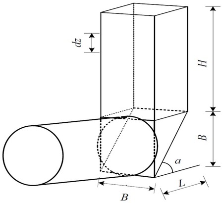
The limit equilibrium method first proposed by Horn [36] is used to analyze the tunnel face stability. The tunnel face is supposed to be three-dimensional failure mode. The simple mechanism model of face stability is illustrated in Figure 1. The tunnel face mechanism approximates the circular face by means of a square and consists of a wedge and a right-angled prism. The wedge is assumed as a rigid body. B,L,H are the width, length, and height of the prism, respectively. The soil is assumed to obey the Mohr-Coulomb failure condition with cohesion represented as c and friction angle represented as φ.
Wedge stability model
The side length B of the square is approximated by setting its area equal to that of the circular tunnel face [36, 37].
where D is the tunnel diameter.
The inclination of wedge α is
The other side length of prism is
Consider an element having a dimension dz within a prism of height H as shown in Figure 1. The upper and lower vertical force of element are, respectively,
where σv is the effective earth pressure from the overlying prism, A is the cross-sectional area of prism.
The vertical friction applied to the lateral side of the element is
where U is the girth of prism, k0 is coefficient of earth pressure at rest, and k0 = 1 − sin φ.
The vertical equilibrium equation of dz reads as follows
where γ is the gravity of the soil.
From the equilibrium equation of the forces acting on the wedge Eq. (7), with boundary conditionsz = 0, σv = p0, p0 is the surcharge on the surface. The effective earth pressure acting upon the wedge can be calculated using the following equation.
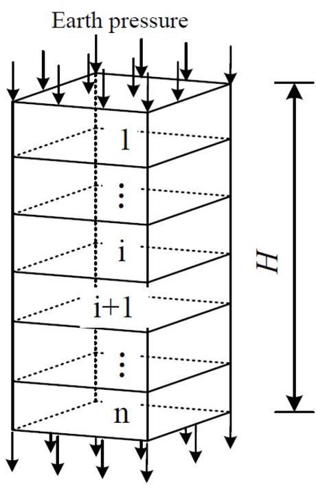
In practical engineering, the overburden layer of a tunnel is often the composite layers. In this paper, the effect of a multi-layered overburden on the overlying earth pressure also can be taken into account. A model of earth pressure calculation is shown in Figure 2.
Model of earth pressure calculation
It is assumed that there are n layers in the composite soils. σv1 and σvi are the earth pressures acting upon the wedge of the first and i-th layer, respectively. They can be respectively expressed as
The earth pressure of the No. n layer can be obtained using a layer to layer method.
Wedge analysis based on the limit equilibrium theory is adopted to obtain the support pressure for the tunnel face stability. Assuming the failure criterion holds along the failure face, a static equilibrium equation can be set up. When a shield tunnel is located below the river, the stability analyses of the shield tunnels face needs to consider the influence of water pressure. Water pressure is usually considered an external force [33], and the forces acting upon the wedge at the face are illustrated in Figure 3. A hydrostatic distribution of water pressures along the slip surface is assumed. There is an effective earth stress σv at the wedge-prism-interface, the self-weight of wedge G, the support force P at the tunnel face, the normal force Non the inclined sliding surface, the shear forces T on the inclined as well as on the sliding surface, the symmetric normal force N' and the shear force T'on the two lateral surfaces of the wedge.
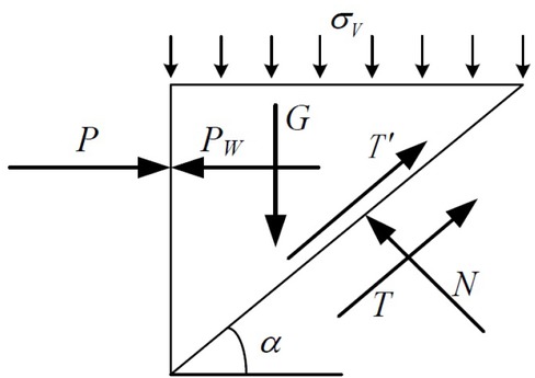
Forces acting upon the wedge
The self-weight of the wedge G
where Bis the height of the wedge.
The vertical mean stress σ'z on the inclined sliding surface
The shear forces T on the inclined sliding surface
The shear force T' on the two sides of the wedge
The vertical earth pressure Pv acting on the top of wedge is presented as
When not taking the infiltration in the excavation face into account, the overburden strata are assumed to be permeable with high permeability, such as sand. Thus, a complete hydraulic connection exists between the river water and the groundwater [38]. The water table can be assumed to be at the surface of the river water for the computation of water pressure acting on the tunnel. In this sense, the water pressure generated by river water can be expressed as
where γw is the unit weight of water, zi is the thickness of the i-th stratum, which is located above the center point of the tunnel face.
According to the limit equilibrium principles, force equilibrium is realized horizontally and vertically. By considering the water pressure and equating force in the vertical and horizontal directions, the equations of equilibrium in the horizontal and vertical dimensions are obtained as
By solving the equilibrium Equations (18) and (19), the limit support force on the tunnel face is calculated as
where
The face stability analysis relevant to a circular rigid tunnel could be idealized. The support pressure is simplified to be uniform [17]. The minimal support pressure termed as the limit support pressure σT can be calculated with consideration of water pressure in river and is given as
3 Results
3.1 Results using the numerical method
The validity of the proposed method is evaluated in this section through a comparison with the numerical model using FLAC3D. The FLAC3D is adopted to predict the limit state and the development of deformation. An explicit Lagrangian calculation scheme is used in the FLAC3D. This is a forward scheme for a nonlinear problem which does not require iteration [18]. This code can deal with the large deformation problem very well and can avoid the problem of numerical instabilities during analysis [39, 40, 41]. Therefore, the FLAC3D is adopted to simulate the limit support pressure. The FLAC3D model is shown in Figure 4. The three-dimensional numerical model is 40 m long, 21 m wide, and 30 m high. A circular tunnel under the three layers soils is considered in evaluating the limit support pressure on the tunnel face. The tunnel support parameters are as follows: the segment is C50 concrete, the segment thickness is 30 cm, the Young modulus of the concrete segment is 34.5 GPa, Poisson’ ratio of the concrete segment is 0.2, and the density is 2.45 g/cm3. The parameters of the tunnel and soils are selected from the case of subway Line No.1 across the Ganjiang River. A circular tunnel with a diameter D of 6 m, a tunnel depth H of 12 m, and a water depth h of 10 m in river is assumed. The analysis is conducted using a linear Mohr-Coulomb yield criterion. Analyses are performed for the four cases, and the mechanical parameters of friction angle φ and cohesion c of the soil stratum are summarized in Table 1. The four cases are used to analyze the situations with the excavation layer as cohesive soil or cohesive soil, and the cases of overlying soil as cohesive soil or cohesive soil. The soil thicknesses of 1-1, 1-2, 1-3 are 6 m, 6 m, 18 m, respectively. For stratum 1-1, 1-2, 1-3, an elastic modulus Eo f 40 MPa, Poisson’ ratio ν of 0.33, and gravity γ of 20 kN/m3 of are selected.
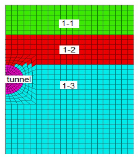
Numerical model of calculation
Mechanical parameters of soil
| soil | Case A | Case B | Case C | Case D | ||||
|---|---|---|---|---|---|---|---|---|
| c /kPa | φ /∘ | c /kPa | φ /∘ | c /kPa | φ /∘ | c /kPa | φ /∘ | |
| 1-1 | 0 | 25 | 5 | 35 | 0 | 25 | 5 | 35 s |
| 1-2 | 5 | 35 | 0 | 25 | 5 | 35 | 0 | 25 |
| 1-3 | 0 | 25 | 0 | 25 | 5 | 35 | 5 | 35 |
The analyses of tunnel face stability and supporting pressure are performed with FLAC3D. The applied support pressure can be normalized by the initial earth pressure [42]. The support pressure ratiois equal to the applied support pressure divided by the initial horizontal earth stress at the center of the tunnel face. The initial support pressure on the face is set as the initial horizontal earth pressure, and is gradually reduced until the tunnel face collapses. The displacements in the surrounding ground have been highlighted. Displacement contoursaround tunnel face and the displacement fields for case A, case B, case C, and case D are plotted in Figure 5. The monitoring displacements in Figure 5 are in the horizontal direction (excavation direction), and the unit of the displacement is in meters. The displacements of the tunnel face are calculated according to the different cases with a variation in soil layers. For case A and case B, the tunnel faces are in cohesionless soils. Case C and case D are in cohesivefrictional soils.
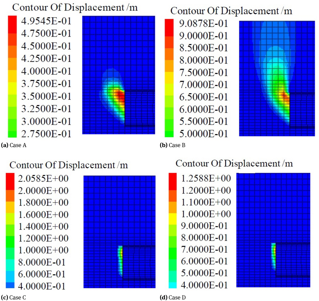
Displacement contours around the tunnel face
The failure zones in case A and case B are obviously larger than that in case C and case D, and mainly concentrate in the upper region of tunnel face. By comparing Figure 5(a) and Figure 5(b), it is evident that the case A has the larger zone of sliding, but is blocked by the cohesive soil layer 1-2 and is mainly concentrate in the soil layer 1-3. The sliding zone in case B extends gradually to the river bed surface, the displacement decreases drastically. For case C and case D, when the tunnel excavates in the cohesive soil layer, the sliding zone shrinks and concentrates in front of the tunnel face. It is obvious that cohesion has an important influence on the failure form.
Tunnel face stability and the behavior of surrounding soils are analyzed with varying support pressure ratios at the tunnel face. Evaluating the relationship between the displacement of a control point (the face center) and the applied support pressure ratio (normalized by initial stress) is a common way to analyze the tunnel face stability [43]. Figure 6(a) and Figure 6(b) show horizontal and vertical displacement of the face center with a variation of support pressure ratios for the case A, case B, case C, and case D, respectively. Large displacement is expected to occur when there is small support pressure ratio. The displacement increases significantly when the support pressure ratio decreases to a certain value. This value is the limit support pressure ratio. From the results of the FLAC3D analysis for the four cases previously mentioned, the calculation results of the limit support pressure on the tunnel face are shown in Table 2.
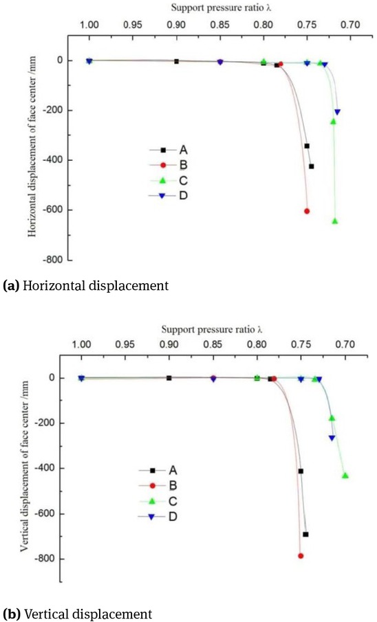
Displacement of the central point of face
Results with the FLAC3D
| Case | Initial earth pressure /kPa | Limit support pressure ratio | Limit support pressure /kPa |
|---|---|---|---|
| A | 275 | 0.755 | 207.63 |
| B | 275 | 0.78 | 214.50 |
| C | 275 | 0.715 | 196.63 |
| D | 275 | 0.720 | 198.00 |
3.2 Results using the limit equilibrium method
Comparative calculations are carried out. The same cases are analyzed using the proposed limit equilibrium method and numerical method using FLAC3D. The analyses of the tunnel face supporting pressure with the proposed limit equilibrium method are preformed. Table 3 compares the limit support pressure obtained using the limit equilibrium method with that obtained from the numerical method.
Results of limit support pressure
| A | B | C | D | |
|---|---|---|---|---|
| numerical method | 207.63 | 214.50 | 196.63 | 198.00 |
| limit equilibrium method | 219.01 | 229.27 | 197.72 | 204.39 |
| error | 5.19% | 6.44% | 0.55% | 3.12% |
4 Discussion
The results of case A and case B, which were excavated in cohesionless soil, are different. The error of them is nearly 10%, although the tunnel excavates at the same soil layer. The reason is that the upper soil layer 1-2 in case A is comprised of cohesive soils, which are conducive to the stability of the tunnel face and prevent the development of a failure zone. Thus, the required limit support pressure to keep the tunnel face stable in case A is small compared to that in case B. When the excavation is in the cohesive soil for case C and case D, their required limit support pressures are similar, although the cover soil layers are different. The limit support pressure in case A and case B are obviously greater than that in case C and case D. The main reason is that the excavation stratum of case A and case B is cohesionless soil.
The limit support pressures calculated by limit equilibrium method are 219.01 kPa, 229.27 kPa, 197.72 kPa, 204.39 kPa for the cases A, B, C, and D, respectively. The results of the limit equilibrium method agree well with numerical calculations with respect to the limit support pressure, as shown in Table 3. The obtained results suggest that the approach proposed herein could be applied for fast estimations of the pressure needed for face support in multilayer soils below river, with consideration to water pressure. These values are about 5%higher than the prediction from the numerical method. Mollon et al. [44] got a similar result for a 2D stability analysis of a pressurized tunnel face in sand. The proposed limit equilibrium method is also an effective method to calculate the limit support pressure on the tunnel face for permeable overburden strata that has a high permeability. It cannot be used for impermeable overburden strata that has a low permeability. The proposed method is suitable for cohesionless soil. The proposed method is reliable and effective when it is used to design the tunnel excavation process.
5 Conclusions
Managing suitable support pressures acting on a tunnel face is very important in stabilizing the tunnel face. In this paper, a limit equilibrium method with considerations for water pressure is proposed to determine the limit support pressure of tunnel faces in multi-layer soils below river. Based on the proposed limit equilibrium methods, the limit support pressures required for tunnel face stability below the river bed are estimated on variable ground. The face stability is also investigated using the FLAC3D. The limit support pressures have been calculated to compare the results of the limit equilibrium method with those from a three-dimension numerical method FLAC3D. There is good agreement between the limit equilibrium results and the numerical results. The limit support pressure using the limit equilibrium method is greater than that obtained by the numerical method. It is safe and efficient when the limit equilibrium method is used to design the support pressure on tunnel face with permeable overburden strata that has a high permeability. This research can provide a theoretical foundation for tunnel engineering practices in multi-layer soils below the river bed. The next stage of the work is studying the limit support pressure for impermeable overburden strata that has a low permeability.
Acknowledgement
The authors gratefully acknowledge the financial support from the National Natural Sciences Foundation of China (Grant: 51468041) and Jiangxi Science Foundation (Grant: 20124ABE02106, 20161BAB203078).
References
[1] Lin C.G., Zhang, Z.M., Wu, S.M., Yu, F., Key techniques and important issues for slurry shield under-passing embankments: a case study of Hangzhou Qiantang River Tunnel. Tunnelling and Underground Space Technology, 2013, 38, 306-32510.1016/j.tust.2013.07.004Search in Google Scholar
[2] Tóth á., Gong Q.M., Zhao J., Case studies of TBM tunneling performance in rock-soil interface mixed ground. Tunnelling and Underground Space Technology, 2013, 38, 140-15010.1016/j.tust.2013.06.001Search in Google Scholar
[3] Kavvadas M.J., Monitoring ground deformation in tunnelling: current practice in transportation tunnels. Engineering Geology, 2005, 79, 93-11310.1016/j.enggeo.2004.10.011Search in Google Scholar
[4] Zhou H., Gao Y., Zhang C.Q., Yang F.J., Hu M.M., Liu H.T., Jiang Y., A 3D model of coupled hydro-mechanical simulation of double shield TBM excavation. Tunnelling and Underground Space Technology, 2018, 71, 1-410.1016/j.tust.2017.07.012Search in Google Scholar
[5] Klar A., Osman A. S., Bolton M., 2D and 3D upper bound solutions for tunnel excavation using ‘elastic’ flow fields. International Journal Numerical Analytical Method in Geomechanics, 2007, 31, 1367-137410.1002/nag.597Search in Google Scholar
[6] Zhao K., Janutolo M., Barla G., A completely 3D model for the simulation of mechanized tunnel excavation. Rock Mechanics and Rock Engineering, 2012, 45, 475-49710.1007/s00603-012-0224-3Search in Google Scholar
[7] Mollon G., Phoon K.K., Dias D., Soubra A.H., A new 2D failure mechanism for face stability analysis of a pressurized tunnel in spatially variable sands. GeoFlorida 2010: Advances in Analysis, Modeling & Design, Florida, 2010, 2052-206110.1061/41095(365)208Search in Google Scholar
[8] Ebadati N., Kaboli M., Modeling stress distribution and the change of ground behavior during excavation of Tehran city underground tunnel, Journal of Geotechnical Geology, 2014, 9, 293-304Search in Google Scholar
[9] Haghi A.H., Asef M.R., Taheri A., Mohkam M., Evaluation of the Heading Confinement Pressure Effect on Ground Settlement for EPBTBM Using Full 3D Numerical Analysis, International Journal of Mining & Geo-Engineering, 2013, 47, 13-32Search in Google Scholar
[10] Takano D., Otani J., Nagatani H., Mukunoki T., Application of X-ray CT boundary value problems in geotechnical engineering-Research on tunnel face failure, Proc. Geocongress, ASCE, Reston, Va, 2006, 1-610.1061/40803(187)50Search in Google Scholar
[11] Zhou H., Qu C.K., Hu D.W., Zhang C. Azhar M.U., Shen Z., Chen J., In situ monitoring of tunnel deformation evolutions from auxiliary tunnel in deep mine. Engineering Geology, 2017, 221, 10-1510.1016/j.enggeo.2017.02.011Search in Google Scholar
[12] Messerli J., Pimentel E., Anagnostou G., Experimental study into tunnel face collapse in sand, ,.Proceedings of the 7th International Conference on Physical Modelling in Geotechnics, Zurich, Switzerland, 2010, 575-580Search in Google Scholar
[13] Idinger G., Aklik P., Wu W. Borja R.I., Centrifuge model test on the face stability of shallow tunnel. Acta Geotechnica, 2011, 6, 105-11710.1007/s11440-011-0139-2Search in Google Scholar
[14] Chambon P., Corté J.F., Shallow tunnels in cohesionless soil stability of tunnel face. Journal of Geotechnical Engineering, 1994, 120, 1148-116510.1061/(ASCE)0733-9410(1994)120:7(1148)Search in Google Scholar
[15] Zhang Z.X., Hu X.Y., Scott K.D., A discrete numerical approach for modeling face stability in slurry shield tunnelling in soft soils. Computers and Geotechnics. 2011, 38, 94-10410.1016/j.compgeo.2010.10.011Search in Google Scholar
[16] Chen R.P., Tang L.J., Ling D.S., Chen Y.M., Face stability analysis of shallow shield tunnels in dry sandy ground using the discrete element method. Computers and Geotechnics, 2011, 38, 187-19510.1016/j.compgeo.2010.11.003Search in Google Scholar
[17] Zhang C.P., Han K.H., Zhang D.L., Face stability analysis of shallow circular tunnels in cohesive–frictional soils. Tunnelling and Underground Space Technology, 2015, 50, 345-35710.1016/j.tust.2015.08.007Search in Google Scholar
[18] Hasanpour R., Advance numerical simulation of tunneling by using a double shield TBM. Computers and Geotechnics, 2014, 57, 37-5210.1016/j.compgeo.2014.01.002Search in Google Scholar
[19] Graziani A., Capata A., Romualdi P., Analysis of rock-TBM-lining interaction in squeezing rock. Felsbau Magazin, 2007, 25, 23-31Search in Google Scholar
[20] Liu H.L., Li P., Liu J.Y., Numerical investigation of underlying tunnel heave during a new tunnel construction. Tunnelling and Underground Space Technology, 2011, 26, 276-28310.1016/j.tust.2010.10.002Search in Google Scholar
[21] Anagnostou G., Kovári K., Face stability conditions with earth pressure balanced shields. Tunnelling and Underground Space Technology, 1996, 11, 165-17310.1016/0886-7798(96)00017-XSearch in Google Scholar
[22] Broere W., On the face support of microtunnelling TBMs. Tunnelling and Underground Space Technology, 2015, 46, 12-1710.1016/j.tust.2014.09.015Search in Google Scholar
[23] Khezri N., Mohamad H., Fatahi B., Stability assessment of tunnel face in a layered soil using upper bound theorem of limit analysis. Geomechanics and Engineering, 2016, 11, 471-49210.12989/gae.2016.11.4.471Search in Google Scholar
[24] Anagnostou G., Kovári K., The face stability of slurry-shield driven tunnels. Tunnelling and Underground Space Technology, 1994, 9, 165-17410.1016/0886-7798(94)90028-0Search in Google Scholar
[25] Lee I.M., Lee J.S., Nam S.W., Effect of seepage force on tunnel face stability reinforced with multi-step pipe grouting. Tunnelling and Underground Space Technology, 2004, 19, 551-56510.1016/j.tust.2004.01.003Search in Google Scholar
[26] Xu J.S., Du D.C., Yang Z.H., Upper bound analysis for deep tunnel face with joined failure mechanism of translation and rotation, Journal of Central South University, 2015, 22, 4310-431710.1007/s11771-015-2979-7Search in Google Scholar
[27] Broere W., van Tol A.F., Time-dependant infiltration and groundwater flowin a face stability analysis. Proceeding of the International Symposium Kyoto 2001: Modern Tunneling Science and Technology, Kyoto, Japan, 2001, 629-63410.1201/9781003077534-5Search in Google Scholar
[28] Leca E., Dormieux L., Upper and lower bound solutions for the face stability of shallow circular tunnels in frictional material. Géotechnique, 1990, 40, 581-60610.1680/geot.1990.40.4.581Search in Google Scholar
[29] Krause, T., Schildvortrieb mit flüssigkeits-und erdgestützter ortsbrust. PhD Thesis, Technical University Carolo-Wilhelmina, 1987Search in Google Scholar
[30] Soubra A.H., Kinematical approach to the face stability analysis of shallow circular tunnels. In: Proc. 8th International Symposium of Plasticity., Canada, British Columbia,2002, 443-445Search in Google Scholar
[31] Mollon G., Dias D., Soubra A.H., Rotational failure mechanisms for the face stability analysis of tunnels driven by pressurized shields. International Journal Numerical Analytical Method in Geomechanics, 2011, 35, 1363-138810.1002/nag.962Search in Google Scholar
[32] Zhang Z.Q., Shi X.Q., Wang B., Li H.Y., Stability of NATM tunnel faces in soft surrounding rocks. Computers and Geotechnics, 2018, 96, 90-10210.1016/j.compgeo.2017.10.009Search in Google Scholar
[33] Min F.L., Zhu W., Lin C., Guo X.J., Opening the excavation chamber of the large-diameter size slurry shield: A case study in Nanjing Yangtze River Tunnel in China. Tunnelling and Underground Space Technology, 2015, 46, 18-2710.1016/j.tust.2014.10.002Search in Google Scholar
[34] Qiu Y., Yang X.A., Xu Q.W., Guo L., Tang Z. H., Li Z., Analysis on stability and instability risk of excavation face of shield tunnel inwater-rich sand layer. China Railway Science, 2015, 36, 55-62.Search in Google Scholar
[35] Itasca Consulting Group Inc, FLAC3D Manual, third ed. (FLAC3D Version 3.1), 2006Search in Google Scholar
[36] Horn N., Horizontaler erddruck auf senkrechte abschlussflächen von tunnelröhren, Landeskonferenz der ungarischen tieffiauindustrie, 1961, 7-16Search in Google Scholar
[37] Bai Y.X., Qi T.Y., Ren G.Q., Xie J.Q., Research on calculation model of limit support pressure on shield face in sandy cobble stratum. Journal of the China Railway Society, 2013, 35(7), 114-122Search in Google Scholar
[38] Lin C.G., Wu S.M., Xia T.D., Design of shield tunnel lining taking fluctuations of river stage into account. Tunnelling and Underground Space Technology, 2015,45, 107-12710.1016/j.tust.2014.09.011Search in Google Scholar
[39] Mollon G., Dias D., Soubra A.H., Probabilistic Analysis of Circular Tunnels in Homogeneous Soil Using Response Surface Methodology. Journal of Geotechnical and Geoenvironmental Engineering, 2009, 135, 1314-132510.1061/(ASCE)GT.1943-5606.0000060Search in Google Scholar
[40] Lin P., Zhou Y.N., Liu H.Y., Wang C., Reinforcement design and stability analysis for large-span tailrace bifurcated tunnels with irregular geometry. Tunnelling and Underground Space Technology, 2013, 38, 189-20410.1016/j.tust.2013.07.011Search in Google Scholar
[41] Diederichs M. S., Mechanistic interpretation and practical application of damage and spalling prediction criteria for deep tunnelling. Canadian Geotechnical Journal, 2007, 44, 1082-111610.1139/T07-033Search in Google Scholar
[42] Huang Z.R., Zhu W., Liang J.H., Qin J.S., A study on the limit support pressure at excavation face of shield tunneling. China Civil Engineering Journal, 2006, 39,112-116.(in Chinese with English abstract)Search in Google Scholar
[43] Vermeer P.A., Ruse N., Marcher T., Tunnel heading stability in drained ground. Felsbau, 2002, 20, 8-18Search in Google Scholar
[44] Mollon G., Phoon K.K., Dias D., Soubra A.H., Validation of a New 2D Failure Mechanism for the Stability Analysis of a Pressurized Tunnel Face in a Spatially Varying Sand. Journal of Engineering Mechanics, 2011, 137, 8-2110.1061/(ASCE)EM.1943-7889.0000196Search in Google Scholar
© 2018 Weiping Liu et al., published by De Gruyter
This work is licensed under the Creative Commons Attribution-NonCommercial-NoDerivatives 4.0 License.
Articles in the same Issue
- Regular Articles
- Spatio-temporal monitoring of vegetation phenology in the dry sub-humid region of Nigeria using time series of AVHRR NDVI and TAMSAT datasets
- Water Quality, Sediment Characteristics and Benthic Status of the Razim-Sinoie Lagoon System, Romania
- Provenance analysis of the Late Triassic Yichuan Basin: constraints from zircon U-Pb geochronology
- Historical Delineation of Landscape Units Using Physical Geographic Characteristics and Land Use/Cover Change
- ‘Hardcastle Hollows’ in loess landforms: Closed depressions in aeolian landscapes – in a geoheritage context
- Geostatistical screening of flood events in the groundwater levels of the diverted inner delta of the Danube River: implications for river bed clogging
- Utilizing Integrated Prediction Error Filter Analysis (INPEFA) to divide base-level cycle of fan-deltas: A case study of the Triassic Baikouquan Formation in Mabei Slope Area, Mahu Depression, Junggar Basin, China
- Architecture and reservoir quality of low-permeable Eocene lacustrine turbidite sandstone from the Dongying Depression, East China
- Flow units classification for geostatisitical three-dimensional modeling of a non-marine sandstone reservoir: A case study from the Paleocene Funing Formation of the Gaoji Oilfield, east China
- Umbrisols at Lower Altitudes, Case Study from Borská lowland (Slovakia)
- Modelling habitats in karst landscape by integrating remote sensing and topography data
- Mineral Constituents and Kaolinite Crystallinity of the <2 μm Fraction of Cretaceous-Paleogene/Neogene Kaolins from Eastern Dahomey and Niger Delta Basins, Nigeria
- Construction of a dynamic arrival time coverage map for emergency medical services
- Characterizing Seismo-stratigraphic and Structural Framework of Late Cretaceous-Recent succession of offshore Indus Pakistan
- Geosite Assessment Using Three Different Methods; a Comparative Study of the Krupaja and the Žagubica Springs – Hydrological Heritage of Serbia
- Use of discriminated nondimensionalization in the search of universal solutions for 2-D rectangular and cylindrical consolidation problems
- Trying to underline geotourist profile of National park visitors: Case study of NP Fruška Gora, Serbia (Typology of potential geotourists at NP Fruška Gora)
- Fluid-rock interaction and dissolution of feldspar in the Upper Triassic Xujiahe tight sandstone, western Sichuan Basin, China
- Calcified microorganisms bloom in Furongian of the North China Platform: Evidence from Microbialitic-Bioherm in Qijiayu Section, Hebei
- Spatial predictive modeling of prehistoric sites in the Bohemian-Moravian Highlands based on graph similarity analysis
- Geotourism starts with accessible information: the Internet as a promotional tool for the georesources of Lower Silesia
- Models for evaluating craters morphology, relation of indentation hardness and uniaxial compressive strength via a flat-end indenter
- Geotourism in an urban space?
- The first loess map and related topics: contributions by twenty significant women loess scholars
- Modeling of stringer deformation and displacement in Ara salt after the end of salt tectonics
- A multi-criteria decision analysis with special reference to loess and archaeological sites in Serbia (Could geosciences and archaeology cohabitate?)
- Speleotourism in Slovenia: balancing between mass tourism and geoheritage protection
- Attractiveness of protected areas for geotourism purposes from the perspective of visitors: the example of Babiogórski National Park (Poland)
- Implementation of Heat Maps in Geographical Information System – Exploratory Study on Traffic Accident Data
- Mapping War Geoheritage: Recognising Geomorphological Traces of War
- Numerical limitations of the attainment of the orientation of geological planes
- Assessment of runoff nitrogen load reduction measures for agricultural catchments
- Awheel Along Europe’s Rivers: Geoarchaeological Trails for Cycling Geotourists
- Simulation of Carbon Isotope Excursion Events at the Permian-Triassic Boundary Based on GEOCARB
- Morphometry of lunette dunes in the Tirari Desert, South Australia
- Multi-spectral and Topographic Fusion for Automated Road Extraction
- Ground-motion prediction equation and site effect characterization for the central area of the Main Syncline, Upper Silesia Coal Basin, Poland
- Dilatancy as a measure of fracturing development in the process of rock damage
- Error-bounded and Number-bounded Approximate Spatial Query for Interactive Visualization
- The Significance of Megalithic Monuments in the Process of Place Identity Creation and in Tourism Development
- Analysis of landslide effects along a road located in the Carpathian flysch
- Lithological mapping of East Tianshan area using integrated data fused by Chinese GF-1 PAN and ASTER multi-spectral data
- Evaluating the CBM reservoirs using NMR logging data
- The trends in the main thalweg path of selected reaches of the Middle Vistula River, and their relationships to the geological structure of river channel zone
- Lithostratigraphic Classification Method Combining Optimal Texture Window Size Selection and Test Sample Purification Using Landsat 8 OLI Data
- Effect of the hydrothermal activity in the Lower Yangtze region on marine shale gas enrichment: A case study of Lower Cambrian and Upper Ordovician-Lower Silurian shales in Jiangye-1 well
- Modified flash flood potential index in order to estimate areas with predisposition to water accumulation
- Quantifying the scales of spatial variation in gravel beds using terrestrial and airborne laser scanning data
- The evaluation of geosites in the territory of National park „Kopaonik“(Serbia)
- Combining multi-proxy palaeoecology with natural and manipulative experiments — XLII International Moor Excursion to Northern Poland
- Dynamic Reclamation Methods for Subsidence Land in the Mining Area with High Underground Water Level
- Loess documentary sites and their potential for geotourism in Lower Silesia (Poland)
- Equipment selection based on two different fuzzy multi criteria decision making methods: Fuzzy TOPSIS and fuzzy VIKOR
- Land deformation associated with exploitation of groundwater in Changzhou City measured by COSMO-SkyMed and Sentinel-1A SAR data
- Gas Desorption of Low-Maturity Lacustrine Shales, Trassic Yanchang Formation, Ordos Basin, China
- Feasibility of applying viscous remanent magnetization (VRM) orientation in the study of palaeowind direction by loess magnetic fabric
- Sensitivity evaluation of Krakowiec clay based on time-dependent behavior
- Effect of limestone and dolomite tailings’ particle size on potentially toxic elements adsorption
- Diagenesis and rock properties of sandstones from the Stormberg Group, Karoo Supergroup in the Eastern Cape Province of South Africa
- Using cluster analysis methods for multivariate mapping of traffic accidents
- Geographic Process Modeling Based on Geographic Ontology
- Soil Disintegration Characteristics of Collapsed Walls and Influencing Factors in Southern China
- Evaluation of aquifer hydraulic characteristics using geoelectrical sounding, pumping and laboratory tests: A case study of Lokoja and Patti Formations, Southern Bida Basin, Nigeria
- Petrography, modal composition and tectonic provenance of some selected sandstones from the Molteno, Elliot and Clarens Formations, Karoo Supergroup, in the Eastern Cape Province, South Africa
- Deformation and Subsidence prediction on Surface of Yuzhou mined-out areas along Middle Route Project of South-to-North Water Diversion, China
- Abnormal open-hole natural gamma ray (GR) log in Baikouquan Formation of Xiazijie Fan-delta, Mahu Depression, Junggar Basin, China
- GIS based approach to analyze soil liquefaction and amplification: A case study in Eskisehir, Turkey
- Analysis of the Factors that Influence Diagenesis in the Terminal Fan Reservoir of Fuyu Oil Layer in the Southern Songliao Basin, Northeast China
- Gravity Structure around Mt. Pandan, Madiun, East Java, Indonesia and Its Relationship to 2016 Seismic Activity
- Simulation of cement raw material deposits using plurigaussian technique
- Application of the nanoindentation technique for the characterization of varved clay
- Verification of compressibility and consolidation parameters of varved clays from Radzymin (Central Poland) based on direct observations of settlements of road embankment
- An enthusiasm for loess: Leonard Horner in Bonn and Liu Tungsheng in Beijing
- Limit Support Pressure of Tunnel Face in Multi-Layer Soils Below River Considering Water Pressure
- Spatial-temporal variability of the fluctuation of water level in Poyang Lake basin, China
- Modeling of IDF curves for stormwater design in Makkah Al Mukarramah region, The Kingdom of Saudi Arabia