Dynamic Reclamation Methods for Subsidence Land in the Mining Area with High Underground Water Level
-
Qiuji Chen
 and
Mengru Hang
and
Mengru Hang

Abstract
Dynamic reclamation for subsidence land is a development trend of ecological restoration in the mining area. It emphasizes that treatments should be taken during or before land damage to control the ecological degradation. Because dynamic reclamation is a complex problem, there still exist many challenges that have to be studied for practical application. In this paper, taking subsidence land in the area with high underground water level as an example, according to the requirements of land use and economic development, key techniques for dynamic reclamation are analyzed based on mine subsidence theories. The research proposes a general mode for dynamic reclamation, and provides a method for calculating the control time of soil excavation, and puts forth an optimization thought for land use, then establishes a procedure for soil reconstruction. The results show that dynamic reclamation can reduce the cost and shorten the land waste time, and enhance the sustainable development ability of the mining area.
1 Introduction
The activities of coal mining have caused massive destruction of farmlands, which has affected the grain production. So, land reclamation has become an urgent task [1, 2, 3]. However, most of methods for land reclamation nowadays just suit for the land that the process of subsidence has been completed, then the damaged land has to be abandoned for a long time of 3-5 years, or even longer [4, 5, 6]. During this period, if no measures were taken to control land degradation, it would not only waste land resources, but also lead to ecological environment deterioration, such as soil erosion, salinization, etc., then increase the difficulty of reclamation in the future. Therefore, dynamic reclamation methods are becoming a hot topic in recent years. It emphasizes that reclamation measures shall be taken during or before the development of subsidence to control the ecological environment degradation [7, 8, 9, 10]. Hu et al. (2013) expounded the necessity and feasibility of concurrent of reclamation and coal mining [3]; Wu et al. (2014) discussed strategy of topsoil stripped method while mining in the high groundwater level area based on GIS [6]; Zhao (2008) presented a general technical model for dynamic reclamation, and studied the reclamation time for high groundwater level in coal mining area [7]. Zhang et al. (2004) considered that the dynamic reclamation was the process that treatment of surface subsidence should be done before the ground was submerged in water based on the result of subsidence prediction [11]. Although many researches have been conducted in recent years, dynamic reclamation is a complex system problem, and different condition needs different methods. Especially, when taking into consideration of construction, there still exist many challenges. The purpose of this study is to 1) obtain the control reclamation time when consideration the construction; 2) optimize the land use structure on the condition of soil balance within subsidence area; 3) achieve the goal of concurrent of reclamation and mining.
2 Study methodology
2.1 Mining conditions setting
Mine subsidence is affected by numerous factors and conditions, such as topography, geography, mining method, and so on, in order to facilitate the analysis, the conditions need to be defined beforehand. In this study, the coal seam is horizontal and it is mined with an even speed. Before subsidence, the terrain is flat and land use is farmland. The region belongs to the area with a high groundwater level. The main goals of dynamic reclamation are to control land degradation, reduce land waste time, and serve as a basis for ecological restoration in the mining area.
2.2 Dynamic predication for mine subsidence
The process of mining subsidence cannot be completed at once. It usually goes through a long period. According to in-situ monitoring data and relevant research results, This process can be explained with the following function [7, 8, 9, 10]:
Where,
Wt is the dynamic subsidence value at time t;
W0 is the maximum of subsidence;
c and k are time influence parameters.
3 Key Points for dynamic reclamation
3.1 Characteristic of land damage in the mining area with high underground water level
In the region with a high groundwater level, after subsidence, most of the surface are accumulated with water, which is the principal feature of the land destruction in this region. Water area can be divided into two parts. One is the perennial water-accumulated zone where the surface elevation after subsidence is lower than the groundwater level, and another is the seasonalwater-accumulated zone where the land became barren due to salinization. The distribution of land damage in subsidence area is illustrated in the Figure 1. There, line J1 is the boundary for mining subsidence area; line J2 is seasonal water-accumulated zone boundary; line J3 is the perennial water-accumulated zone boundary.
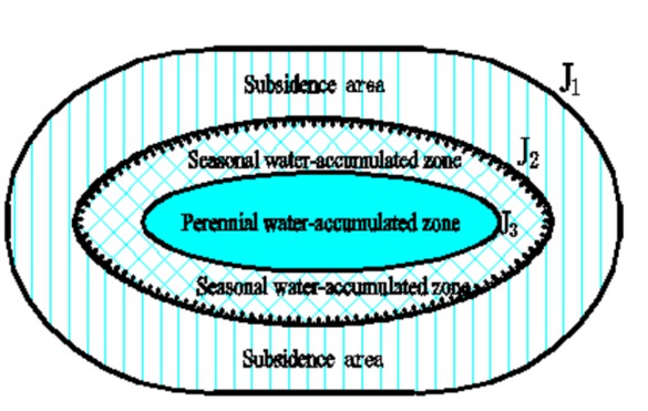
Distribution of land damage in subsidence area with high underground water level.
3.2 Treatment schemes
In order to realize dynamic reclamation, the subsidence area should be firstly divided into three parts along the
direction of work face advance, according to the relation between groundwater level and subsidence. Then they should be further classified into filling areas and digging areas for future treatment (Figure 2).
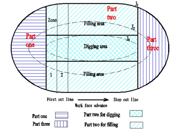
The division in subsidence area for reclamation.
Part one: it is on the side of the first-cut line in subsidence area, belonging to the filling area. The surface of this area is above the groundwater level, and is influenced by seasonal water and salinization. The main treatment measures are to fill the lower place through getting the soil from part two, then ensure the normal farming activities.
Part two: it locates in the middle of the subsidence area, can be separated into filling and digging areas according to the relation between groundwater level and subsidence. Center of this part is filled with water because its surface elevation after subsidence is lower than the groundwater level. The main treatment measures are to further dig the deep areas to fill the shallow areas through zone by zone. Then the deep place after dug can be used as fishpond and the shallow place can be used as cultivated land to plant grain.
Part three: it situates on the side of the stop-cut line, belonging to the filling area. The damage feature of this area is like Part one. The principal treatment measures are also to fill the lower place through getting the soil from part two, then ensure normal farming activities.
In general, the treatment scheme can be summarized as the following three aspects: control reclamation timing along the direction of work face advance; further dig the deep to fill the shallow along perpendicular direction; strip the topsoil and reconstruct new soil profile zone by zone.
3.3 Key points for dynamic reclamation
3.3.1 Determine the control time of soil excavation
It depends on many factors to determine the best time for soil excavation during subsidence process. In this study, the relation between subsidence and groundwater level is used to analyze the control time for the soil excavation, because it has an important influence on the topsoil resources.
Based on the function of dynamic predication for mine subsidence, the relation between time and subsidence can be explained with following formula.
Where,
Wt is the temporary subsidence value at time t;
W0, c and k have the same meaning as before, calculated based on mining condition.
Wt is the key value for soil excavation, and it can be determined by the following requirements according to construction:
Before the surface elevation is lower than the underground water level during the process of subsidence, the topsoil stripping shall be finished.
Avoiding working in water, the thickness of topsoil and the depth for further digging shall be taken into consideration.
These requirements can be explained with following formula.
Where,
Wt is the temporary subsidence value at time t;
H0 is surface elevation before subsidence;
H w is the elevation of underground water level;
d is the thickness of topsoil;
h is the depth of further digging based on the requirement of aquaculture.
3.3.2 Optimize land use structure on the condition of soil balance within subsidence area
In the water-accumulated area, the main treatment is digging the deep to fill the shallow, then the deep area forms ponds for aquaculture and the shallow area becomes farmlands for grain production. The structure of these two types in subsidence area should meet the requirement of soil balance by avoiding damaging more land resources due to occupation or excavation for land reclamation.
Before construction, Part two (Figure 2) can be divided into several zones for land reclamation. One typical zone is selected to design the parameters for the ratio of ponds and farmlands.
Considering the condition that the width of work face in coal seam does not reach critical distance, the subsidence shape of zone is symmetrical along the direction of zone profile, so, half of profile is chosen to design the parameters for reclamation (Figure 3):
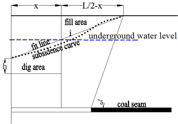
The design for digging the deep to fill the shallow in zone.
In Figure 3h is the depth of further digging based on the requirement of aquaculture. The length of subsidence area in half profile is about L/2. Although the shape of the slope in subsidence area is curved, in order to facilitate the calculation, a line is used to fit the curve of the slope. The gradient i can be calculated based on the depth of subsidence and the length of the zone. Given that the length of further digging along the profile is x, then the length of filling is L/2-x, based on soil balance of digging and filling, the value of x can be calculated with following formula:
It shall be explained that the above parameters are referenced to the value of subsidence in the final stage. During the time of construction, the process of subsidence yet has not been completed, and the subsidence process will continue for some time, which might affect the use of reclamation land. For example, at the time of reclamation, the subsidence stage is like the curve 1 in Figure 4, which will continue to develop after the construction. If the farmland is leveled at this time, the residual subsidence will lead to a slope on the surface of farmland at the end of subsidence, which will affect crop growth and need further treatment. The slope caused by residual subsidence is shown in Figure 4.
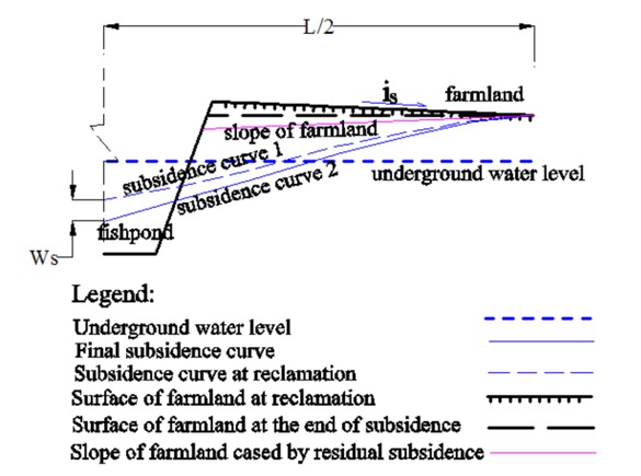
The design of inverse slope for farmland.
So some measures should be considered to minimize the residual deformation. Here, inverse slope is built to compensate for the future subsidence. Its gradient value is calculated based on the following formula:
Where,
is is the gradient of inverse slope in the farmland;
L has the meaning as before.
Ws is residual subsidence value at time t; it can be calculated with the following formula:
Where
Wt is the temporary subsidence value at time of construction;
W0 is the final value of subsidence in the same place.
With the development of subsidence, the inverse slope will gradually decrease, at the end of subsidence, the surface of farmland will become a flat area (Figure 4).
3.3.3 Soil reconstruction procedure based on the process of construction
Soil reconstruction is the core task of land reclamation, and it is the key to determine whether the treatment is successful or not [2, 5]. For dynamic reclamation, its goals must include soil resources protection, in addition to save time and decrease cost of reclamation. Therefore, soil reconstruction is particularly important for dynamic reclamation.
According to the theory of soil science, the soil profile of agricultural soil can be divided into topsoil layer, subsoil layer and bottom layer. Previous land reclamation did not pay much attention to this aspect, resulted in disorder of soil structure and low productivity of land. In order to ensure the soil quality after reclamation, the new soil in reclamation should be reconstructed according to the structure type of the local agricultural soil, and the construction process should be designed reasonably, so as to construct a suitable soil structure. Hu has provided a general model for soil reconstruction [5]. Based on his ideas, the soil reconstruction procedure of dynamic reclamation is proposed in this study. An example of two layers for soil reconstruction is shown in the Figure 5.
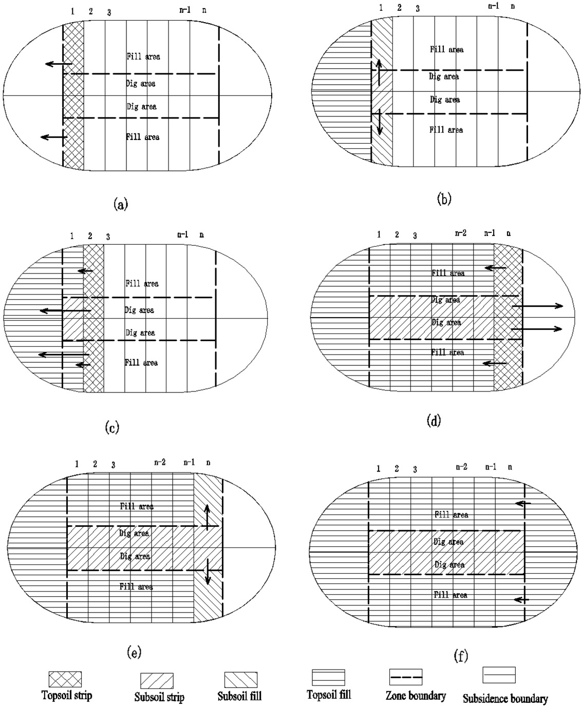
Schematic diagram of dynamic reclaimed soil reconstruction.
In order to facilitate the construction, the work area for dynamic reclamation should be divided into several zones firstly, then the zones should be separated into deep and shallow areas. The work of digging the deep to fill the shallow should be carried out within one zone, and soil reconstruction should be done zone by zone. The detailed procedure for soil reconstruction is shown in the following.
Firstly, the topsoil of zone one should be stripped and preserved in Part one (Figure 5a). Next, the subsoil of the area for a pond should be excavated to fill the shallow area for farmland (Figure 5b). Then, the topsoil of the shallow area in zone two should be stripped to cover the area of farmland in zone one, and the topsoil of the deep area in zone two should be stripped and preserved in Part one (Figure 5c). After that, work of subsoil excavation and filling continued, and so on, the soil of other zones can be constructed as the above procedure. For the last several zones, the topsoil of deep area can be preserved in Part three (Figure 5d) for the reclamation work for the last zone(Figure 5e) and this Part (Figure 5f). The construction process is showed in Figure 5.
Based on the above work procedures, it can realize that the new reconstructed soil has the similar profile structure as local agricultural soil, and the work can be done with the process of mining work face advancing, meeting the requirements of dynamic reclamation.
4 Application analysis
4.1 Overview of research case
A mine in the east of China is chosen as an example to illustrate the dynamic reclamation design. The depth of the underground water level is 3 m in this area. The coal seam is a horizontal layer with thickness of 8.3 m(m=8.3 m) and burial depth of 420 m(H=420 m); The surface terrain is flat with an average elevation of 44 m(H0=44 m). The length of simulated work face is 1580 m (A=1580 m), and the width is 160 m (B=160 m). Coal is excavated by comprehensive mechanized mining method with even speed of 3 m/d (v=3 m/d). Based on the observation data of similar condition mine, the angle of subsidence is 59∘(δ0=59∘), and the angle of full subsidence is 46∘(ψ3=46∘), and the coefficient of maximum subsidence is 0.84 (q=0.84), and tangent value of major influence angle is 2 (tgβ=2). The fish breed requires that the depth of water in excess of 3 m, and the thickness of topsoil for stripping is 0.3m (h=0.3 m).
4.2 Parameters of dynamic reclamation
Based on the above methods, key technical parameters of dynamic reclamation are calculated as following.
4.2.1 Theoretical maximum subsidence
Because the width of work face does not reach the critical extraction value, the theoretical maximum subsidence is calculated with following formula.
Where,
Cym is the effective coefficient of strike direction, in this study, its value is 0.6604.
4.2.2 Division of subsidence area
Based on the result of subsidence predication, the length for reclamation along longitudinal direction is 2085 m, and the length along strike direction is 665 m.
According to the underground water level, the subsidence area is divided into three parts, the length of Part one and Part three are 285 m, and length of Part two is 1515 m.
4.2.3 Determination for the control time of soil excavation
Based on the requirement of aquaculture, the deep area for the pond needs to be further dug 1.4 m and topsoil thickness is 0.3 m. In order to avoid constructing under water, the critical value for temporary subsidence is Wt=1300 mm. Before reaching that value, the soil excavation shall be finished. Given the time of first-cut as 0, when the time is about 104 days (T1=104), Wt reaches the critical value. At this time, the distance from the work place to first-cut is 312 m.
4.2.4 Calculation for the parameters for land use
Based on the soil balance of excavation and fill, in the half profile, the length for pond is 75 m, and for farmland is 257.5 m. In order to compensate for the effect of residual subsidence, the inverse gradient in the farmland is 1%. According to the construction standard for farmland, the recommended width of the work zone is about 20-30 m.
4.3 Results analysis
4.3.1 Time save analysis
For the traditional reclamation, measures are taken until the completion of subsidence. Like the case in this study, it needs 4.3 years to reach surface stabilization. If using the dynamic reclamation method, the work of soil excavation work can end in 104 days after the start of mining. Then the ponds and farmlands can be used continuously. The period of abandonment is reduced by nearly 4 years. So, the dynamic reclamation method can significantly reduce the period of land waste.
4.3.2 Cost reduction analysis
In the mining area with the high groundwater level, if the reclamation was done until the subsidence ended, then, a lot of work would need to be carried out under the water, and the cost increased greatly. According to the budget quota of work, the cost for construction of soil excavation under water would increase by twice.
5 Discussion
5.1 Summary of the results
For the subsidence land in the area with the high underground water level, we set up a general mode for dynamic reclamation, and give a method to determine reclamation time for soil strip, and an optimization thought for land use. According to the theory of soil science, we propose a procedure for soil reconstruction. Then through case analysis, this dynamic reclamation method can reduce the cost and shorten the land waste time.
5.2 Explanation of the results
Based on the thought of dynamic reclamation, for the subsidence land in the area with high underground water level, before it sinks below the underground water level during the process of subsidence, the treatment should be done to protect the topsoil. This time for reclamation can be calculated with dynamic predication theory of mining subsidence. For subsidence land in the area of this type, a reasonable proportion of water and farmland use can economize investment and improve the land utilization. The main factor of earth balance is used to determine the ratio. The work procedure of soil reconstruction can ensure that the new soil in reclamation has the similar profile structure as local agricultural soil, and keep the land quality.
5.3 Comparison to previous literature and novelty
Dynamic reclamation method for surface mining began relatively early and some techniques have been applied to engineering practice [1, 2, 3, 4, 5]. However, most of the coal resources are exploited with the method underground mining in China at present. Dynamic reclamation for mining subsidence land just begin in recent years [3, 7]. Because the area with high underground water usually belongs to the good quality farmland, and the subsidence can cause the land destroyed seriously, and intensify the contradiction between human and land resources, the reclamation is becoming an urgent task. At present, research of dynamic reclamation mainly focuses on the time of reclamation [5, 6, 7]. Compared with the previous research results, the advantages of this study are that: 1) the construction conditions are considered to determine the reclamation time, then can prevent the underwater topsoil stripping and reduce the construction difficulty; 2) reasonably land use ratio of water and cultivated land in reclamation area can be calculated based on soil balance; 3) soil reconstruction can be carried out according to soil theory to ensure land quality.
5.4 Limitations
It should be noted that results of this study are gained under certain conditions. During actual application, conditions may be different, so the reclamation schema shall be modified based on the specific requirements. The core of dynamic reclamation for subsidence land is the mining subsidence prediction theory which is still in developing and there are many work to perfect it. So, dynamic reclamation can develop with improvement of mining subsidence prediction theory. However, the ideas provided in this paper are still useful to guide the future study.
6 Conclusions
Dynamic reclamation emphasizes that taking measures to reclamation during or before subsidence happens. It can control land degradation, and improve the efficiency of land use.This study focuses on dynamic reclamation techniques for the subsidence land on the requirements of land use and construction. The main results are as following:
(1) The method for determining the control time for soil excavation can be calculated based on the mine subsidence theories and the requirements of construction.
(2) The optimization thought for land use in the subsidence area is put forth with the principle of soil balance for reclamation.
(3) Soil reconstruction procedure for dynamic reclamation is established according to the treatment process.
(4) A general dynamic reclamation mode is proposed for subsidence land with high underground water level.
There are still a lot of problems need to be further studied according to specific conditions. I hope the research results can provide some help for reclamation development.
Acknowledgement
Acknowledgement: This work is financially supported by research project of Xi’an University of Science and Technology (2040102005). We are very grateful to two anonymous reviewers who provided constructive suggestions which led to improvement of the paper.
References
[1] Hu Z.Q., Bian Z.F., Cheng S., et al., Land reclamation and ecological reconstruction. China University of Mining and Technology Press, Xuzhou, 2008Search in Google Scholar
[2] Liang H.T, Zhang D.Y. , Li Y.J., The Summary of Land Reclamation Research in China. Journal of Anhui Agri. Sci.,2011, 30, 18793-18795, 18798 (in Chinese with English abstract)Search in Google Scholar
[3] Hu Z.Q., Xiao W.„ Wang P.J., Zhao Y.L., Concurrent mining and reclamation for underground coal mining. Journal of China Coal Society, 2013, 2, 301-307 (in Chinese with English abstract)Search in Google Scholar
[4] He G.Q., Yang L., Ling G.D, et al., Mining subsidence theory. China University of Mining and Technology Press, 1991, XuzhouSearch in Google Scholar
[5] Hu Z.J.,Wei Z.Y, Qin P., Concept and methods for soil reconstruction in mined land reclamation. Soils, 2005, 1, 8-12 (in Chinese with English abstract)Search in Google Scholar
[6] Xiao W., Wang P.J., Wang X.J, Yu Y., Chen C., Topsoil stripping strategy for concurrent mining and reclamation construction in high groundwater coal mines based on GIS. China Mining Magazine, 2014, 4, 97-100 (in Chinese with English abstract)Search in Google Scholar
[7] Zhao Y.L., Hu Z.Q., Proper time model for pre-reclamation of unstable subsidence. Journal of China Coal Society, 2008, 2, 157-161 (in Chinese with English abstract)Search in Google Scholar
[8] Peng X.Z., Cui X.M., Zang Y.Q, et al., Time function and prediction of progressive surface movements and deformations. Journal of University of Science and Technology Beijing, 2004, 4, 341-344 (in Chinese with English abstract)Search in Google Scholar
[9] Cui X.M., Wang J & Liu Y, Prediction of progressive surface subsidence above longwall coal mining using a time function. International Journal of Rock Mechanics & Mining Sciences, 2001, 2, 1057-63 (in Chinese with English abstract)10.1016/S1365-1609(01)00061-2Search in Google Scholar
[10] Hu Z.Q., Xiao W.„ Optimization of concurrent mining and reclamation plans for single coal seam:a case study in northern Anhui, China. Environmental Earth Sciences, 2013, 5, 247-1254 (in Chinese with English abstract)10.1007/s12665-012-1822-9Search in Google Scholar
[11] Zhang Y.M., Dai X.D, The application of dynamic reclamation in coal mining subsidence with high water table. Mine Surveying, 2004, 3, 49-51 (in Chinese with English abstract)Search in Google Scholar
© 2018 Q. Chen and M. Hang, published by De Gruyter
This work is licensed under the Creative Commons Attribution-NonCommercial-NoDerivatives 4.0 License.
Articles in the same Issue
- Regular Articles
- Spatio-temporal monitoring of vegetation phenology in the dry sub-humid region of Nigeria using time series of AVHRR NDVI and TAMSAT datasets
- Water Quality, Sediment Characteristics and Benthic Status of the Razim-Sinoie Lagoon System, Romania
- Provenance analysis of the Late Triassic Yichuan Basin: constraints from zircon U-Pb geochronology
- Historical Delineation of Landscape Units Using Physical Geographic Characteristics and Land Use/Cover Change
- ‘Hardcastle Hollows’ in loess landforms: Closed depressions in aeolian landscapes – in a geoheritage context
- Geostatistical screening of flood events in the groundwater levels of the diverted inner delta of the Danube River: implications for river bed clogging
- Utilizing Integrated Prediction Error Filter Analysis (INPEFA) to divide base-level cycle of fan-deltas: A case study of the Triassic Baikouquan Formation in Mabei Slope Area, Mahu Depression, Junggar Basin, China
- Architecture and reservoir quality of low-permeable Eocene lacustrine turbidite sandstone from the Dongying Depression, East China
- Flow units classification for geostatisitical three-dimensional modeling of a non-marine sandstone reservoir: A case study from the Paleocene Funing Formation of the Gaoji Oilfield, east China
- Umbrisols at Lower Altitudes, Case Study from Borská lowland (Slovakia)
- Modelling habitats in karst landscape by integrating remote sensing and topography data
- Mineral Constituents and Kaolinite Crystallinity of the <2 μm Fraction of Cretaceous-Paleogene/Neogene Kaolins from Eastern Dahomey and Niger Delta Basins, Nigeria
- Construction of a dynamic arrival time coverage map for emergency medical services
- Characterizing Seismo-stratigraphic and Structural Framework of Late Cretaceous-Recent succession of offshore Indus Pakistan
- Geosite Assessment Using Three Different Methods; a Comparative Study of the Krupaja and the Žagubica Springs – Hydrological Heritage of Serbia
- Use of discriminated nondimensionalization in the search of universal solutions for 2-D rectangular and cylindrical consolidation problems
- Trying to underline geotourist profile of National park visitors: Case study of NP Fruška Gora, Serbia (Typology of potential geotourists at NP Fruška Gora)
- Fluid-rock interaction and dissolution of feldspar in the Upper Triassic Xujiahe tight sandstone, western Sichuan Basin, China
- Calcified microorganisms bloom in Furongian of the North China Platform: Evidence from Microbialitic-Bioherm in Qijiayu Section, Hebei
- Spatial predictive modeling of prehistoric sites in the Bohemian-Moravian Highlands based on graph similarity analysis
- Geotourism starts with accessible information: the Internet as a promotional tool for the georesources of Lower Silesia
- Models for evaluating craters morphology, relation of indentation hardness and uniaxial compressive strength via a flat-end indenter
- Geotourism in an urban space?
- The first loess map and related topics: contributions by twenty significant women loess scholars
- Modeling of stringer deformation and displacement in Ara salt after the end of salt tectonics
- A multi-criteria decision analysis with special reference to loess and archaeological sites in Serbia (Could geosciences and archaeology cohabitate?)
- Speleotourism in Slovenia: balancing between mass tourism and geoheritage protection
- Attractiveness of protected areas for geotourism purposes from the perspective of visitors: the example of Babiogórski National Park (Poland)
- Implementation of Heat Maps in Geographical Information System – Exploratory Study on Traffic Accident Data
- Mapping War Geoheritage: Recognising Geomorphological Traces of War
- Numerical limitations of the attainment of the orientation of geological planes
- Assessment of runoff nitrogen load reduction measures for agricultural catchments
- Awheel Along Europe’s Rivers: Geoarchaeological Trails for Cycling Geotourists
- Simulation of Carbon Isotope Excursion Events at the Permian-Triassic Boundary Based on GEOCARB
- Morphometry of lunette dunes in the Tirari Desert, South Australia
- Multi-spectral and Topographic Fusion for Automated Road Extraction
- Ground-motion prediction equation and site effect characterization for the central area of the Main Syncline, Upper Silesia Coal Basin, Poland
- Dilatancy as a measure of fracturing development in the process of rock damage
- Error-bounded and Number-bounded Approximate Spatial Query for Interactive Visualization
- The Significance of Megalithic Monuments in the Process of Place Identity Creation and in Tourism Development
- Analysis of landslide effects along a road located in the Carpathian flysch
- Lithological mapping of East Tianshan area using integrated data fused by Chinese GF-1 PAN and ASTER multi-spectral data
- Evaluating the CBM reservoirs using NMR logging data
- The trends in the main thalweg path of selected reaches of the Middle Vistula River, and their relationships to the geological structure of river channel zone
- Lithostratigraphic Classification Method Combining Optimal Texture Window Size Selection and Test Sample Purification Using Landsat 8 OLI Data
- Effect of the hydrothermal activity in the Lower Yangtze region on marine shale gas enrichment: A case study of Lower Cambrian and Upper Ordovician-Lower Silurian shales in Jiangye-1 well
- Modified flash flood potential index in order to estimate areas with predisposition to water accumulation
- Quantifying the scales of spatial variation in gravel beds using terrestrial and airborne laser scanning data
- The evaluation of geosites in the territory of National park „Kopaonik“(Serbia)
- Combining multi-proxy palaeoecology with natural and manipulative experiments — XLII International Moor Excursion to Northern Poland
- Dynamic Reclamation Methods for Subsidence Land in the Mining Area with High Underground Water Level
- Loess documentary sites and their potential for geotourism in Lower Silesia (Poland)
- Equipment selection based on two different fuzzy multi criteria decision making methods: Fuzzy TOPSIS and fuzzy VIKOR
- Land deformation associated with exploitation of groundwater in Changzhou City measured by COSMO-SkyMed and Sentinel-1A SAR data
- Gas Desorption of Low-Maturity Lacustrine Shales, Trassic Yanchang Formation, Ordos Basin, China
- Feasibility of applying viscous remanent magnetization (VRM) orientation in the study of palaeowind direction by loess magnetic fabric
- Sensitivity evaluation of Krakowiec clay based on time-dependent behavior
- Effect of limestone and dolomite tailings’ particle size on potentially toxic elements adsorption
- Diagenesis and rock properties of sandstones from the Stormberg Group, Karoo Supergroup in the Eastern Cape Province of South Africa
- Using cluster analysis methods for multivariate mapping of traffic accidents
- Geographic Process Modeling Based on Geographic Ontology
- Soil Disintegration Characteristics of Collapsed Walls and Influencing Factors in Southern China
- Evaluation of aquifer hydraulic characteristics using geoelectrical sounding, pumping and laboratory tests: A case study of Lokoja and Patti Formations, Southern Bida Basin, Nigeria
- Petrography, modal composition and tectonic provenance of some selected sandstones from the Molteno, Elliot and Clarens Formations, Karoo Supergroup, in the Eastern Cape Province, South Africa
- Deformation and Subsidence prediction on Surface of Yuzhou mined-out areas along Middle Route Project of South-to-North Water Diversion, China
- Abnormal open-hole natural gamma ray (GR) log in Baikouquan Formation of Xiazijie Fan-delta, Mahu Depression, Junggar Basin, China
- GIS based approach to analyze soil liquefaction and amplification: A case study in Eskisehir, Turkey
- Analysis of the Factors that Influence Diagenesis in the Terminal Fan Reservoir of Fuyu Oil Layer in the Southern Songliao Basin, Northeast China
- Gravity Structure around Mt. Pandan, Madiun, East Java, Indonesia and Its Relationship to 2016 Seismic Activity
- Simulation of cement raw material deposits using plurigaussian technique
- Application of the nanoindentation technique for the characterization of varved clay
- Verification of compressibility and consolidation parameters of varved clays from Radzymin (Central Poland) based on direct observations of settlements of road embankment
- An enthusiasm for loess: Leonard Horner in Bonn and Liu Tungsheng in Beijing
- Limit Support Pressure of Tunnel Face in Multi-Layer Soils Below River Considering Water Pressure
- Spatial-temporal variability of the fluctuation of water level in Poyang Lake basin, China
- Modeling of IDF curves for stormwater design in Makkah Al Mukarramah region, The Kingdom of Saudi Arabia