Structural characterization and nanoscale strain field analysis of α/β interface layer of a near α titanium alloy
-
Longlong Lu
 ,
Kexing Song
,
Xiuhua Guo
,
Kexing Song
,
Xiuhua Guo

Abstract
In this article, the structural and nanoscale strain field of the α/β phase interface layer in Ti80 alloy were studied by using high-resolution transmission electron microscopy (HRTEM) and geometric phase analysis (GPA). The α/β interface layer was observed in forged and different annealed Ti80 alloys, which is mainly composed of lamellar face-centered cubic (FCC) phase region and α′ + β region. The FCC phases between α and β phases show a twin relationship, and the twinning plane is
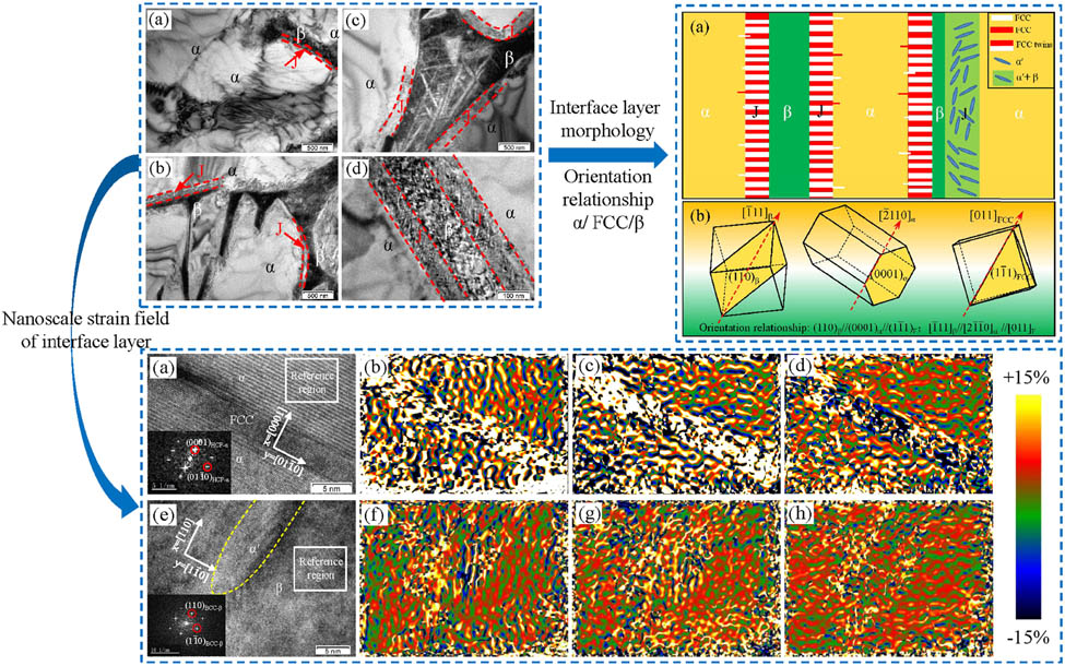
Graphical abstract
1 Introduction
Titanium and titanium alloys are widely used in aerospace, biomedicine, shipbuilding, and other fields due to their high specific strength, excellent corrosion resistance, and high-temperature mechanical properties [1,2,3,4]. The mechanical properties of titanium alloys are mainly controlled by phase composition [5,6], such as the α phase with hexagonal close-packed (HCP) structure, the β phase with body-centered cubic (BCC) structure, non-close-packed hexagonal ω phase, and so on. Recently, the α/β interface layers were observed in pure titanium and titanium alloys [7], which mainly composed of the face-centered cubic (FCC) phase [8]. However, currently, there is no systematic study on the interface layer and the FCC phase of near α titanium alloy.
Early scholars proposed that the interface layer and the FCC phase may be an artificial product formed during the preparation of thin foils examined for transmission electron microscopy [9,10]. However, soon after, Aguayo et al. [11] proposed the possibility of the FCC phase in a certain pressure based on first-principles investigations. Moreover, Zhu et al. [12] proved that the existence of the interface layer and the FCC phase by using in situ heating based on the high-temperature instability of Ti-hydride. Hong et al. [13] observed the stress-induced FCC phase in pure titanium and considered that the stress-induced phase transformation was attributed to the gliding of Shockley partial dislocations, which provides a new plastic deformation martensite transformation mode. In general, most stress-induced HCP → FCC phase transitions are caused by severe plastic deformation conditions, such as cryogenic channel-die compression, high energy shot peening, and cold rolling [14].
Recently, Zhao et al. [15] reported that the α/β interface layer hindered dislocation motion and formed deformed twins, which significantly decreased the mean free path for dislocation slip to improve the strength of Ti–6Al–4V titanium alloy. Bai et al. [16] observed that the FCC phase has undergone various deformation modes such as shearing, bending, kinking, and their combinations in the rolling process, and considered that the kinking of the FCC band structure could lead to grain refinement and improve ductility. In sum, the interface layer and the FCC phase have a significant effect on the microstructure and properties of titanium and titanium alloys.
In addition, alloying elements always have a significant effect on the phase stability and microstructure control of alloy. Sahara et al. [17] reported that the hcp phase was more stable than the bcc phase when V, Cr, and Nb were added, whereas the bcc phase was stabilized when Fe, Co, and Mo are added. Lu et al. [18] found that some metastable β phases began to appear, when 3 or 5 wt% Mo was added to Ti–6Al-based alloys. Jiang et al. [19] found that the microhardness, mechanical strength, and plasticity of Ti–Zr alloy were increased concurrently as the Zr addition increased, observed that the interactions of twins caused the brittle fracture of Ti20Zr alloy, and proposed that the FCC phase impeded dislocation slip effectively, thereby improving the strength plasticity of Ti30Zr alloy. It can be concluded that optimizing the type and the content of alloying elements is a significant way to design high-strength various alloys to meet the strict requirements of modern industry.
Currently, the studies on the α/β interface layer and the FCC phase of titanium alloys are mainly focused on pure titanium and Ti–6Al–4V titanium alloy. Moreover, the investigation on the formation mechanism of the FCC phase is also mainly concentrated on plastic deformation. As a significant method to strengthen the properties of titanium alloys, element addition also should have a complex influence on the α/β interface layer and the FCC phase. However, few scholars pay attention to the α/β interface layer and the FCC phase of multi-element near α titanium alloys. Moreover, the influence mechanism of the alloying elements on the formation of the FCC phase in titanium alloys is still unclear.
Multi-element near α titanium alloys always have more complex alloying elements and more excellent welding performance and impact toughness than pure titanium and Ti–6Al–4V titanium alloys. Studying the interface layer and the FCC phase of the multi-element near α titanium alloy is beneficial to control the microstructure and improve the comprehensive properties of near α titanium alloy. In addition, explaining the influence mechanism of elements on the FCC phase can be conducive to the design of titanium alloy with better properties by optimizing the composition of alloy elements. Therefore, it is necessary to study the interface layer and the FCC phase of the multi-element near α titanium alloy.
In this article, near α Ti80 titanium alloy with a nominal composition of Ti–6Al–3Nb–2Zr–1Mo was selected as the study material, which is developed by adjusting the element type of Ti–6Al–4V alloy [20,21]. The structure of the α/β interface layer of Ti80 alloys was studied by using TEM, and the orientation relationship of the α phase, the β phase, and the FCC phase of the alloy are determined. In addition, a nanoscale strain analysis of the interface layer and the FCC phase of the titanium alloy was first studied by using the geometry phase analysis (GPA). Finally, the element distribution of the α/β interface layer was observed by using scanning transmission electron microscopy (STEM), and the influence of alloying elements on the formation of the FCC phase was discussed. This study can provide a new idea for optimizing the microstructure and properties of titanium alloys.
2 Experimental procedure
The as-received material used in this investigation is forged Ti80 titanium alloy, which is prepared by vacuum arc melting and forging processes. The chemical composition of Ti80 alloy is presented in Table 1. The β-transus temperature of the alloy is 1,000°C
The chemical composition of Ti80 alloy (mass fraction, %)
| Sample | Ti | Al | Nb | Zr | Mo | N | H | O |
|---|---|---|---|---|---|---|---|---|
| Ti80 | Bal. | 6.50 | 3.18 | 2.04 | 1.17 | 0.0016 | 0.0060 | 0.113 |
The samples for metallographic observation were cut 15 mm × 15 mm × 15 mm from forged and annealed Ti80 alloy by using electric discharge wire-cutting technology. The specimens were polished and etched with a Kroll’s reagent (2%HF + 8%HNO3 + 90%H2O). Subsequently, some square sheets with a thickness of 0.3 mm and a side length of 10 mm were cut from the sample for TEM observation. The discs with a diameter of 3 mm were punched out after being mechanically thinned to 80 μm. The discs were further polished by twin-jet electropolishing technique. The electropolishing solution is composed of 5% perchloric, 35% butanol, and acid 60% methanol. The microstructure of Ti80 alloy was observed by using Zeiss axiovert A1 optical microscope (OM) and JEM-2100 transmission electron microscope, and then, the element distribution was analyzed by JEM-200F scanning transmission electron microscopy.
3 Results
3.1 Microstructural characteristics of Ti80 alloy with different states
Figure 1 shows the metallographic images of Ti80 alloy with different states. Light-colored blocks, light-colored needles, and dark-colored strips represent the primary α phase, secondary α phase, and residual β phase, respectively. Figure 1(a) shows the metallographic microstructure of the initial forged state. It can be observed that the grains are elongated, indicating the microstructure still retains the characteristics of forging deformation. In addition, some regions surrounded by the primary α phase have complex structures, which may include β phase, α′ phase, interfacial layer, and so on, which cannot be clearly observed under the metallurgical microscope, as marked by the white circle. Figure 1(b)–(d) shows the metallographic images of the alloy after 900°C × 1 h/A, 980°C × 1 h/AC, and 1,020°C × 1 h/AC, which present three typical microstructures of titanium alloys: equiaxed, bimodal, and lamellar state, respectively. Obviously, as the annealing temperature increases, the proportion and the thickness of the lamellar grains gradually increase and decrease, respectively, which should be attributed to the α → β phase transition of the alloy. In addition, there are also some complex α + β phase regions that cannot be clearly observed in Ti80 alloys with equiaxed, bimodal, and lamellar structures, which may contain the α/β interface layer, as shown by the red circle. In general, there may be an interface layer in the four Ti80 alloys, but it cannot be cleared from the metallographic images. Therefore, the TEM was used to observe the microstructure of Ti80 alloy with four different states.
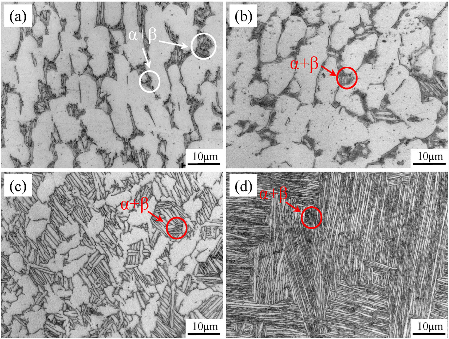
Metallographic images of Ti80 alloy: (a) as-forged, (b) 900°C × 1 h/AC, (c) 980°C × 1 h/AC, and (d) 1,020°C × 0.5 h/AC.
Figure 2 shows the TEM micrographs of Ti80 alloy with different states in different microstructure regions. It can be observed from Figure 2(a) that the interior of the α phase of forged Ti80 alloy comprised many dislocations. In addition, there is a short strip of β grain between two α grains, and a very narrow interface layer with a thickness of less than 200 nm (represented by J in figure) was observed between α phase and β phase. Figure 2(b) shows TEM micrographs of the trigeminal grain boundary region between α grains of equiaxed Ti80 alloy. It can be seen that the needle-like α′ phase is evenly distributed in the β phase, and there are interface layers with a thickness of about 200 nm between the trifurcated region and α grains. Figure 2(c) shows the TEM structure at the boundary between the α phase and the (α + β) region in Ti80 alloy with a bimodal structure. It also can be seen that the interface layer with a thickness of about 150 nm between α and β grains, which manifested as high-density dislocations. Figure 2(d) shows the lamellae α + β region of Ti80 alloy with a lamellar structure. An obvious interface layer with a thickness of about 80 nm between the lamellar α grain and the β grain can be found, which have a crystal structure different from matrix α and β phases. In addition, in various annealed Ti80 alloys, the dislocations in α phase almost disappear, but the interface layer and the β phase remain high-density dislocations. In general, it can be summarized that there are always interface layers between α and β in different microstructure regions of the alloy with different states. Moreover, the interface layer shows different thicknesses in different microstructure regions and is mainly manifested as high-density dislocation stripes.
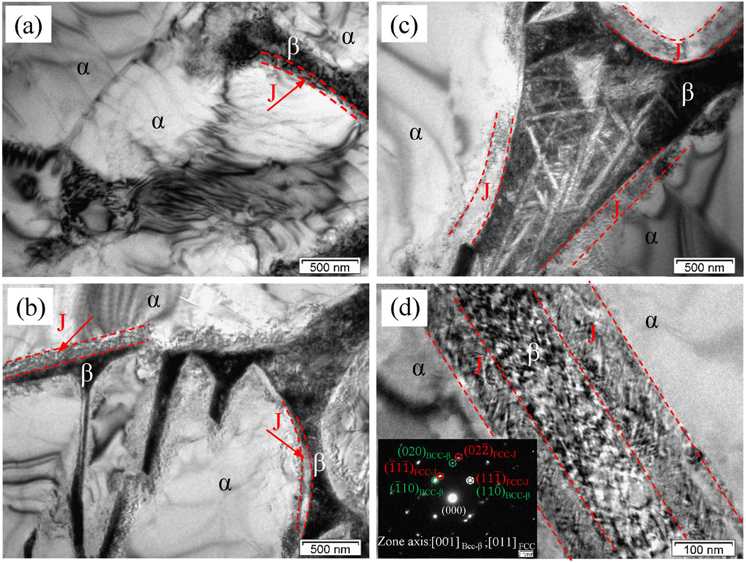
TEM micrographs of Ti80 alloy: (a) forged state (α and α grain region), (b) equiaxed state (trigeminal grain boundary region between equiaxed α grains), (c) bimodal state (α and α + β region), and (d) lamellar state (lamellar α + β region).
3.2 Structural characterization of α/β interface layer
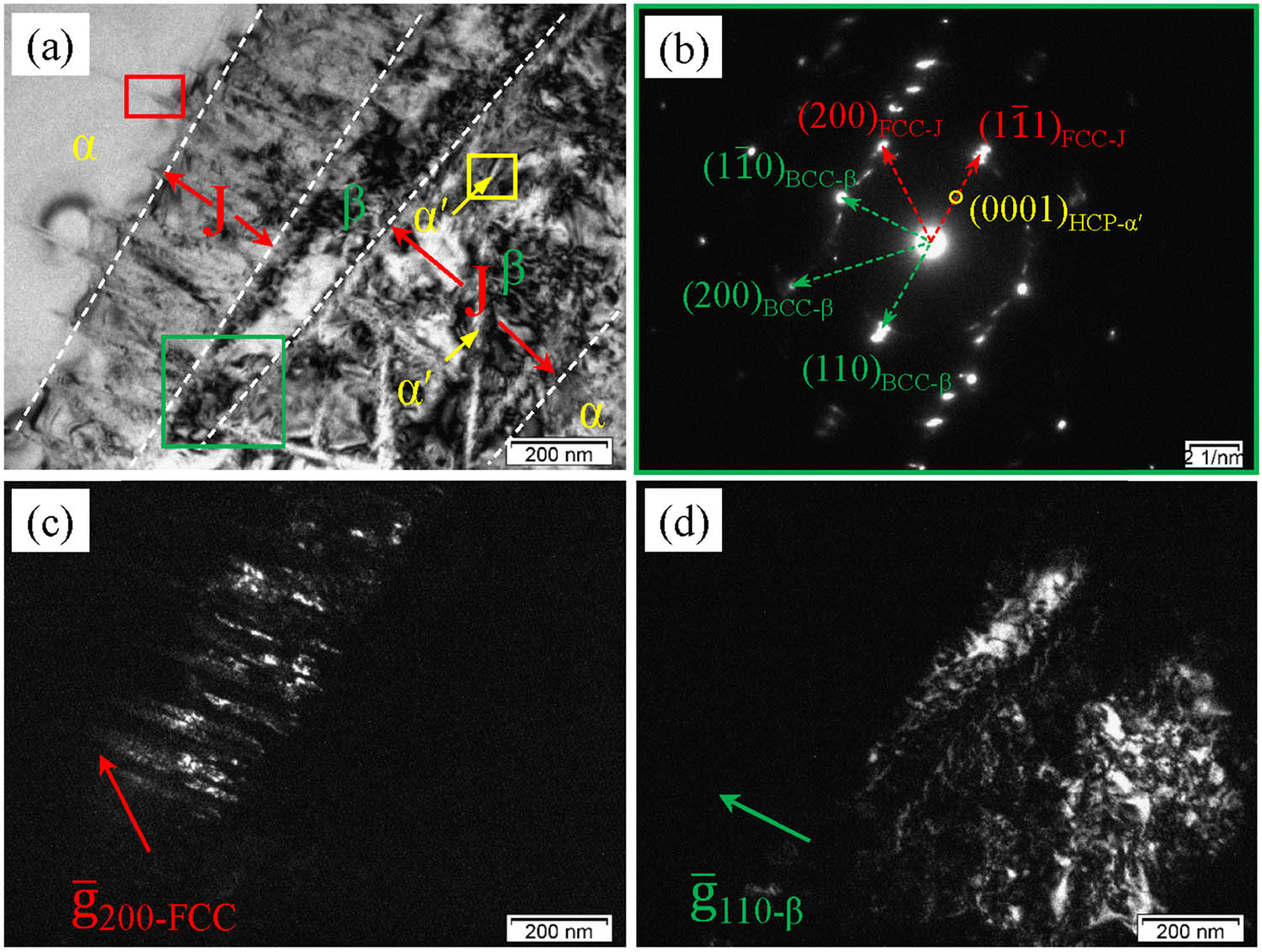
Figure 3 shows the TEM micrographs of the forged Ti80 alloy and the selected area electron diffraction (SAED) pattern. Figure 3(a) also shows that there is an interface layer with a thickness of about 280 nm between the α phase with some dislocation lines and the β phase with high-density dislocations. Figure 3(b) shows the SAED pattern in the red rectangle region. After calibration, it can be known that this region is mainly composed of body-centered cubic (BCC) structure β phase, hexagonal close-packed (HCP) structure α phase, and face-centered cubic structure FCC phase. At the same time, it can be known that the orientation relationship of the β phase, the α phase, and the FCC phase is (110)β//(0001)α//
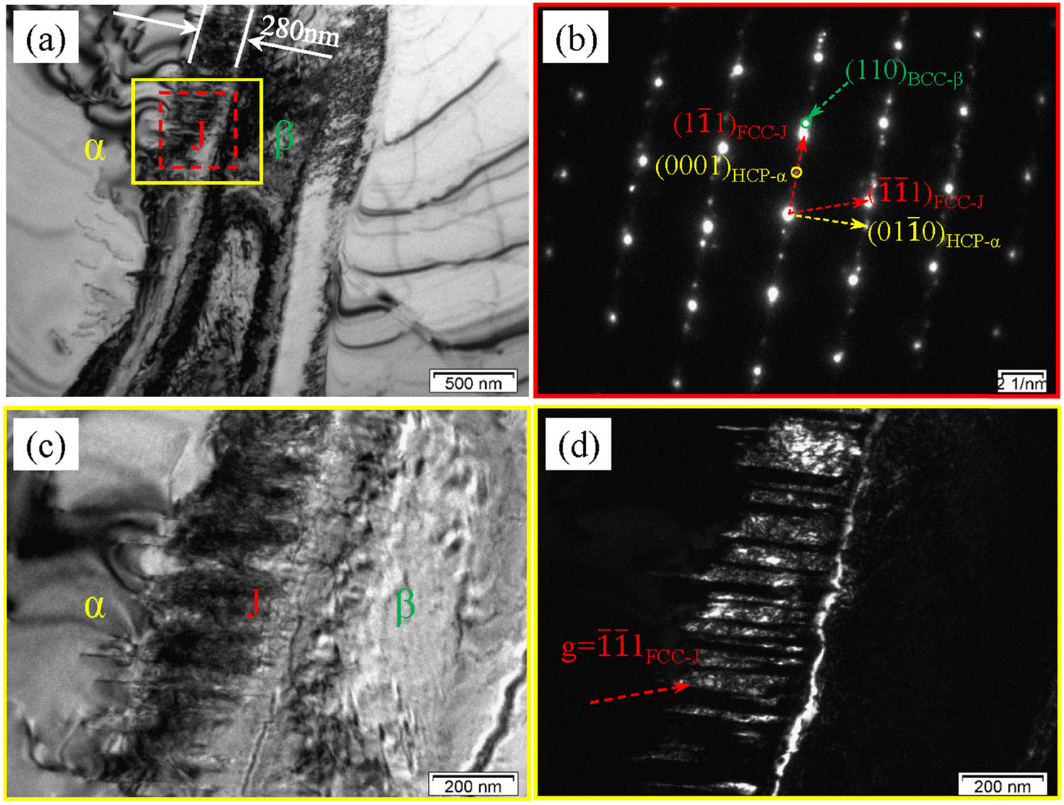
TEM micrographs of forged Ti80 alloy: (a) bright-field image, (b) selected area electron diffraction (SAED) in the red rectangle of (c), (c) partial magnification images of yellow rectangle of (c), and (d) the dark field image of (c).
To further study the lamellar FCC phase of the interface layer, HRTEM observation was carried out on the J region in Figure 3(a), as shown in Figure 4. Figure 4(a)–(c) shows the HRTEM image, the partial fast Fourier transformation (FFT) and the local inverse Fourier transform (IFFT) image. It can be confirmed that the lamellar FCC phases does have twin relationship, and the zone axis and the twin plane are [011] and (
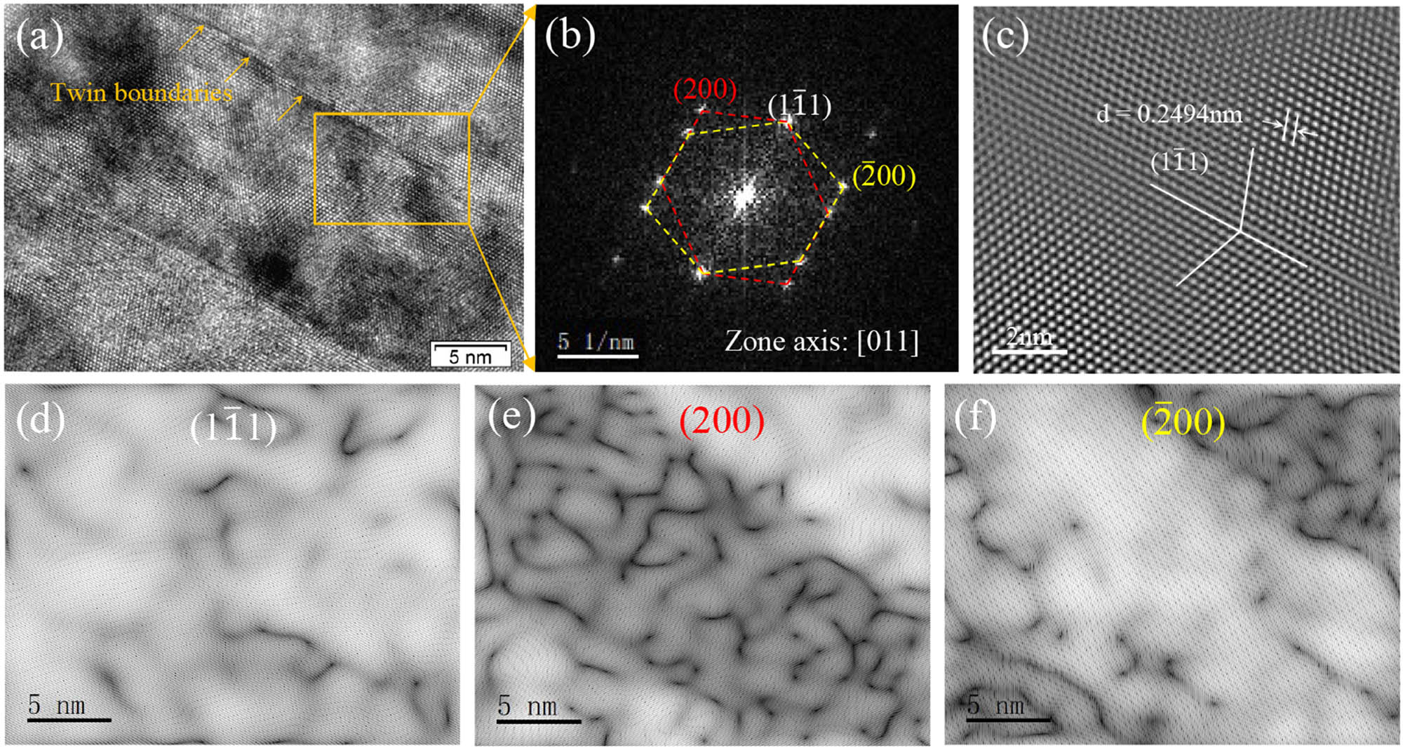
The partial HRTEM images of the J region of Figure 3(a) of: (a) HRTEM image of FCC phase, (b) FFT of orange rectangle in ©, (c) partial IFFT of (a), (d–f) (
Figure 5 shows the TEM micrographs of the disordered interface layer region in the forged Ti80 alloy. Figure 5(a) and (b) show a bright-field image and the partial SAED pattern. It can be observed from that the interface layer with a thickness of about 200 nm between the left of the stripe β phase and α phase, which is mainly composed of lamellar FCC phases. In addition, there is a 500 nm thick interface layer between the right of the stripe β phase and α phase has a different morphology and structure. The right interface layer is mainly composed of needle-like α′ phase and β phase with high-density dislocation. At the same time, the partial SAED pattern confirms that the orientation relationships among β phase, FCC phase, and α′ phase are (110)β//(
TEM micrographs of the disordered region in the forged Ti80 alloy: (a) bright-field image, (b) the SAED pattern in blue rectangle of (a), and (c) and (d) dark-field image of (a).
Figure 6(a) shows the HRTEM image and local lattice fringes of β and α′ phases. It can be seen that the lattice fringes of the β phase are relatively regular, while the lattice fringes of the needle-like α′ phase are arranged in a disorderly manner, indicating α′ phase has a high dislocation density. Generally speaking, the lattice parameter a and c of α′ phase are 0.308 and 0.47 nm, slightly higher than the lattice parameter of α phase (a = 0.2944 nm and c = 0.4678 nm), respectively. The generation of α′ phase is mainly related to the β → α phase transition during the cooling process [23]. Figure 6(b) shows the HRTEM image, FFT pattern, and local lattice fringes of the FCC phase and the α phase. It can be seen that the FCC phase located at the α/β interface layer gradually grows into α phase matrix along the [
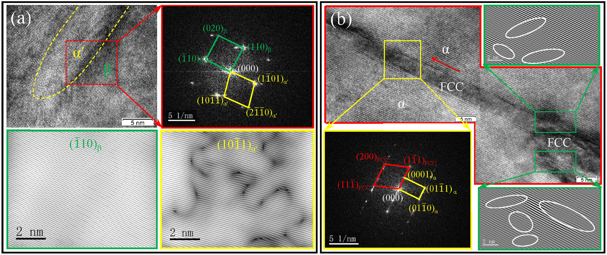
TEM micrographs of the yellow and red rectangle region in Figure 5(a): (a) the HRTEM image FFT pattern, (
Elements have a significant influence on the formation of the phase in titanium alloy [24]. Therefore, it is necessary to observe the element distribution of the alloy and study its influence on the formation of the interface layer. Figure 7 shows the elemental analysis of the lamellar α/β phases and the interface layer between the two phases. It can be found that Ti and Al elements are considerably concentrated in the α phase, and the distribution of Ti and Al elements in the α phase, the β phase, and the interface layer has a concentration gradient. Moreover, the gradient distribution of Al is more significant. The distribution of both Mo and Nb has a concentration in the β phase, especially the Mo element is more obvious. In addition, there is no obvious difference in the distribution of Zr elements in the α phase, the β phase, and the interface layer.
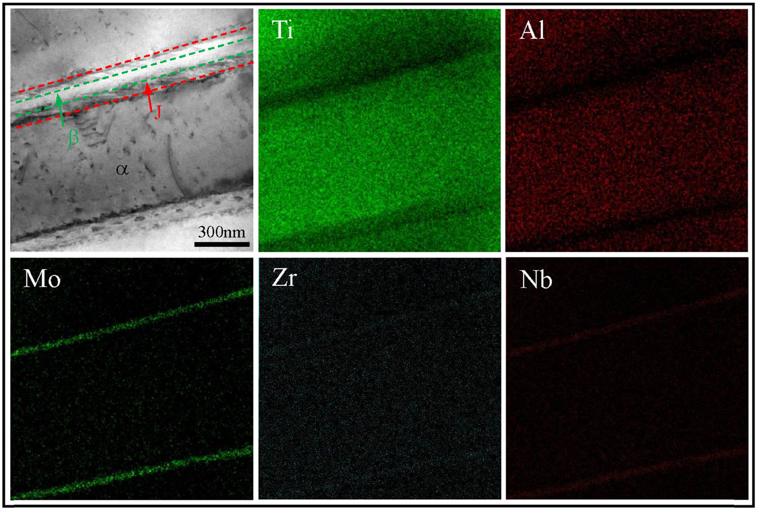
STEM element distribution diagram of forged Ti80 alloy.
4 Discussion
4.1 Nanoscale strain field analysis
A nanoscale strain field will be formed in the FCC + α and α′ + β regions due to the difference in their lattice constants. The strain field has a significant effect on hindering the movement of dislocations and the formation and the growth of precipitates [25]. In this study, the geometric phase analysis (GPA) was introduced to analyze the strain field of the α/β interface layer. GPA is an image-processing technique for measuring atomic displacements recorded in HRTEM images, and the displacement as small as 0.003 nm can be detected [26]. The principle of GPA is that the HRTEM images formed on a certain zone axis can be regarded as a series of interference fringes corresponding to the atomic plane, subsequently, the relevant strain information can be obtained by analyzing these interference fringes. Figure 8(a) and (e) shows HRTEM images of FCC + α and α′ + β regions, respectively. Figure 8(b)–(d) shows the strain fields of ε xx , ε xy , and ε yy corresponding to Figure 8(a), and Figure 8(f)–(h) show the strain fields of ε xx , ε xy , and ε yy corresponding to Figure 8(e). The positive value in Figure 8 represents tensile strain and vice versa represents compressive strain. It can be observed that the overall strain gradient of the FCC + α region is larger than the α′ + β region. Furthermore, it can be seen from Figure 8(a)–(d) that the internal of the FCC phase shows the considerable strain compared with the surrounding α phase matrix, indicating that the FCC phase undergoes severe lattice distortion during the formation process. In addition, the strain field components ε xx and ε xy of the FCC phase are mainly tensile strains, while the strain component ε yy is mainly compressive strain. It can be seen from Figure 8(e)–(f) that the internal strain of the α′ phase is larger than the β phase, the latter exhibits lower strain. In addition, the strain field components ε xx and ε xy of α′ phase are more significant than ε yy , and the high strain region of the component ε yy is mainly concentrated at the junction of α′ phase and β phase. In general, FCC + α region show more significant strain gradient than α′ + β region, and ε FCC > ε α, ε α′ > ε β.
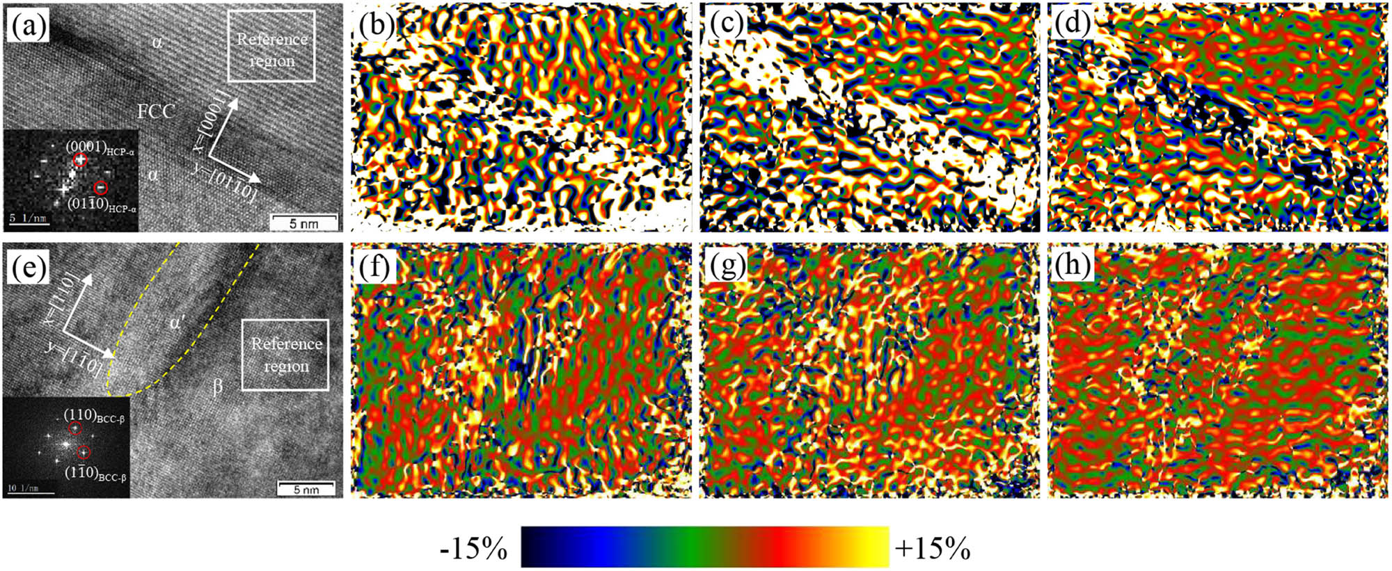
The strain fields of FCC + α and α′ + β regions obtained by the geometric phase analysis: (a) and (e) HRTEM images corresponding to FCC + α and α′ + β, (b–d) the strain component ε xx , ε xy , and ε yy of (a), and (f)–(h) the strain component ε xx , ε xy , and ε yy of (e).
4.2 Formation mechanism of FCC phase of the α/β interface layer
After the aforementioned analysis of the characterization and orientation relationship of the interface layer, the schematic diagram of microstructure morphology and orientation relationship of the interface layer was constructed, as shown in Figure 9. Currently, deformation-induced FCC phase formation has been clearly studied and mainly attributed to the sliding of Shockley partial dislocations [12]. However, in this study, it can be seen that not only the FCC phase appears in the forged Ti80 alloy but also in the annealed state, which proves that there should be other reasons leading and facilitating the FCC phase besides the deformation-induced phase transformation. Ti80 titanium alloy has more complex element types than pure titanium and Ti–6Al–4V alloy. To improve the mechanical properties of the alloy, Zr was added to Ti80 titanium alloy as a strengthening element. As generally known, the atomic radius of Zr is 0.162 nm larger than titanium (0.147 nm) [27], which will cause lattice distortion, and leads to a nanoscale strain field around the different atoms and interfaces/interphases. The interaction between the two strain fields may provide a driving force for the formation of the FCC phase. In addition, since Zr has lower the basal plane stacking fault energy than Ti [28], the addition of Zr may decrease the basal stacking fault energy of the α phase, thereby promoting the formation of the FCC phase. On the other hand, previous studies [29] have proposed that the interface FCC phase can be regarded as the intermediate phase in the β → α transformation process during the cooling of titanium alloy. The β phase-stabilizing elements such as Mo and V will generate a concentration gradient distribution due to its asymmetric diffusion during cooling [30], which will provide a chemical driving force for the FCC phase. However, in this study, it can be found from Figure 7 that there is no obvious concentration gradient of β phase stable elements (Mo and Nb), indicating that the FCC phase in this study should not be related to the concentration distribution of Mo and Nb. Moreover, it is interesting that there is an obvious concentration gradient of α phase-stabilizing element Al around the interface layer, which will cause the existence of stress around the α/β phase interface layer. The α/β interface layer will arise complex shear deformation under the effect of the chemical driving force, which leads to the formation of FCC twins. So, the concentration gradient of the Al element around the interface layer provides a chemical driving force for the formation of the FCC phase.
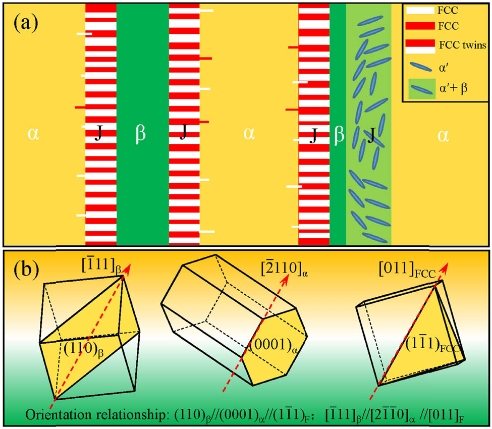
Schematic diagram of interface layer and FCC phase: (a) microstructure morphology and (b) orientation relationship.
5 Conclusion
The α/β interface layer was found in the forged, equiaxed, bimodal, and lamellar Ti80 alloy. The interface layer mainly exhibits high-density dislocations and is mainly composed of the lamellar FCC phase region and β + α′ region. The thickness of the FCC phase region of the interface layer is within the range of 300 nm, and the β + α′ region shows a larger thickness, approximately 500 nm.
There is a twin relationship between the FCC phases in the interface layer, and the twin plane is (1
The addition of elements has a significant effect on the formation of the FCC phase. The addition of Zr promotes the formation of the FCC phase by inducing lattice distortion and reducing the stacking fault energy of the α phase. In addition, the Al element forms a significant concentration gradient around the FCC phase of the α/β interface layer during the cooling process, which provides a driving force for the formation of the FCC phase.
-
Funding information: Henan Province “Innovative Science and Technology Team” Program (182101510003).
-
Author contributions: All authors have accepted responsibility for the entire content of this manuscript and approved its submission.
-
Conflict of interest: The authors state no conflict of interest.
References
[1] Zhang ZX, Fan JK, Tang B, Kou HC, Wang J, Wang X, et al. Microstructural evolution and FCC twinning behavior during hot deformation of high temperature titanium alloy Ti65. J Mater Sci Technol. 2020;49:56–69.10.1016/j.jmst.2020.02.026Search in Google Scholar
[2] Grishkov V, Kopylov V, Lotkov A, Latushkina S, Baturin A, Girsova N, et al. Effect of warm equal channel angular pressing on the structure and mechanical properties of Ti0.16Pd0.14Fe (wt%) alloy. Rev Adv Mater Sci. 2019;58:22–31.10.1515/rams-2019-0005Search in Google Scholar
[3] Jonas JJ, Aranas JC, Fall A, Jahazi M. Transformation softening in three titanium alloys. Mater Des. 2017;113:305–10.10.1016/j.matdes.2016.10.039Search in Google Scholar
[4] Lin NM, Xie RZ, Zou JJ, Qin JF, Wang YT, Yuan S. Surface damage mitigation of titanium and its alloys via thermal oxidation: a brief review. Rev Adv Mater Sci. 2019;58:132–46.10.1515/rams-2019-0012Search in Google Scholar
[5] Wang Q, Ren JQ, Wu YK, Jiang P, Li JQ, Sun ZJ, et al. Comparative study of crack growth behaviors of fully-lamellar and bi-lamellar Ti–6Al–3Nb–2Zr–1Mo alloy. J Alloys Compd. 2019;789:249–55.10.1016/j.jallcom.2019.02.302Search in Google Scholar
[6] Chen W, Lv YP, Zhang XY, Chen C, Lin YC, Zhou KC. Comparing the evolution and deformation mechanisms of lamellar and equiaxed microstructures in near β-Ti alloys during hot deformation. Mater Sci Eng A. 2019;758:71–8.10.1016/j.msea.2019.05.015Search in Google Scholar
[7] Zheng X, Gong MY, Xiong T, Ge HL, Yang LX, Zhou YT, et al. Deformation induced FCC lamellae and their interaction in commercial pure Ti. Scr Mater. 2019;162:326–30.10.1016/j.scriptamat.2018.11.037Search in Google Scholar
[8] Liu YG, Li MQ, Liu HJ. Deformation induced face-centered cubic titanium and its twinning behavior in Ti–6Al–4V. Scr Mater. 2016;119:5–8.10.1016/j.scriptamat.2016.03.018Search in Google Scholar
[9] Banerjee D, Williams JC. The effect of foil preparation technique on interface phase formation in Ti alloys. Scr Mater. 1983;17(9):1125–8.10.1016/0036-9748(83)90467-2Search in Google Scholar
[10] Banerjee D, Shelton CG, Ralph B, Williams JC. A resolution of the interface phase problem in titanium alloys. Acta Metall. 1988;36(1):125–41.10.1016/0001-6160(88)90033-8Search in Google Scholar
[11] Aguayo A, Murrieta G, Coss de R. Elastic stability and electronic structure of fcc Ti, Zr, and Hf: a first-principles study. Phys Rev B. 2002;65:092106.10.1103/PhysRevB.65.092106Search in Google Scholar
[12] Zhu W, Kou WJ, Tan CS, Zhang BY, Chen W, Sun QY, et al. Face centered cubic substructure and improved tensile property in a novel β titanium alloy Ti–5Al–4Zr–10Mo–3Cr. Mater Sci Eng A. 2020;771:138611.10.1016/j.msea.2019.138611Search in Google Scholar
[13] Hong DH, Lee TW, Lim SH, Kim WY, Hwang SK. Stress-induced hexagonal close-packed to face-centered cubic phase transformation in commercial-purity titanium under cryogenic plane-strain compression. Scr Mater. 2013;69(5):405–8.10.1016/j.scriptamat.2013.05.038Search in Google Scholar
[14] Kou W, Sun Q, Xiao L, Sun J. Plastic deformation-induced HCP-to-FCC phase transformation in submicron-scale pure titanium pillars. J Mater Sci. 2020;55(5):2193–201.10.1007/s10853-019-04043-0Search in Google Scholar
[15] Zhao Z, Chen J, Guo S, Tan H, Lin X, Huang W. Influence of α/β interface phase on the tensile properties of laser cladding deposited Ti–6Al–4V titanium alloy. J Mater Sci Technol. 2017;33(7):675–81.10.1016/j.jmst.2016.09.026Search in Google Scholar
[16] Bai FM, Yin LB, Zhao W, Zhou HW, Song M, Liu YC, et al. Deformational behavior of face-centered cubic (FCC) phase in high-pure titanium. Mater Sci Eng A. 2021;800:140287.10.1016/j.msea.2020.140287Search in Google Scholar
[17] Sahara R, Emura S, Tsuchiya K. Theoretical investigation of effect of alloying elements on phase stability in body-centered cubic Ti–X alloys (X = V, Cr, Fe, Co, Nb, and Mo). J Alloys Compd. 2015;634:193–9.10.1016/j.jallcom.2015.02.005Search in Google Scholar
[18] Lu JW, Ge P, Zhao YQ, Niu HZ. Structure and mechanical properties of Ti–6Al based alloys with Mo addition. Mater Sci Eng A. 2013;584:41–6.10.1016/j.msea.2013.07.013Search in Google Scholar
[19] Jiang J, Zhao YW, Wang XX. Effects of Zr addition on the deformation behavior, microstructure and mechanical properties of dental Ti alloys. Mater Sci Eng A. 2020;794:139808.10.1016/j.msea.2020.139808Search in Google Scholar
[20] Guo K, Meng K, Miao D, Wang Q, Zhang C, Wang T. Effect of annealing on microstructure and tensile properties of skew hot rolled Ti–6Al–3Nb–2Zr–1Mo alloy tube. Mater Sci Eng A. 2019;766:138346.10.1016/j.msea.2019.138346Search in Google Scholar
[21] Zhou DD, Zeng WD, Xu JW, Chen W, Wang SM. Characterization of hot workability for a near alpha titanium alloy by integrating processing maps and constitutive relationship. Adv Eng Mater. 2019;21(7):1801232.10.1002/adem.201801232Search in Google Scholar
[22] Su BX, Luo LS, Wang BB, Su YQ, Wang L, Ritchie RO, et al. Annealed microstructure dependent corrosion behavior of Ti–6Al–3Nb–2Zr–1Mo alloy. J Mater Sci Technol. 2021;62:234–48.10.1016/j.jmst.2020.05.058Search in Google Scholar
[23] Guo Q, Wang Q, Han XL, Lu XK, Sun DL, Wu GH. Precipitation behavior of α phase and mechanical properties in severely plastic deformed Ti–15–3 alloy. Rare Met Mater Eng. 2011;40(3):377–83.10.1016/S1875-5372(11)60019-2Search in Google Scholar
[24] Xu YQ, Fu Y, Li J, Xiao WL, Zhao XQ, Ma CL. Effects of tungsten addition on the microstructural stability and properties of Ti–6.5Al-2Sn-4Hf-2Nb-based high temperature titanium alloys. J Mater Sci Technol. 2021;93:147–56.10.1016/j.jmst.2021.02.057Search in Google Scholar
[25] Chen YF, Yang B, Zhou YT, Wu Y, Zhu HH. Evaluation of pitting corrosion in duplex stainless steel Fe20Cr9Ni for nuclear power application. Acta Mater. 2020;197:172–83.10.1016/j.actamat.2020.07.046Search in Google Scholar
[26] Chung J, Rabenberg L. A geometric phase analysis method dedicated to nanomaterials orienting along high-index zone axis. Micron. 2018;113:20–3.10.1016/j.micron.2018.06.010Search in Google Scholar PubMed
[27] Ji PF, Li B, Liu SG, Zhang X, Chen BH, Zhang XY, et al. Controlling the corrosion behavior of Ti–Zr alloy by tuning the α/β phase volume fraction and morphology of β phase. J Alloys Compd. 2020;825:154153.10.1016/j.jallcom.2020.154153Search in Google Scholar
[28] Ji PF, Chen BH, Li B, Tang YH, Zhang GF, Zhang XY, et al. Influence of Nb addition on microstructural evolution and compression mechanical properties of Ti–Zr alloys. J Mater Sci Technol. 2021;69:7–14.10.1016/j.jmst.2020.03.092Search in Google Scholar
[29] Katzarov I, Malinov S, Sha W. Finite element modeling of the morphology of β to α phase transformation in Ti–6Al–4V alloy. Metall Trans A. 2002;33(4):1027–40.10.1007/s11661-002-0204-4Search in Google Scholar
[30] Huang C, Dean TA, Loretto MH. Interface phase in α2 and B2 boundaries in Ti–25Al–10Nb–3V–1Mo alloy. Mater Sci Technol. 1995;11(2):143–9.10.1179/026708395790164670Search in Google Scholar
© 2021 Longlong Lu et al., published by De Gruyter
This work is licensed under the Creative Commons Attribution 4.0 International License.
Articles in the same Issue
- Research Articles
- Improved impedance matching by multi-componential metal-hybridized rGO toward high performance of microwave absorption
- Pure-silk fibroin hydrogel with stable aligned micropattern toward peripheral nerve regeneration
- Effective ion pathways and 3D conductive carbon networks in bentonite host enable stable and high-rate lithium–sulfur batteries
- Fabrication and characterization of 3D-printed gellan gum/starch composite scaffold for Schwann cells growth
- Synergistic strengthening mechanism of copper matrix composite reinforced with nano-Al2O3 particles and micro-SiC whiskers
- Deformation mechanisms and plasticity of ultrafine-grained Al under complex stress state revealed by digital image correlation technique
- On the deformation-induced grain rotations in gradient nano-grained copper based on molecular dynamics simulations
- Removal of sulfate from aqueous solution using Mg–Al nano-layered double hydroxides synthesized under different dual solvent systems
- Microwave-assisted sol–gel synthesis of TiO2-mixed metal oxide nanocatalyst for degradation of organic pollutant
- Electrophoretic deposition of graphene on basalt fiber for composite applications
- Polyphenylene sulfide-coated wrench composites by nanopinning effect
- Thermal conductivity and thermoelectric properties in 3D macroscopic pure carbon nanotube materials
- An effective thermal conductivity and thermomechanical homogenization scheme for a multiscale Nb3Sn filaments
- Friction stir spot welding of AA5052 with additional carbon fiber-reinforced polymer composite interlayer
- Improvement of long-term cycling performance of high-nickel cathode materials by ZnO coating
- Quantum effects of gas flow in nanochannels
- An approach to effectively improve the interfacial bonding of nano-perfused composites by in situ growth of CNTs
- Effects of nano-modified polymer cement-based materials on the bending behavior of repaired concrete beams
- Effects of the combined usage of nanomaterials and steel fibres on the workability, compressive strength, and microstructure of ultra-high performance concrete
- One-pot solvothermal synthesis and characterization of highly stable nickel nanoparticles
- Comparative study on mechanisms for improving mechanical properties and microstructure of cement paste modified by different types of nanomaterials
- Effect of in situ graphene-doped nano-CeO2 on microstructure and electrical contact properties of Cu30Cr10W contacts
- The experimental study of CFRP interlayer of dissimilar joint AA7075-T651/Ti-6Al-4V alloys by friction stir spot welding on mechanical and microstructural properties
- Vibration analysis of a sandwich cylindrical shell in hygrothermal environment
- Water barrier and mechanical properties of sugar palm crystalline nanocellulose reinforced thermoplastic sugar palm starch (TPS)/poly(lactic acid) (PLA) blend bionanocomposites
- Strong quadratic acousto-optic coupling in 1D multilayer phoxonic crystal cavity
- Three-dimensional shape analysis of peripapillary retinal pigment epithelium-basement membrane layer based on OCT radial images
- Solvent regulation synthesis of single-component white emission carbon quantum dots for white light-emitting diodes
- Xanthate-modified nanoTiO2 as a novel vulcanization accelerator enhancing mechanical and antibacterial properties of natural rubber
- Effect of steel fiber on impact resistance and durability of concrete containing nano-SiO2
- Ultrasound-enhanced biosynthesis of uniform ZnO nanorice using Swietenia macrophylla seed extract and its in vitro anticancer activity
- Temperature dependence of hardness prediction for high-temperature structural ceramics and their composites
- Study on the frequency of acoustic emission signal during crystal growth of salicylic acid
- Controllable modification of helical carbon nanotubes for high-performance microwave absorption
- Role of dry ozonization of basalt fibers on interfacial properties and fracture toughness of epoxy matrix composites
- Nanosystem’s density functional theory study of the chlorine adsorption on the Fe(100) surface
- A rapid nanobiosensing platform based on herceptin-conjugated graphene for ultrasensitive detection of circulating tumor cells in early breast cancer
- Improving flexural strength of UHPC with sustainably synthesized graphene oxide
- The role of graphene/graphene oxide in cement hydration
- Structural characterization of microcrystalline and nanocrystalline cellulose from Ananas comosus L. leaves: Cytocompatibility and molecular docking studies
- Evaluation of the nanostructure of calcium silicate hydrate based on atomic force microscopy-infrared spectroscopy experiments
- Combined effects of nano-silica and silica fume on the mechanical behavior of recycled aggregate concrete
- Safety study of malapposition of the bio-corrodible nitrided iron stent in vivo
- Triethanolamine interface modification of crystallized ZnO nanospheres enabling fast photocatalytic hazard-free treatment of Cr(vi) ions
- Novel electrodes for precise and accurate droplet dispensing and splitting in digital microfluidics
- Construction of Chi(Zn/BMP2)/HA composite coating on AZ31B magnesium alloy surface to improve the corrosion resistance and biocompatibility
- Experimental and multiscale numerical investigations on low-velocity impact responses of syntactic foam composites reinforced with modified MWCNTs
- Comprehensive performance analysis and optimal design of smart light pole for cooperative vehicle infrastructure system
- Room temperature growth of ZnO with highly active exposed facets for photocatalytic application
- Influences of poling temperature and elongation ratio on PVDF-HFP piezoelectric films
- Large strain hardening of magnesium containing in situ nanoparticles
- Super stable water-based magnetic fluid as a dual-mode contrast agent
- Photocatalytic activity of biogenic zinc oxide nanoparticles: In vitro antimicrobial, biocompatibility, and molecular docking studies
- Hygrothermal environment effect on the critical buckling load of FGP microbeams with initial curvature integrated by CNT-reinforced skins considering the influence of thickness stretching
- Thermal aging behavior characteristics of asphalt binder modified by nano-stabilizer based on DSR and AFM
- Building effective core/shell polymer nanoparticles for epoxy composite toughening based on Hansen solubility parameters
- Structural characterization and nanoscale strain field analysis of α/β interface layer of a near α titanium alloy
- Optimization of thermal and hydrophobic properties of GO-doped epoxy nanocomposite coatings
- The properties of nano-CaCO3/nano-ZnO/SBR composite-modified asphalt
- Three-dimensional metallic carbon allotropes with superhardness
- Physical stability and rheological behavior of Pickering emulsions stabilized by protein–polysaccharide hybrid nanoconjugates
- Optimization of volume fraction and microstructure evolution during thermal deformation of nano-SiCp/Al–7Si composites
- Phase analysis and corrosion behavior of brazing Cu/Al dissimilar metal joint with BAl88Si filler metal
- High-efficiency nano polishing of steel materials
- On the rheological properties of multi-walled carbon nano-polyvinylpyrrolidone/silicon-based shear thickening fluid
- Fabrication of Ag/ZnO hollow nanospheres and cubic TiO2/ZnO heterojunction photocatalysts for RhB degradation
- Fabrication and properties of PLA/nano-HA composite scaffolds with balanced mechanical properties and biological functions for bone tissue engineering application
- Investigation of the early-age performance and microstructure of nano-C–S–H blended cement-based materials
- Reduced graphene oxide coating on basalt fabric using electrophoretic deposition and its role in the mechanical and tribological performance of epoxy/basalt fiber composites
- Effect of nano-silica as cementitious materials-reducing admixtures on the workability, mechanical properties and durability of concrete
- Machine-learning-assisted microstructure–property linkages of carbon nanotube-reinforced aluminum matrix nanocomposites produced by laser powder bed fusion
- Physical, thermal, and mechanical properties of highly porous polylactic acid/cellulose nanofibre scaffolds prepared by salt leaching technique
- A comparative study on characterizations and synthesis of pure lead sulfide (PbS) and Ag-doped PbS for photovoltaic applications
- Clean preparation of washable antibacterial polyester fibers by high temperature and high pressure hydrothermal self-assembly
- Al 5251-based hybrid nanocomposite by FSP reinforced with graphene nanoplates and boron nitride nanoparticles: Microstructure, wear, and mechanical characterization
- Interlaminar fracture toughness properties of hybrid glass fiber-reinforced composite interlayered with carbon nanotube using electrospray deposition
- Microstructure and life prediction model of steel slag concrete under freezing-thawing environment
- Synthesis of biogenic silver nanoparticles from the seed coat waste of pistachio (Pistacia vera) and their effect on the growth of eggplant
- Study on adaptability of rheological index of nano-PUA-modified asphalt based on geometric parameters of parallel plate
- Preparation and adsorption properties of nano-graphene oxide/tourmaline composites
- A study on interfacial behaviors of epoxy/graphene oxide derived from pitch-based graphite fibers
- Multiresponsive carboxylated graphene oxide-grafted aptamer as a multifunctional nanocarrier for targeted delivery of chemotherapeutics and bioactive compounds in cancer therapy
- Piezoresistive/piezoelectric intrinsic sensing properties of carbon nanotube cement-based smart composite and its electromechanical sensing mechanisms: A review
- Smart stimuli-responsive biofunctionalized niosomal nanocarriers for programmed release of bioactive compounds into cancer cells in vitro and in vivo
- Photoremediation of methylene blue by biosynthesized ZnO/Fe3O4 nanocomposites using Callistemon viminalis leaves aqueous extract: A comparative study
- Study of gold nanoparticles’ preparation through ultrasonic spray pyrolysis and lyophilisation for possible use as markers in LFIA tests
- Review Articles
- Advance on the dispersion treatment of graphene oxide and the graphene oxide modified cement-based materials
- Development of ionic liquid-based electroactive polymer composites using nanotechnology
- Nanostructured multifunctional electrocatalysts for efficient energy conversion systems: Recent perspectives
- Recent advances on the fabrication methods of nanocomposite yarn-based strain sensor
- Review on nanocomposites based on aerospace applications
- Overview of nanocellulose as additives in paper processing and paper products
- The frontiers of functionalized graphene-based nanocomposites as chemical sensors
- Material advancement in tissue-engineered nerve conduit
- Carbon nanostructure-based superhydrophobic surfaces and coatings
- Functionalized graphene-based nanocomposites for smart optoelectronic applications
- Interfacial technology for enhancement in steel fiber reinforced cementitious composite from nano to macroscale
- Metal nanoparticles and biomaterials: The multipronged approach for potential diabetic wound therapy
- Review on resistive switching mechanisms of bio-organic thin film for non-volatile memory application
- Nanotechnology-enabled biomedical engineering: Current trends, future scopes, and perspectives
- Research progress on key problems of nanomaterials-modified geopolymer concrete
- Smart stimuli-responsive nanocarriers for the cancer therapy – nanomedicine
- An overview of methods for production and detection of silver nanoparticles, with emphasis on their fate and toxicological effects on human, soil, and aquatic environment
- Effects of chemical modification and nanotechnology on wood properties
- Mechanisms, influencing factors, and applications of electrohydrodynamic jet printing
- Application of antiviral materials in textiles: A review
- Phase transformation and strengthening mechanisms of nanostructured high-entropy alloys
- Research progress on individual effect of graphene oxide in cement-based materials and its synergistic effect with other nanomaterials
- Catalytic defense against fungal pathogens using nanozymes
- A mini-review of three-dimensional network topological structure nanocomposites: Preparation and mechanical properties
- Mechanical properties and structural health monitoring performance of carbon nanotube-modified FRP composites: A review
- Nano-scale delivery: A comprehensive review of nano-structured devices, preparative techniques, site-specificity designs, biomedical applications, commercial products, and references to safety, cellular uptake, and organ toxicity
- Effects of alloying, heat treatment and nanoreinforcement on mechanical properties and damping performances of Cu–Al-based alloys: A review
- Recent progress in the synthesis and applications of vertically aligned carbon nanotube materials
- Thermal conductivity and dynamic viscosity of mono and hybrid organic- and synthetic-based nanofluids: A critical review
- Recent advances in waste-recycled nanomaterials for biomedical applications: Waste-to-wealth
- Layup sequence and interfacial bonding of additively manufactured polymeric composite: A brief review
- Quantum dots synthetization and future prospect applications
- Approved and marketed nanoparticles for disease targeting and applications in COVID-19
- Strategies for improving rechargeable lithium-ion batteries: From active materials to CO2 emissions