Thermal aging behavior characteristics of asphalt binder modified by nano-stabilizer based on DSR and AFM
-
Xiaolong Sun
 ,
Junshen Yuan
,
Junshen Yuan

Abstract
In order to clarify the effect of thermal aging on the nano-stabilized modified asphalt binder, TINUVIN 770 (T770) hindered amine light stabilizer of nanoscale was selected as aging modifying agent to prepare modified asphalt. The impact of thermal aging on the rheological properties of T770-modified asphalt was investigated using dynamic shear rheological test of frequency sweep and multiple stress creep recovery test. The surface roughness variation of T770-modified asphalt was characterized by using atomic force microscope throughout the thermal aging process. Furthermore, the typical morphology and parameter features of T770-modified asphalt were identified. The results showed that with the extension of thermal aging time, the high temperature rutting resistance of T770-modified asphalt was improved, while the unrecoverable creep compliance was degraded. When the thermal aging time exceeded 6 h, the bee structure appeared on the surface of T770-modified asphalt. Meanwhile, with the increase in thermal aging time, the special structure formed on the surface of asphalt gradually became smaller. The surface fluctuation difference of T770-modified asphalt reflected the better thermal aging resistance property of T770-modified asphalt than 70# asphalt.
1 Introduction
Asphalt pavement is being widely used in urban roads and highways because of the driving comfort, easy maintenance, and rapid setting time for traffic [1,2,3]. However, the western region of China has typical regional climate characteristics, such as strong ultraviolet radiation, long sunshine duration, and large temperature difference [4]. Among them, ultraviolet radiation is a key factor that would accelerate the aging of asphalt materials significantly and exacerbate the cracks and looseness of asphalt pavement [5,6,7,8], which would affect the durability and service function of road pavement inevitably. Therefore, controlling the ultraviolet aging behavior of asphalt materials effectively is crucial for the sustainable development of transportation infrastructure in the western region of China and other regions worldwide.
As a new type of anti-UV aging modifying agent, hindered amine light stabilizer (HALS), which could capture active free radicals and quench singlet oxygen groups, inhibits the UV-induced chemical component transformation that improves the anti-UV aging performance of carrier materials [9,10]. However, asphalt is considered as a typical binder with viscoelastic properties [11], whose chemical composition is extremely complex and different from polymer materials of definite molecular chain configuration and polymerization degree. Moreover, the continuous thermal effect during the modifying process of asphalt might lead to negative impact on the modifying effect of HALS on asphalt. Therefore, the excellent modifying application of HALS in polymer materials could not be borrowed for HALS used in the ultraviolet aging control of asphalt pavement materials, which might build barrier for maintaining the efficient and stable aging control effect of HALS on asphalt material. The core to solve this problem is to clarify the effect of HALS on the mechanical properties, microstructure, and chemical composition of asphalt materials.
Ultraviolet response behavior is the correlation change in asphalt material properties from microscopic level to macroscopic level when exposed to ultraviolet radiation. At the macro level, mechanical properties are the direct reflection of the response behavior of asphalt materials to UV radiation, which are also important indices to evaluate the UV aging controlling effect of anti-UV aging-modified asphalt. Scholars at home and abroad have carried out relevant studies on the mechanical property variation in UV-aged asphalt. Currently, rheology, as an important indicator of the viscoelastic properties, has become the research focus of UV aging response of asphalt materials. Xiao et al. [12] found that ultraviolet aging could induce the viscoelastic ratio variation in asphalt leading to the deterioration of rheological properties. Aiming at the rheological evaluation indices of UV-aged asphalt, Zhang et al. [13] analyzed and determined the applicability of rheological indices such as rutting factor, zero shear viscosity, and loss shear modulus in the evaluation of UV aging behavior. Wu et al. [14,15,16,17] clarified the influence of ultraviolet radiation intensity, frequency, and temperature on the UV aging behavior of asphalt based on rheological properties and infrared spectroscopy. Furthermore, they also determined the UV aging depth of asphalt materials when subjected to ultraviolet radiation. In the aspect of microstructure characterization of light stabilizer-modified asphalt, some scholars used high resolution microscopy to characterize the microstructure variation in light stabilizer-modified asphalt. Shen et al. [18] and Menapace et al. [19] applied atomic force microscopy (AFM) to investigate the impact of ultraviolet radiation on the microstructure and components of the modified asphalt, which indicated that asphalt and its components represented different microstructures under the condition of different UV aging times and there were significant differences in the nanosize of the typical microstructure. Li et al. [20] found that the size of bee-structure in asphalt increased, while the number decreased after UV aging. Moreover, the results indicated that the UV light of 350–370 nm had the greatest effect on the number and size of bee structure than the UV light of other bands. Yu et al. [21] and Zadshir et al. [22] found that microcracks appearing on the surface of the UV-aged asphalt would gradually extend along with the expansion of UV aging time. The microstructure variation in UV-aged asphalt presented the generation process of its structural defects, which provided the micromorphology basis for further exploration of UV aging behavior. Thus, the current research on the microstructure of anti-UV aging-modified asphalt mainly focuses on the variation in the rheological properties and microstructure of asphalt after UV aging. However, the thermal aging could not be avoided in production process of asphalt pavement material, which might lead to the negative impact on the modifying effect of HALS on asphalt. Therefore, it is necessary to clarify the impact of thermal aging on the property and microstructure of HALS-modified asphalt.
In this article, T770 HALS was selected to prepare the modified asphalt and the thermal aging treatment of T770-modified asphalt was executed. The dynamic shear rheological test (DSR) was performed to analyze the influence of thermal aging on T770-modified asphalt and the AFM was carried out to characterize the microstructure variation in T770-modified asphalt under different thermal aging conditions. Therefore, this study would provide references for determining the properties and microstructure variation in HALS-modified asphalt after the high temperature preparing process.
2 Materials and methodology
2.1 Materials
2.1.1 Light stabilizer
T770 light stabilizer (bis(2,2,6,6-tetramethylpiperidiny)sebacate) was selected as the modifying agent to prepare HALS-modified asphalt. For improving the dispersion of light stabilizer in asphalt, the T770 of nanoscale was selected in this study. To characterize the microstructure and roughness of aged asphalt accurately, the content of T770 was expanded to 3% by the weight of asphalt (about 6–8 times by the normal content). The technical properties of T770 light stabilizer are shown in Table 1.
Technical properties of T770 light stabilizer
| Light stabilizer | Density (g cm−3) | Melting point (°C) | Viscosity (150°C) (Pa) | Specific heat capacity (J kg−1 °C−1) |
|---|---|---|---|---|
| T770 | 1.1 | 81–85 | 26.5 | 1,390 (20°C)/2,170 (100°C) |
2.1.2 Asphalt
70# asphalt was selected as binding material for the preparation of T770-modified asphalt to eliminate the interference of other modifiers on the test results. The technical properties of 70# asphalt are shown in Table 2.
Technical properties of 70# asphalt
| Technical indices | Value | Specification |
|---|---|---|
| Softening point (°C) | 50.4 | >43 |
| Penetration (25°C, 100 g, 5 s)/0.1 mm | 71 | 60–80 |
| Ductility (10°C) (cm) | 32 | >15 |
| Thin film oven test | ||
| Residual penetration ratio (%) | 57.2 | ≥54 |
| Softening point increment (°C) | 5.9 | — |
| Residual ductility (cm) | 7.3 | ≥4 |
2.1.3 Preparation of T770-modified asphalt and specimen
2.1.3.1 T770-modified asphalt
70# asphalt was put into heating oven of 110°C constant temperature and kept for 3 h. Then, a certain amount of asphalt was weighed and placed in a clean container and then the container was put on the oil bath heating device at 160 ± 5°C. The T770 light stabilizer was weighed and equally divided into three parts. The molten asphalt was sheared and stirred by the high-speed shear apparatus. The first portion of T770 was added and stirred at the shear rate of 2,000 rad min−1 for 5 min. The second and third portions of T770 were added and stirred at the shear rate of 1,200 rad min−1 for 5 min and 2,000 rad min−1 for 7 min, respectively. Finally, the T770-modified asphalt was stirred at 600 rad min−1 for 8 min and then the asphalt specimen was poured after the swelling of modified asphalt was completed. Details of the preparation process of T770-modified asphalt are shown in Figure 1.
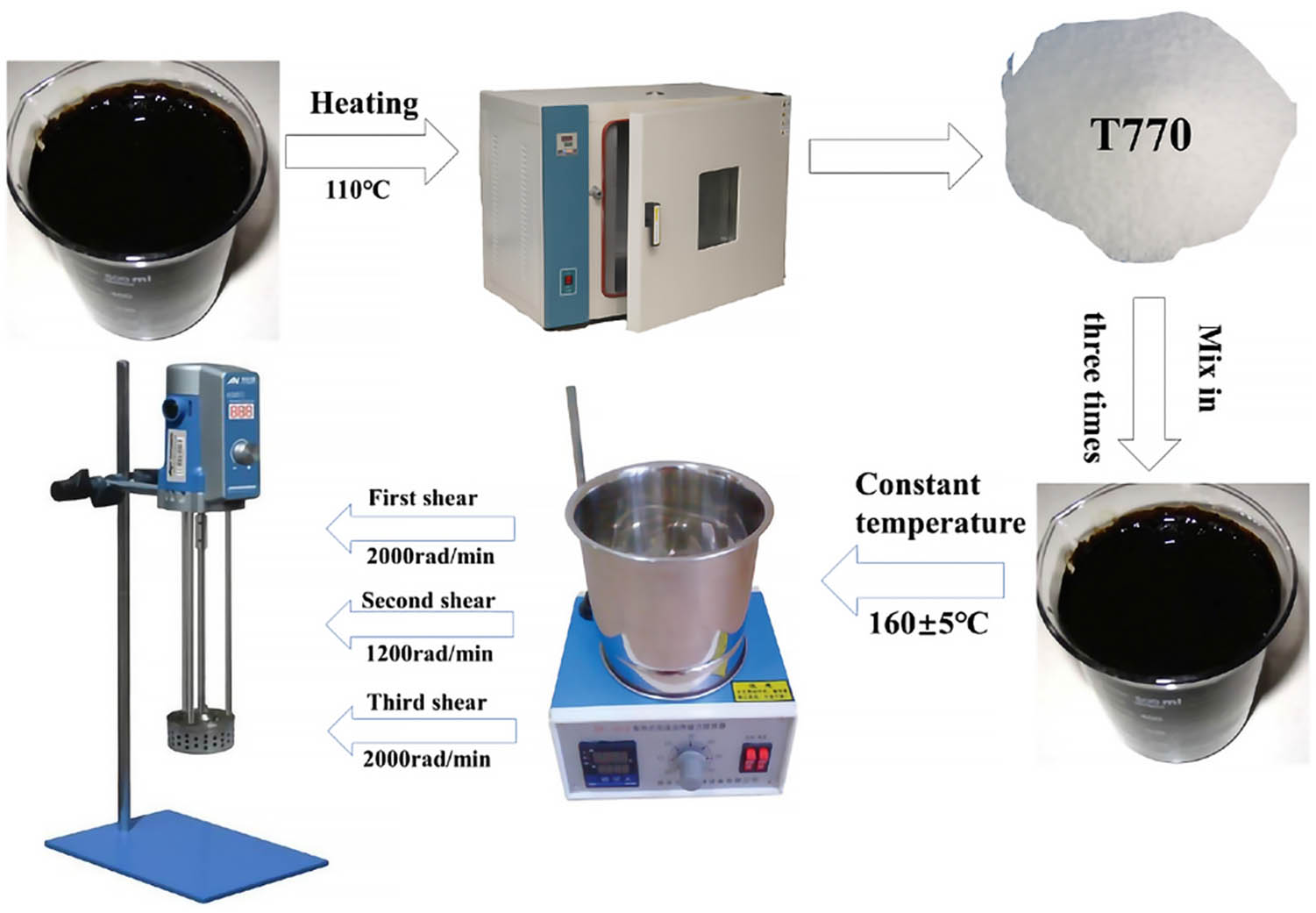
Preparation process of T770-modified asphalt.
2.1.3.2 Testing specimen preparation
The prepared asphalt was poured into the open cube container made of tin paper and then put into the oven for thermal aging treatment. According to the mixing process of matrix asphalt, the temperature was set to 120°C and the aging times were 1, 2, 3, 6, 9, 18, and 36 h. The AFM test specimen was prepared by hot drop method. The specific process was as follows: 1 cm × 1 cm asphalt specimen was obtained through cutting and put into a container made of tin paper. After heating to the flow pattern, the drop tube was used to absorb the modified asphalt and drop it in the carrier glass immediately. Then, the carrier glass continued to be heated on the heater to make it self-leveled and cooled in the closed box.
2.2 Methodology
2.2.1 DSR test
2.2.1.1 Frequency sweep
Smartpave102 DSR produced by Anton Paar was used for frequency scanning of T770-modified asphalt. The frequency scanning adopted the strain controlling mode and the strain was controlled to 1%. The frequency scanning test was carried out from 0.1 to 100 rad s−1 at 60°C. The diameter of scanning parallel plate was 25 mm and the spacing control was 1 mm.
2.2.1.2 Multiple stress creep recover (MSCR) test
MSCR test was used to evaluate the anti-rutting ability of T770-modified asphalt at high temperatures. According to AASHTO T 350 [23], the test temperature was set to 64°C, the diameter of parallel plate was 25 mm, and the spacing was 1 mm. During the MSCR test, the stress level of 0.1 and 3.2 kPa would be repeated for 20 times and 10 times, respectively. Every level included 10 cycles, which consisted of 1 s creep stage and 9 s unloading recovery stage per cycle that would last for 300 s. The evaluating indices were recovery rate (R) and unrecoverable creep compliance (J nr). The recovery rate (R 0.1 and R 3.2) and unrecoverable creep compliance (J nr0.1 and J nr3.2) of each cycle were calculated by formulas (1)–(2). The calculation formulas were as follows:
where τ is the duration of each cycle; γ p is the peak strain in each loading cycle; γ nr is the residual strain in each loading cycle; γ 0 is the initial strain in each loading cycle; J 0.1 is the unrecoverable creep compliance at 0.1 kPa stress level; J 3.2 is the unrecoverable creep compliance at 3.2 kPa stress level.
2.2.2 AFM test
AFM test was performed using the Dimension FastScan scanning probe microscope produced by Bruker Company, as shown in Figure 2. The maximum scanning ranges of fast and slow scanning modes were 30 μm × 30 μm and 90 μm × 90 μm, respectively. The test was carried out in the ScanAsyst intelligent mode and the AFM test results were analyzed by NanoScope Analysis software. For mitigating the impact of surface data error in the scanning process, the two-dimensional AFM images of modified asphalt were processed by second order flatten to ensure data consistency.
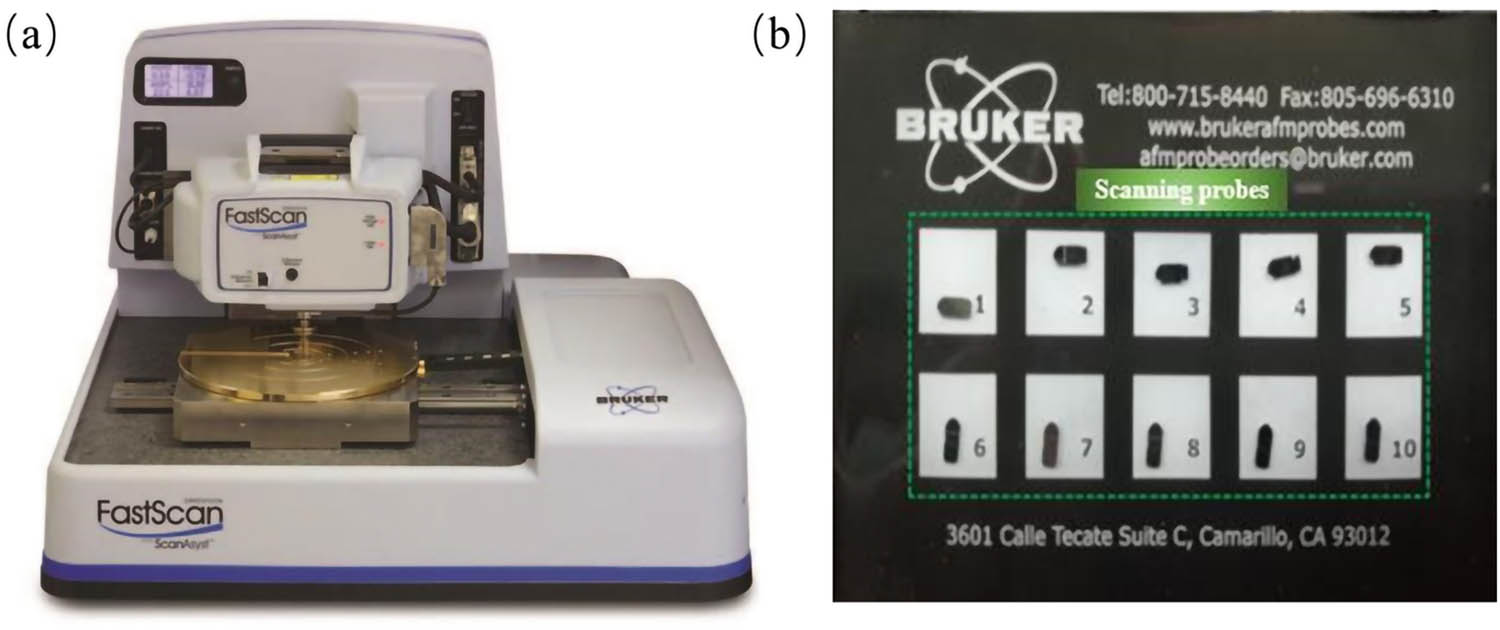
AFM testing equipment: (a) AFM instrument and (b) scanning probes.
3 Results and discussion
3.1 Rheological properties of thermal-aged asphalt
3.1.1 Frequency sweeping results
3.1.1.1 Matrix asphalt
The frequency scanning results of matrix asphalt in different thermal aging periods are shown in Figure 3. From Figure 3(a) and (c), it could be observed that the complex shear modulus G* and rutting factor |G*|/sin δ of aged asphalt increased linearly as the frequency increased, while the slope of the curve increased gradually from 0.24 to 0.59 with the extension of aging time, indicating that the longer the aging time was, the faster the growth rates of G* and |G*|/sin δ of asphaltwere. Regarding the consistent growth trend of each curve, a group of testing points (10 rad s−1) of different aged asphalts were selected to compare the corresponding rheological indices of variation curves, as shown in Figure 3(b) and (d) histogram. When the thermal aging time was 0–18 h, the G* and |G*|/sin δ of asphalt increased with the extension of aging time. At the thermal age of 18 h, the G* and |G*|/sin δ of asphalt increased about 1.41 times compared with the unaged asphalt. After aging for 18 h, the G* and |G*|/sin δ of asphalt tended to be stable. This might be because after thermal aging of asphalt, the content of heavy components in asphalt increased continuously, which enhanced the property of asphalt resisting shear deformation. As the impacting results, the G* and |G*|/sin δ of asphalt increased; however, as the thermal aging time continued to be extended, the content of light components in asphalt decreased gradually because of the transformation process. When the aging behavior of asphalt reached a certain degree, the transformation and volatilization of light components tended to be stable, and the shear deformation resistance of asphalt basically followed to be stable [24], which made G* and |G*|/sin δ no longer change. Figure 3(e) is the phase angle curve of thermal-aged asphalt. The curve analysis showed that the phase angle of aged asphalt decreased with the increase in frequency under different aging time conditions and the decrease rate between the curves was similar, indicating that the thermal aging time would not change the correlation and connection between the phase angle and frequency.
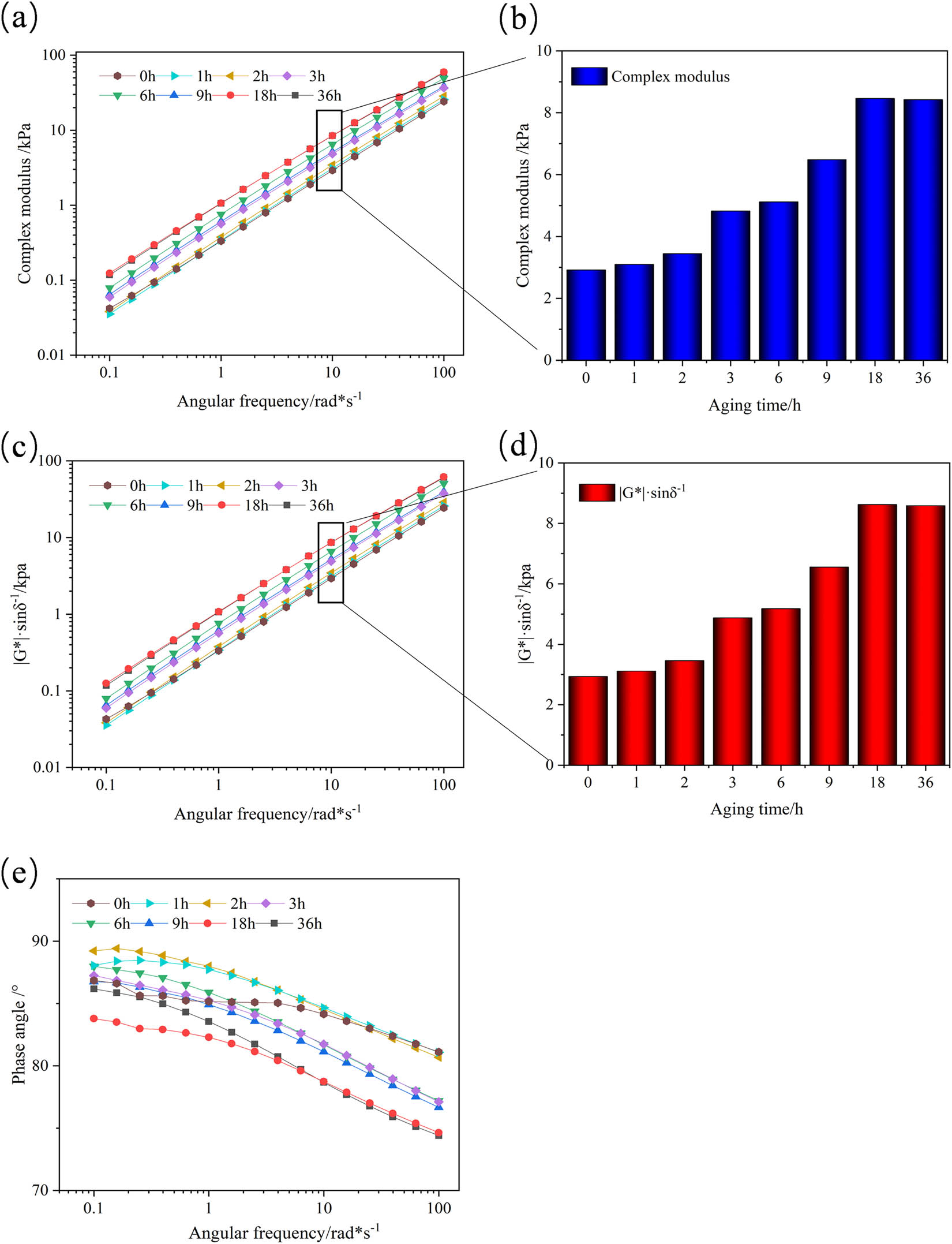
Frequency scanning results of matrix asphalt enduring different thermal aging times: (a) complex modulus; (b) complex modulus/10 rad s−1; (c) rutting factor; (d) rutting factor/10 rad s−1; and (e) phase angle.
3.1.1.2 T770-modified asphalt
Figure 4 shows the frequency sweep results of T770-modified asphalt subjected to different thermal aging times. According to the overall analysis in Figure 4, regardless of the aging state of the modified asphalt, the complex shear modulus G* and rutting factor |G*|/sin δ of T770-modified asphalt increased with the increase in frequency, while the phase angle δ decreased following the increase in frequency, indicating that the viscosity of asphalt was enhanced at high frequency. From Figure 4(a) and (c), it could be analyzed that the G* and |G*|/sin δ of T770-modified asphalt after thermal aging were higher than that of unaged modified asphalt, which reflected that the aged T770-modified asphalt had better rutting resistance than the unaged modified asphalt. According to the columnar diagram of Figure 4(b) and (d), the G* and |G*|/sin δ of unaged modified asphalt were the smallest and far less than that of modified asphalt aged for 1 h, and the difference was about 2.8 times. With the extension of thermal aging process, when the aging time was less than 6 h, the G* and |G*|/sin δ of T770-modified asphalt gradually decreased with the extension of aging time. After aging for more than 6 h, the G* and |G*|/sin δ of T770-modified asphalt increased linearly, and the slope was close to 1. This might be because that the addition of large amount of light stabilizer increased the content of light components (aromatic and saturated components) in unaged asphalt, and the viscosity of asphalt was weakened. Meanwhile, the value of δ was the maximum and the values of G* and |G*|/sin δ were the minimum, which presented the poor deformation resistance of unaged modified asphalt. When the thermal aging started, part of the aromatic components was volatilized under high temperature conditions. The content of the light components in the modified asphalt dropped sharply, which was significantly different from that without thermal aging, which indicated that the viscosity of modified asphalt was greatly improved. When the aging time was less than 6 h, the reason why G* and |G*|/sin δ of T770-modified asphalt decreased might be that the addition of T770 light stabilizer had certain improving effect on the thermal oxidative aging performance of asphalt, delaying the reactive free radical reaction in the aging process of asphalt, which promoted blocking the transformation of light components in asphalt to heavy components (asphaltene) [25]. When the aging time exceeded 6 h, the aging retardation effect of T770 in modified asphalt might reach the limit level, which was difficult to continue inhibiting the transformation of components in asphalt effectively, resulting in the instability of asphalt colloid structure and leading to the viscosity improvement in the modified asphalt.
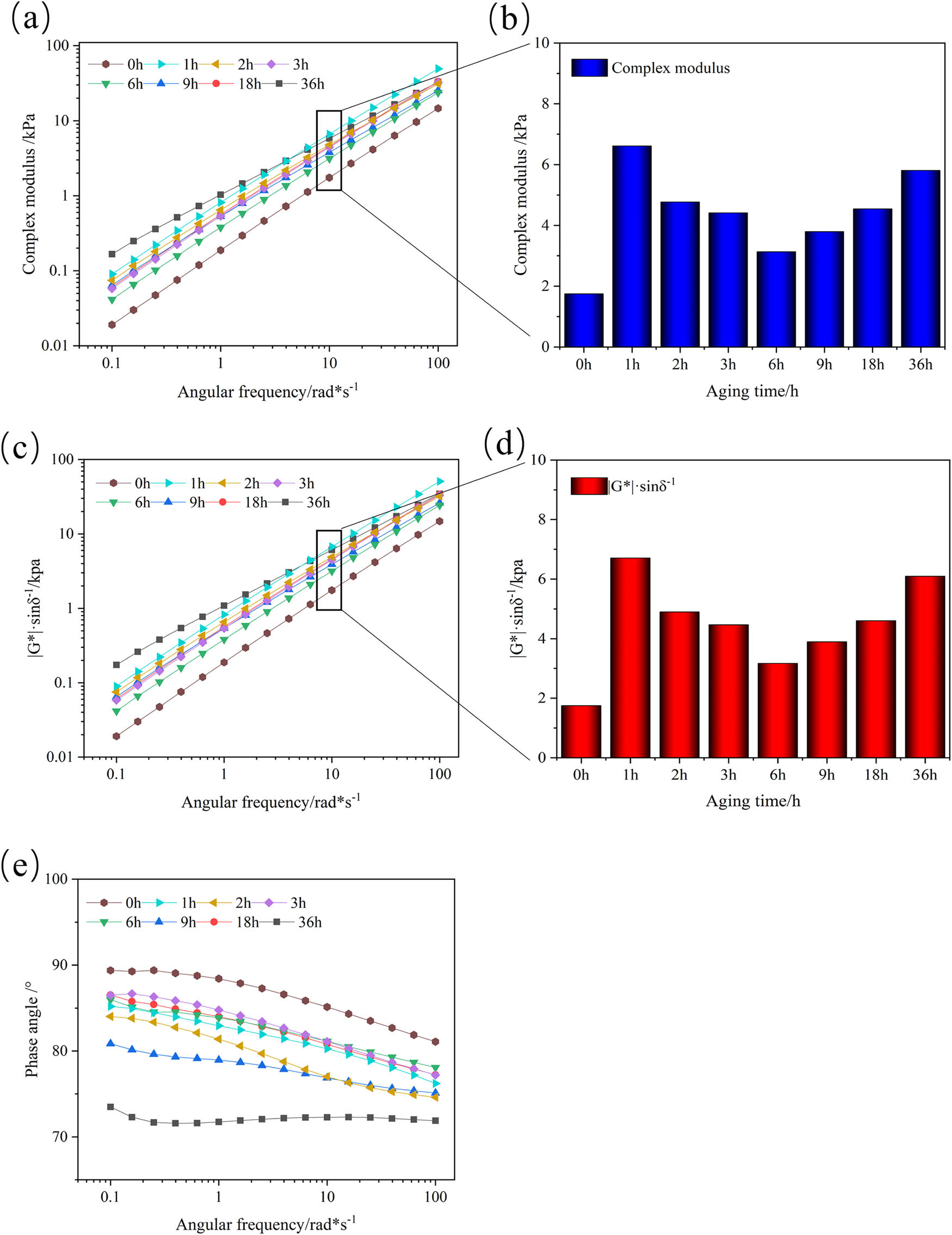
Frequency scanning results of T770-modified asphalt enduring different thermal aging times: (a) complex modulus; (b) complex modulus/10 rad s−1; (c) rutting factor; (d) rutting factor/10 rad s−1; and (e) phase angle.
3.1.2 MSCR results
3.1.2.1 Matrix asphalt
Figure 5 depicts the MSCR results of matrix asphalt subjected to different periods of thermal aging. From Figure 5(a) and (b), it could be observed that under the two stress levels, the cumulative strain of the unaged asphalt was greater than that of the aged asphalt. In order to better characterize the creep recovery status of aged asphalt under multiple stresses, the recovery rate R and the unrecoverable creep compliance J nr were calculated to analyze the strain resilience and permanent deformation resistance of aged asphalt.
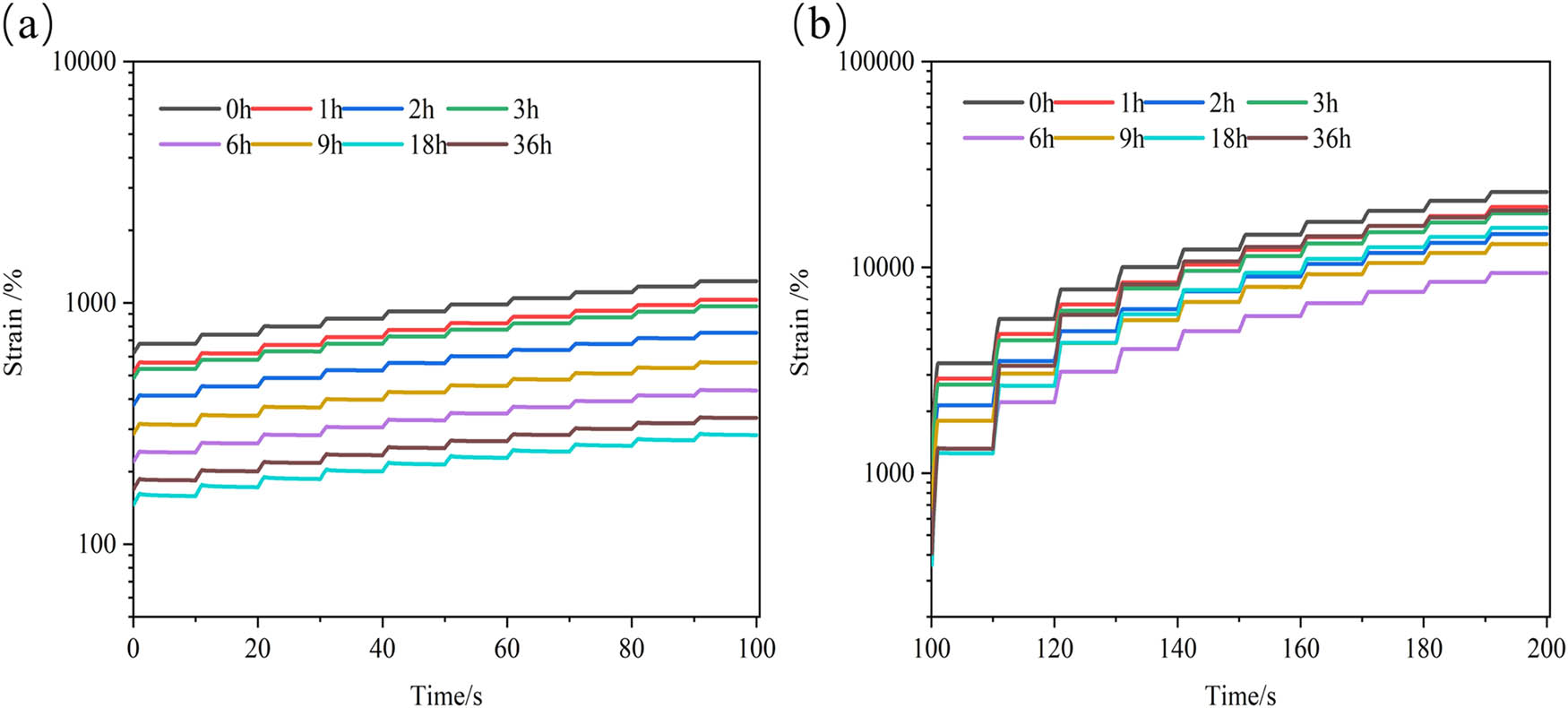
MSCR results of matrix asphalt enduring different thermal aging times: (a) 0.1 kPa and (b) 3.2 kPa.
Figure 6 shows the calculated results of unrecoverable creep compliance J nr and creep recovery rate R of thermal-aged asphalt. It could be seen from Figure 6(a) that under the load of 0.1 kPa stress, the J nr of the asphalt kept decreasing with the extension of aging time, and the R kept increasing during the aging period of 0–18 h. Compared with the 18 h thermal-aged asphalt, the J nr of unaged asphalt was reduced by about 74% and the R was increased by about 460%. When the aging time exceeded 18 h, the J nr and R values of thermal-aged asphalt tended to be stable. The reason was that the content of heavy component in asphalt increased after thermal aging, resulting in the improvement in elastic deformation and decrease in viscous deformation [26]. The permanent deformation resistance and creep recovery performance of asphalt were improved and the unrecoverable creep compliance was reduced. When the thermal aging of asphalt reached a certain degree, the content of heavy component was basically unchanged and the deformation recovery ability of asphalt tended to be stable, which was consistent with the frequency scanning results of matrix asphalt. In addition, under 3.2 kPa stress level, as the stress increased, the J nr of each thermal aging asphalt was increased and the R value was reduced by at least 80%, which indicated that the permanent deformation resistance of thermal-aged asphalt under high stress level would be significantly decreased and the creep recovery performance would be deteriorated.
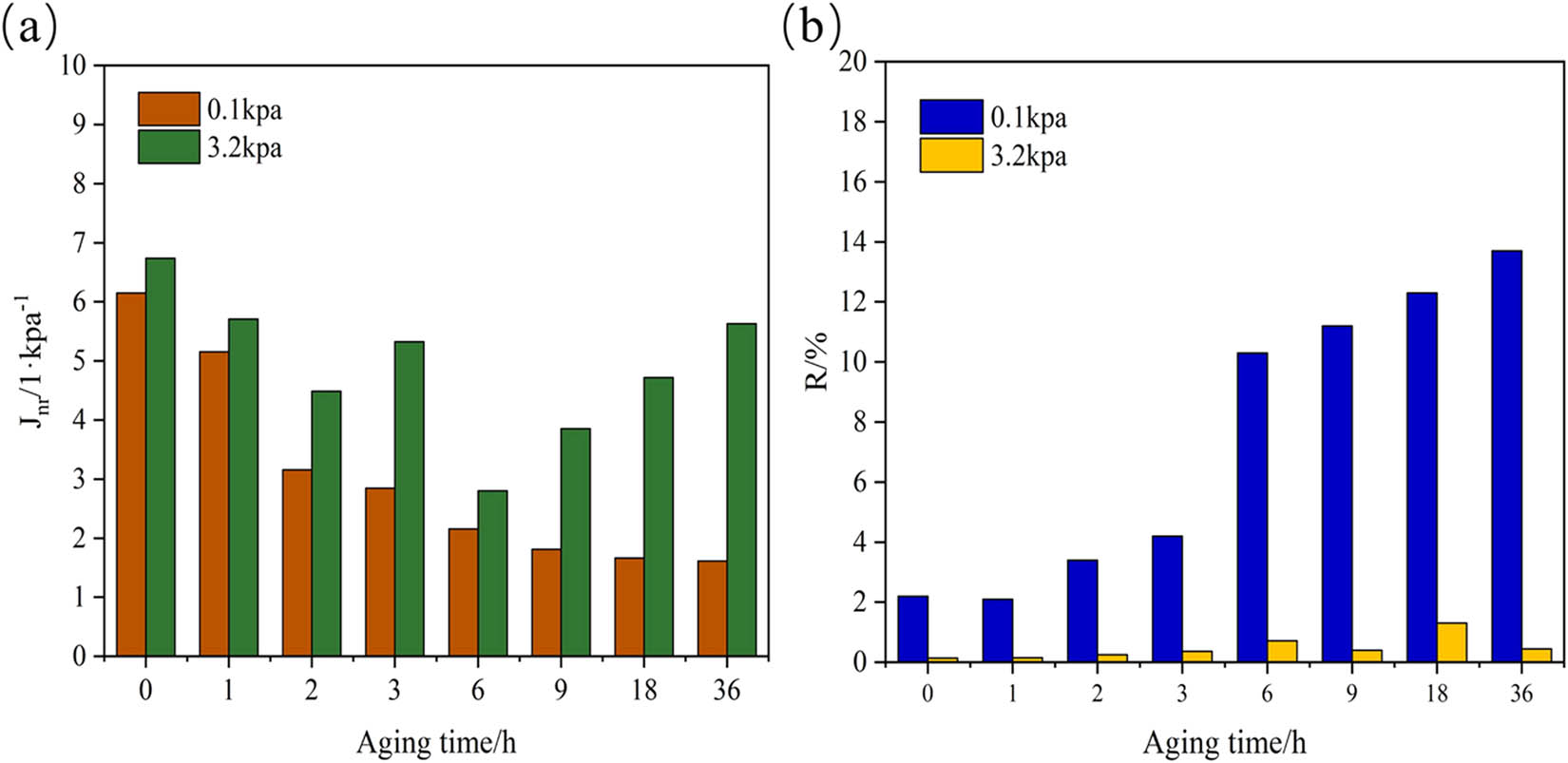
J nr and R of matrix asphalt enduring different thermal aging times: (a) J nr and (b) R.
3.1.2.2 T770-modified asphalt
Figure 7 demonstrates the MSCR test results of T770-modified asphalt. It could be observed that under the stress levels of 0.1 and 3.2 kPa, the cumulative strain of T770-modified asphalt without thermal aging was larger than that after aging. Under the stress of 0.1 kPa, the peak strain of T770-modified asphalt was slightly larger than the initial strain and the strain had obvious rebound change. Under 3.2 kPa stress level, the peak strain of T770-modified asphalt was much larger than the initial strain. In the unloading stage, the strain rebound property of T770-modified asphalt was not that obvious.
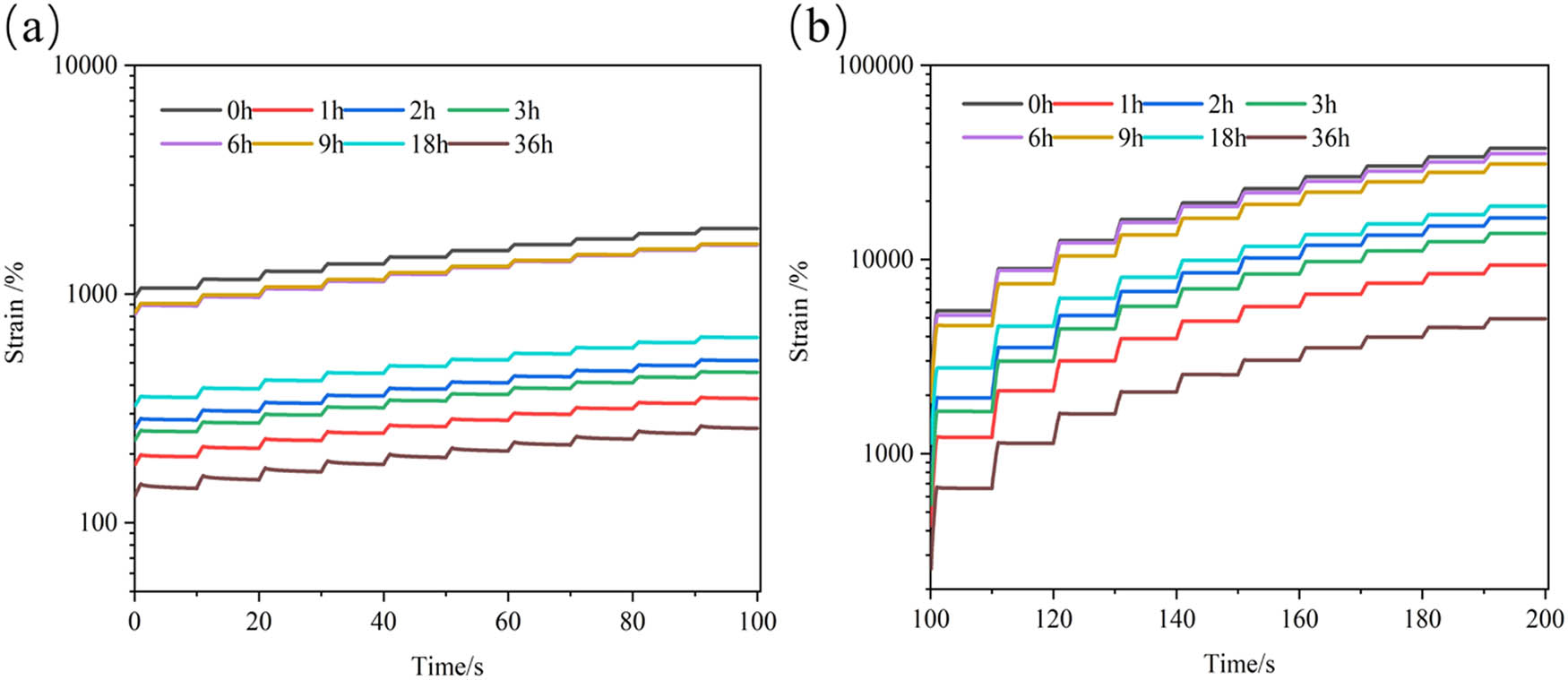
MSCR results of T770-modified asphalt enduring different thermal aging times: (a) 0.1 kPa and (b) 3.2 kPa.
Figure 8 shows the calculating results of the unrecoverable creep compliance J nr and the creep recovery rate R of T770-modified asphalt. Based on the comparison of the MSCR results of 0.1 and 3.2 kPa, it could be found that the unrecoverable creep compliance of the 3.2 kPa level results was larger than that of 0.1 kPa. The variation trend of unrecoverable creep compliance was similar under the two stress levels. The J nr of T770-modified asphalt was the largest and then decreased sharply when subjected to 1 h thermal aging. While the thermal aging process continued, the J nr of T770-modified asphalt increased from 1.7259 to 8.2648 following the extension of aging time. When the thermal aging time exceeded 6 h, the J nr of T770-modified asphalt began to be decreased, reduced from 8.2648 to 1.2997. This might be because that the addition of T770 increased the content of light components in asphalt, which reduced the high-temperature deformation resistance of asphalt and increased the viscous deformation, leading to an increase in J nr. Due to the volatilization of light components in the T770-modified asphalt, the asphaltene content increased and the resistance to permanent deformation enhanced. Furthermore, the viscous deformation was weakened, resulting in the sharp drop of the J nr of the T770-modified asphalt after aging for 1 h. During the thermal aging period between 1 and 6 h, the addition of T770 could enhance the thermal aging resistance of asphalt through blocking the increase in asphaltenes and other heavy components. In this process, the viscosity deformation of T770-modified asphalt increased and the J nr was increased. while the aging time was more than 6 h, the effect of T770 on the modified asphalt tended to be stable, but the heavy components increased with the deepening of aging degree, which led to the increase in elastic deformation and promoted the improvement of creep recovery performance. From Figure 8(b), it could be observed that the variation trend of R of T770-modified asphalt indicated that the creep recovery performance of T770-modified asphalt decreased first and then increased when subjected to thermal aging effect. However, at the stress level of 3.2 kPa, the R of T770-modified asphalt under different thermal aging time conditions was small and similar to that of aged matrix asphalt, indicating that high stress level would degrade the creep recovery performance of T770-modified asphalt and the high temperature deformation resistance was weakened.
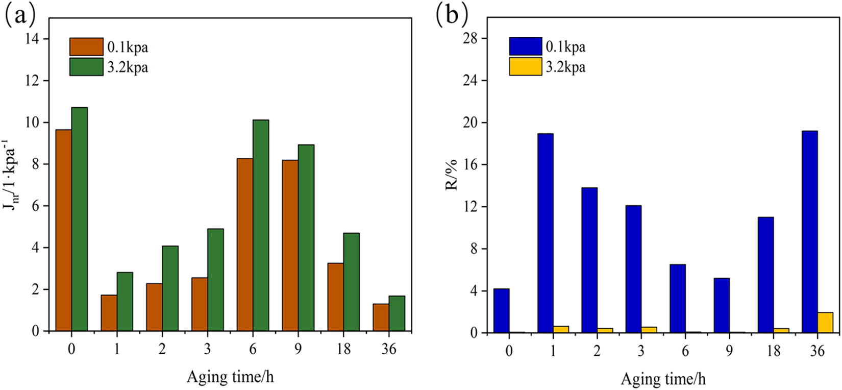
J nr and R of T770-modified asphalt enduring different thermal aging times: (a) J nr and (b) R.
3.2 AFM analysis of thermal-aged asphalt
3.2.1 Matrix asphalt
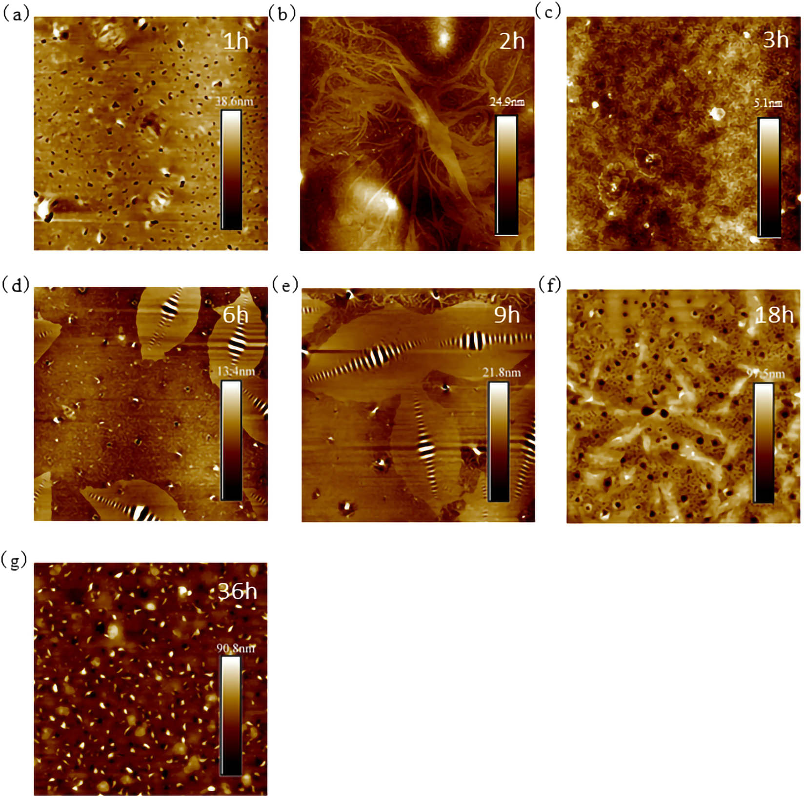
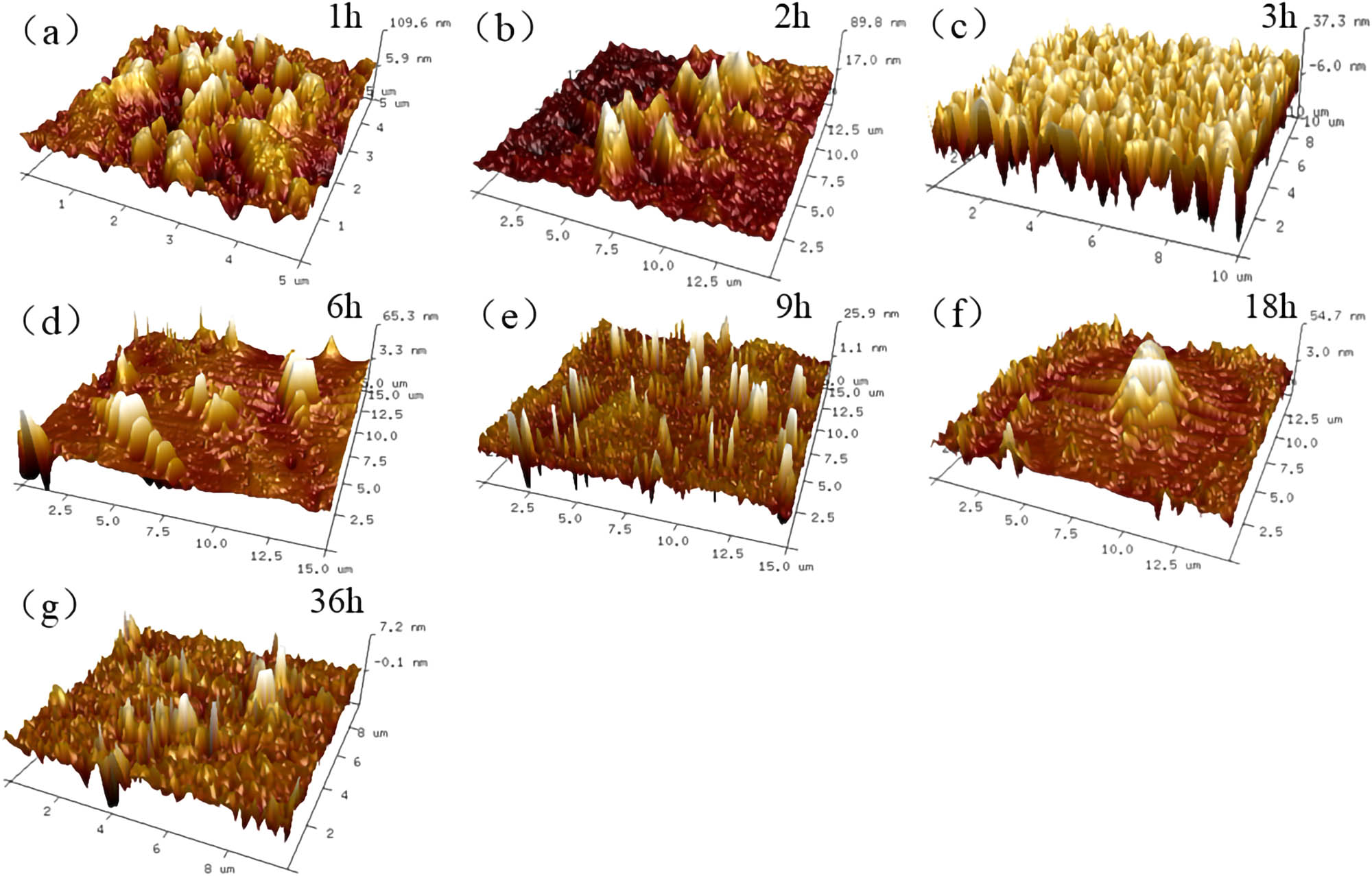
Figures 9–11 are the AFM characterization results of 70# asphalt under the conditions of different thermal aging times and magnifications. From 80 μm × 80 μm characterization results in Figure 9, it could be observed that after 1 h of thermal aging, considerable number of flocs appeared on the asphalt surface, which was connected with each other and covered the asphalt surface, and raised the surface roughness to a certain extent. After aging for 2 h, the flocculent structure on asphalt surface transformed into a number of independent areas, and the middle part of each area formed a dense area of about 10 nm in length, but the number of dense areas was less. When the aging time extended to 18 h, the bee structure emerged in the view field of AFM results, which was shown as alternating zone of internal light and dark. Finally, when the aging time reached 36 h, the typical structure of asphalt surface almost disappeared and the height of aged asphalt surface was around 9 nm, which indicated that the overall area was relatively flat without obvious characteristic structure.
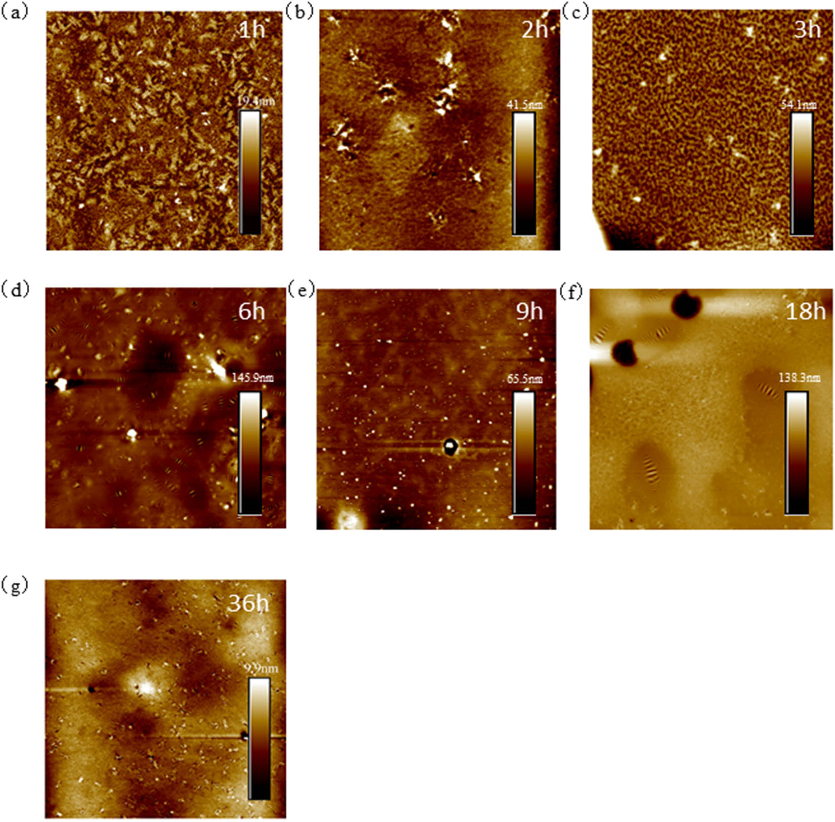
80 μm × 80 μm AFM results of 70# asphalt: (a) 1 h; (b) 2 h; (c) 3 h; (d) 6 h; (e) 9 h; (f) 18 h; and (g) 36 h.
30 μm × 30 μm AFM results of 70# asphalt: (a) 1 h; (b) 2 h; (c) 3 h; (d) 6 h; (e) 9 h; (f) 18 h; and (g) 36 h.
10 μm × 10 μm AFM results of 70# asphalt: (a) 1 h; (b) 2 h; (c) 3 h; (d) 6 h; (e) 9 h; (f) 18 h; and (g) 36 h.
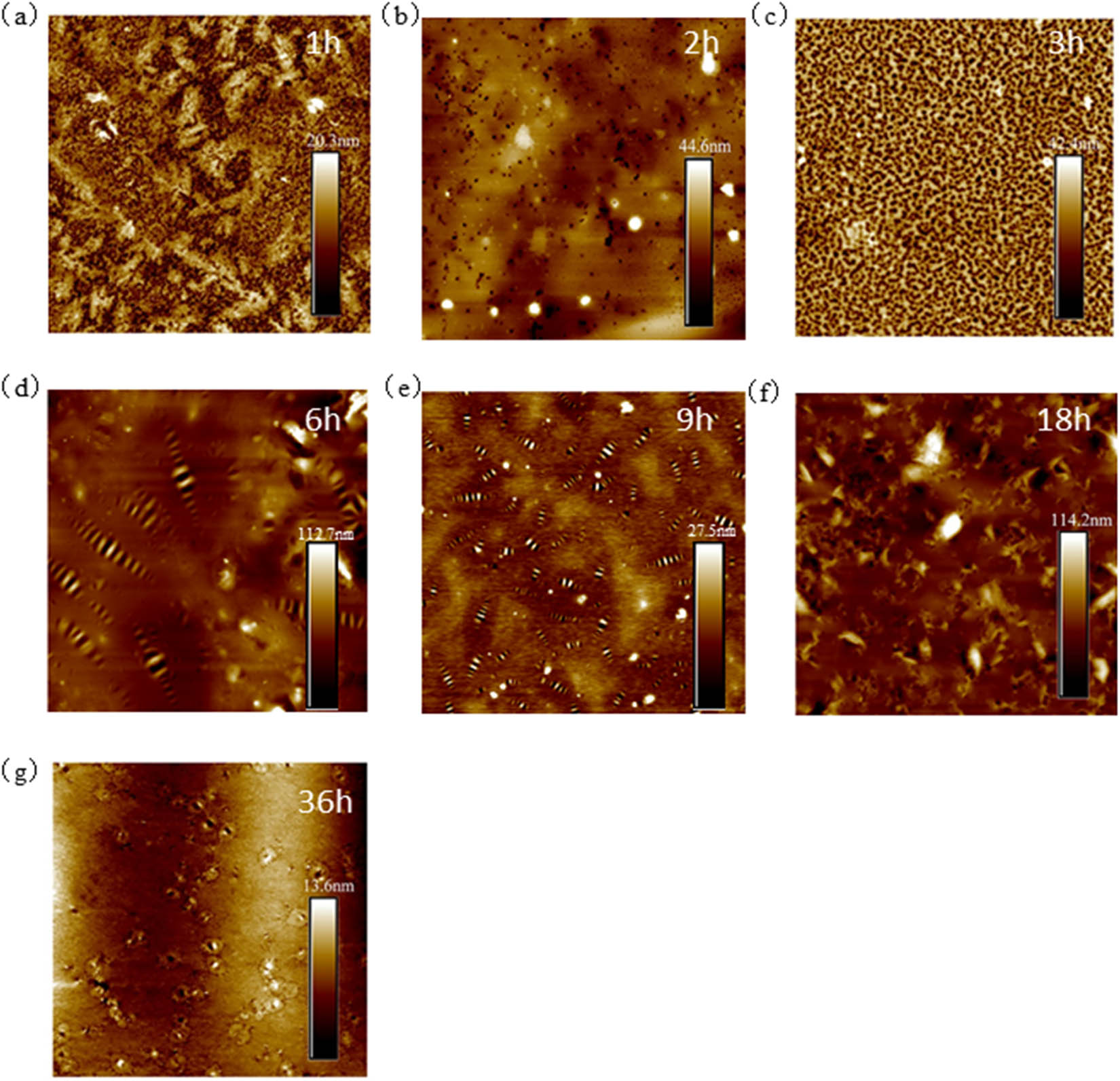
According to 30 μm × 30 μm AFM results (Figure 10), the flocculent structures were evenly dispersed on the asphalt surface and the average length was about 3.6 μm. In the aging process of 2–3 h, point-like morphology appeared in the interior of asphalt, and changed gradually from sparse to dense. When aging time was over 6 h, it could be clearly observed that there were number of bee structures on the surface of the aged asphalt. According to the phase transition theory, the dispersed phases on the asphalt surface began to be fused and gathered to the respective centers during thermal aging process, finally forming into multiple “independent units” (bee structure). The height of this structure was higher than that of other micro zones, and the internal position collapsed, resulting in the bee structure with height alternation [27]. The formation of bee structure might be due to the existence of strong polar asphaltene in the central position of micro zone and the surrounding colloid and wax components [28,29]. As the aging time extended to 9 h, the dispersion of bee structure inside the asphalt became more dense. When the thermal aging time reached 36 h, the average size of the bee structure decreased to 3.48 μm in the micro area of 30 μm × 30 μm, and the clarity of the high-low alternating morphology was obviously reduced. Based on this, during the gradual extension of thermal aging time, the asphalt surface experienced a “floc-dot structure-bee structure-incomplete bee structure” transition process, which also demonstrated that its surface roughness varied significantly throughout the thermal aging process.
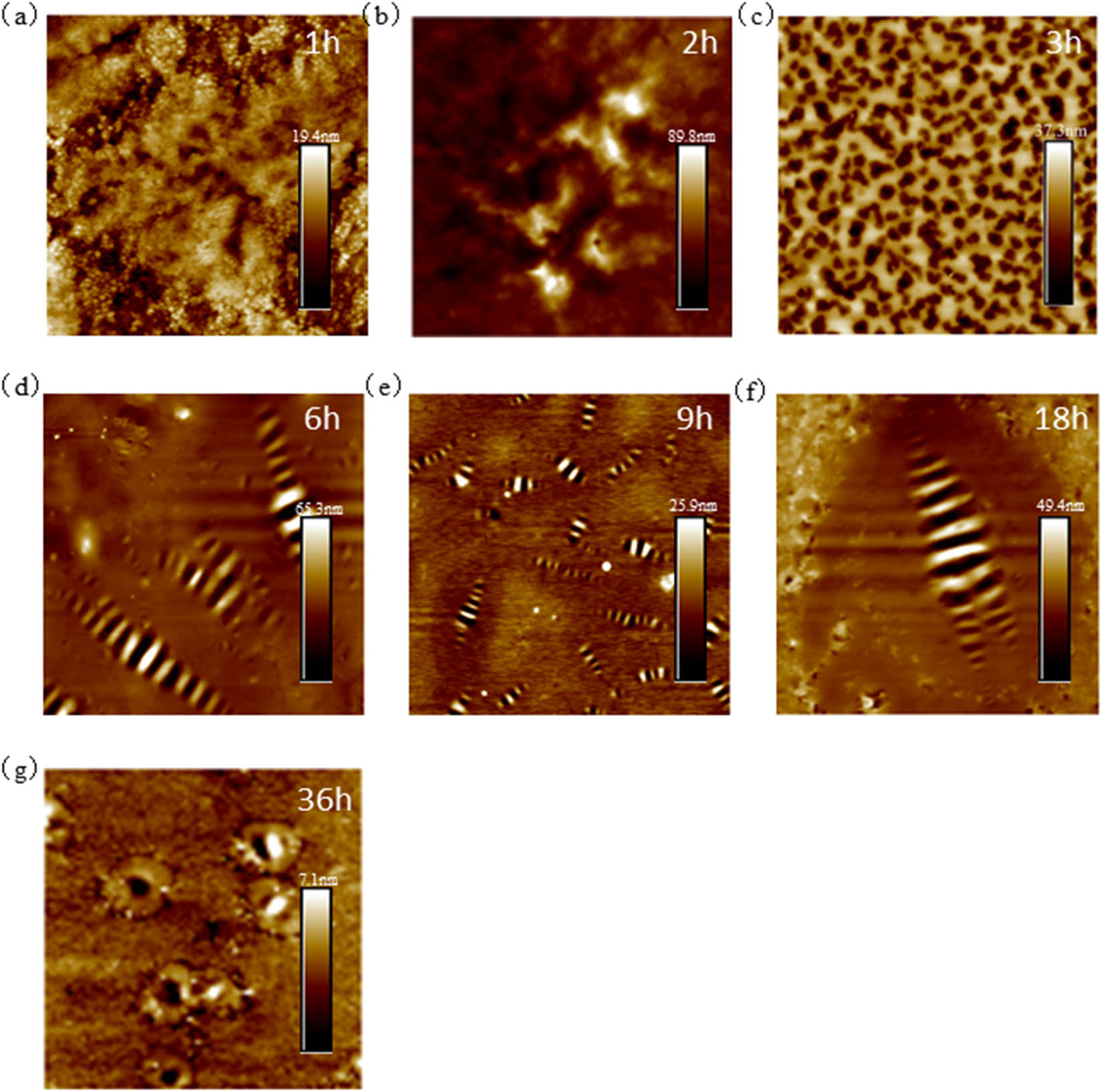
The scale of scanning zone continued to be enlarged by 10 μm × 10 μm as shown in Figure 11. The middle part of the asphalt surface after aging for 2 h showed a narrow and long bright area, which was different from the roughness of dark area. Meanwhile, the height of the color column was up to 89 nm, indicating that the bright structure was represented as convex shape in the local area of scanning zone. When the aging time reached 3 h, the black spots dispersed evenly on the asphalt surface, which could be inferred from height information that the black spots were small holes on asphalt surface. When the aging time reached 6 h, the bee structure appeared in the scanning zone. As the aging time extended, the number of bee structures increased significantly, while the size became smaller than that at 6 h. As thermal aging time extended to 18 h, there was only one bee structure existing in the scanning zone and it seemed that all the small bee structures had been merged to one large bee structure. Furthermore, the height of the typical structure at 18 h was twice as that of bee structure at 9 h. When the thermal aging time reached 36 h, the number and size of bee structure was significantly reduced, and the multi-structure composition between the bright and dark phases was transformed into a single bright and dark phase structure.
3.2.2 T770-modified asphalt
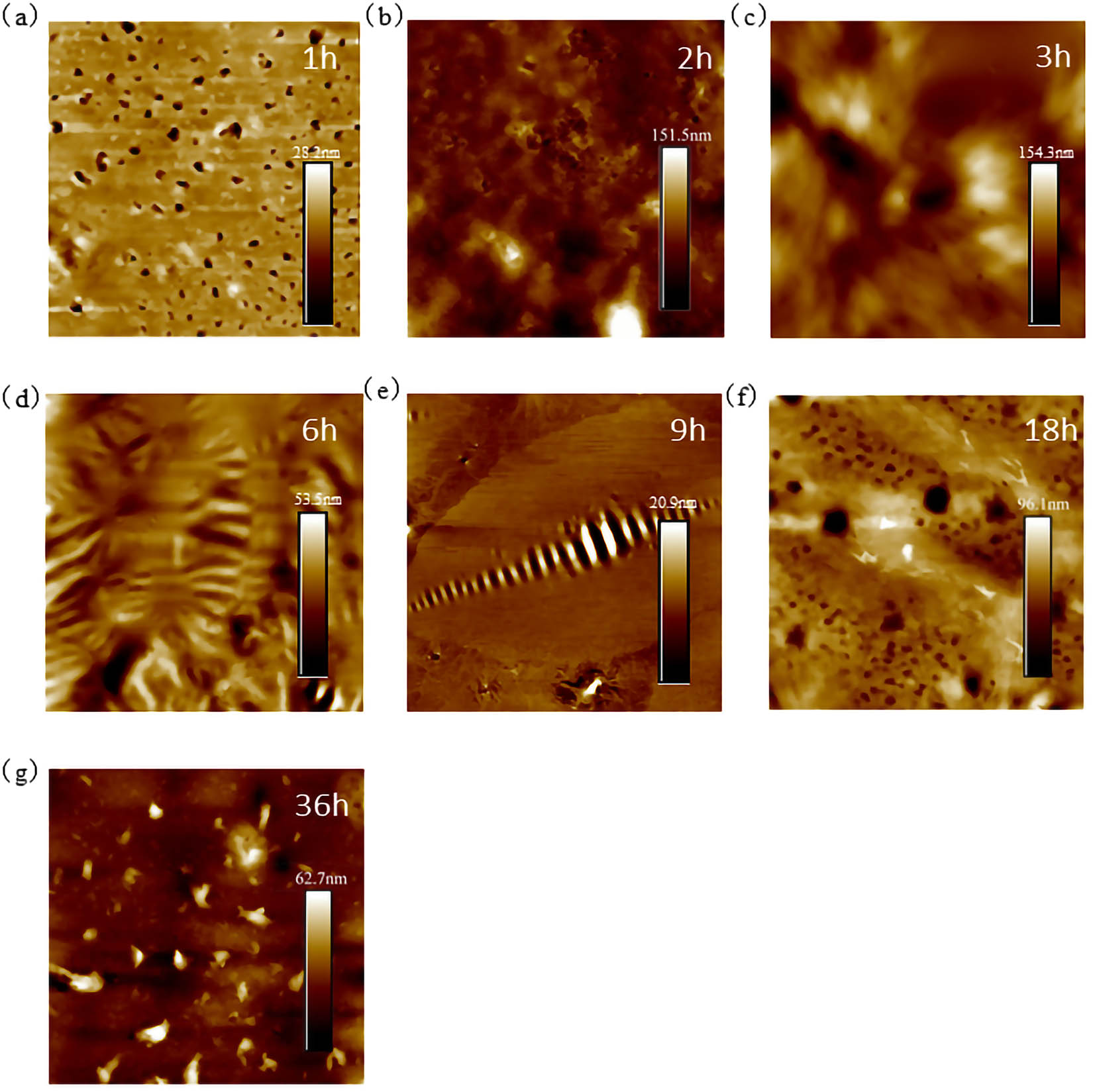
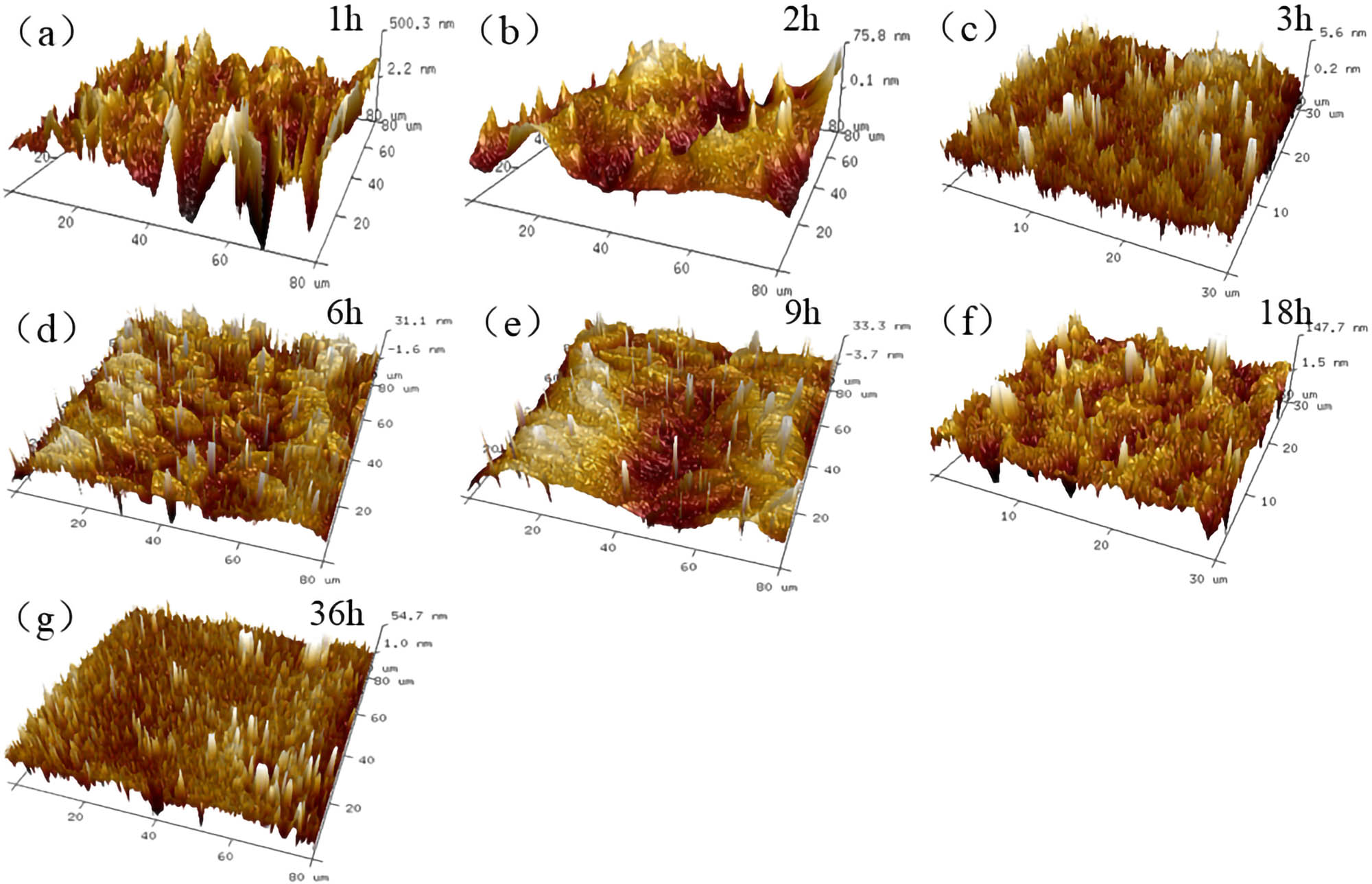
Figures 12–14 are the AFM characterization results of T770-modified asphalt under different aging times and magnifications. Different from 70# asphalt, there were some different micro structures appearing on the specimen surface when enduring thermal aging. For example, there were number of typical structures (similar to dendritic morphology) on the surface of asphalt after aging for 1–2 h as shown in Figure 12, and the distribution was relatively uniform. The length of dendritic structure ranged from 5 to 80 μm in the characterization area. Through analyzing the height data, the branch and rhizome positions of the dendritic structure were higher than the leaf position. The maximum height of the dendritic structure was approximately 500 nm, while the height around the rhizome decreased rapidly. After aging for 3 h, the dendritic structure gradually dissipated, and the maximum height decreased from the initial 500–5.7 nm, which indicated that the surface of T770-modified asphalt experienced a peak height change during the aging period from 0 to 3 h. After aging for 6 and 9 h, the surface of asphalt was filled with bee structures. However, compared with the results of 6 h, the number of bee structures decreased slightly at 9 h. Moreover, the single bee structure became larger, whose length increased from 15 μm to about 25 μm and height increased from 31.1 to 33.3 nm. The change in number and size of bee structure demonstrated that the 6 and 9 h aging times had obvious impact on the surface state of T770-modified asphalt, which might be related to the variation in chemical components in asphalt. When the thermal aging time reached 36 h, the bee structure on the asphalt surface almost disappeared, and the circular structure of about 4 μm in diameter appeared and the quantity increased sharply.
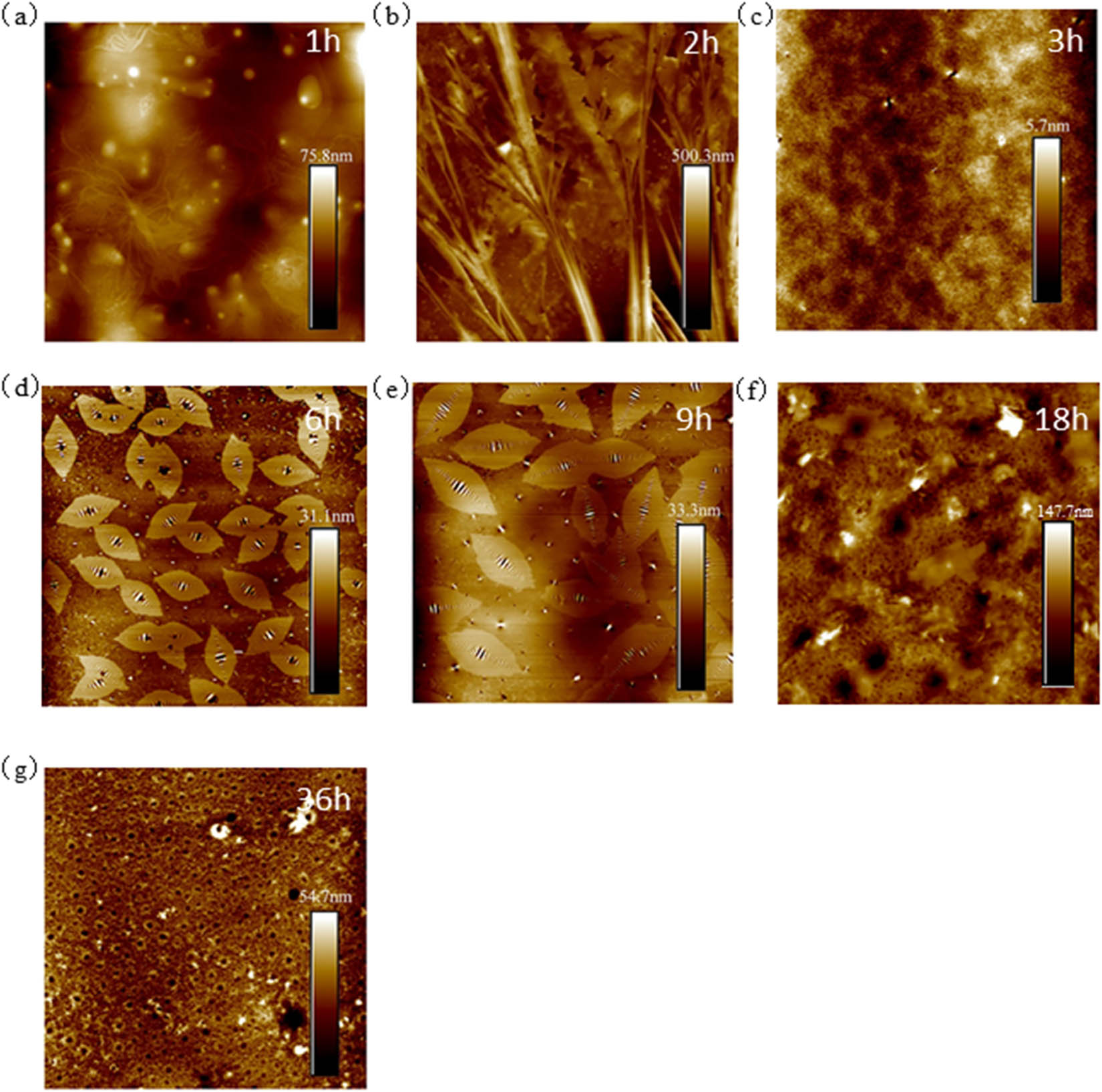
80 μm × 80 μm AFM results of T770-modified asphalt: (a) 1 h; (b) 2 h; (c) 3 h; (d) 6 h; (e) 9 h; (f) 18 h; and (g) 36 h.
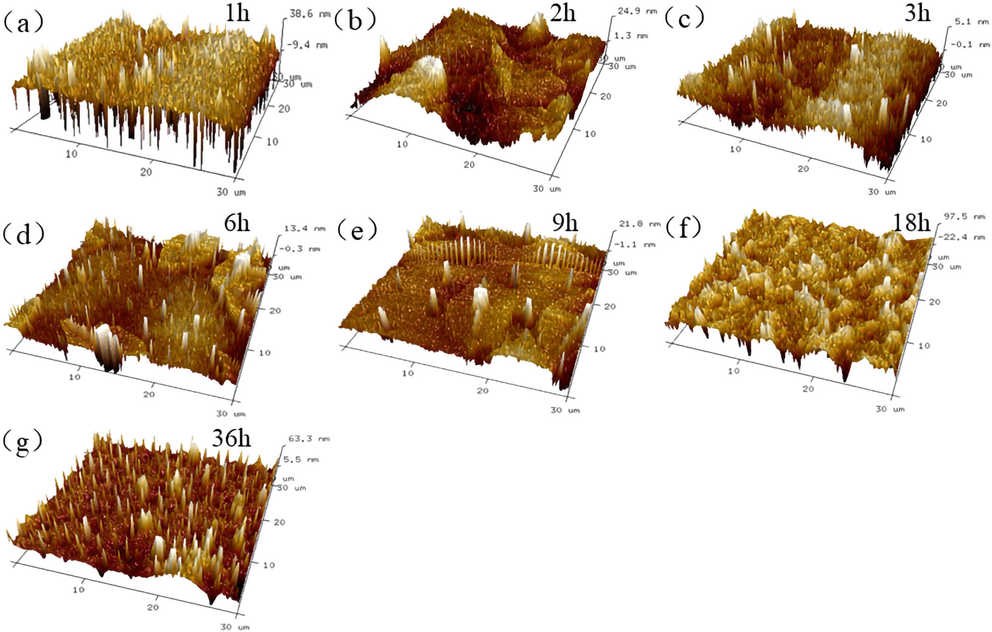
30 μm × 30 μm AFM results of T770-modified asphalt: (a) 1 h; (b) 2 h; (c) 3 h; (d) 6 h; (e) 9 h; (f) 18 h; and (g) 36 h.
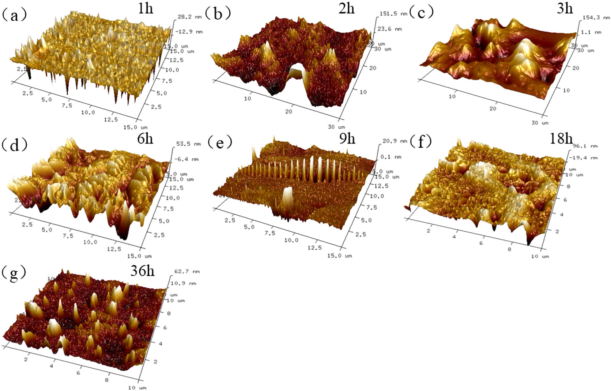
10 μm × 10 μm AFM results of T770-modified asphalt: (a) 1 h; (b) 2 h; (c) 3 h; (d) 6 h; (e) 9 h; (f) 18 h; and (g) 36 h.
In Figure 13 of 30 μm × 30 μm morphology, the AFM results of T770-modified asphalt represented tree structure in 2 h, which disappeared after aging for 3 h. At 3 h, the average length of tiny bright structures was about 1.75 μm. After thermal aging for 6 h, the bee structure appeared as the original bright spot and its initial length was about 9.4 μm. After 9 h of thermal aging, the bee structures began to connect with each other from the original dispersed layout, and the average length increased to 14.2 μm, which indicated that there was a mutual fusion behavior of bee structures in the process of thermal aging. As the aging time progressed to 18 h, the bee structure on the surface of modified asphalt disappeared, replaced by a white strip of about 6.4 μm in length, which was surrounded by black spots when amplified to 10 μm × 10 μm (Figure 14). After 36 h aging, the size of bee structures reached the lowest value, but the number increased sharply. Furthermore, the light and dark alternate features of bee structure were more obvious.
3.3 Three-dimensional surface reconstruction of thermal-aged asphalt materials
3.3.1 Matrix asphalt
The 3D reconstructed surface morphology of thermal-aged matrix asphalt is shown in Figure 15. It could be observed from Figure 15 that the overall roughness of asphalt surface became relatively small during the thermal aging period from 1 to 3 h. The height distributed as pinpoint variation at 1 h and the asphalt surface was quite flat. After aging for 2 h, the surface roughness of the asphalt was reduced, and the height was low in the surrounding and high in the middle. The height of the typical structure in the middle was significantly larger than that in the surrounding, which was also in accordance with the AFM 2D analysis results. However, there were more regional points of height variation on the asphalt surface at 6 and 9 h, and the surface of asphalt turned to be relatively flat after aging for 18 h. After aging for 36 h, the height point was distributed in a wavy shape, whose height was large on both sides and small in the middle, but the average height of asphalt surface decreased significantly.
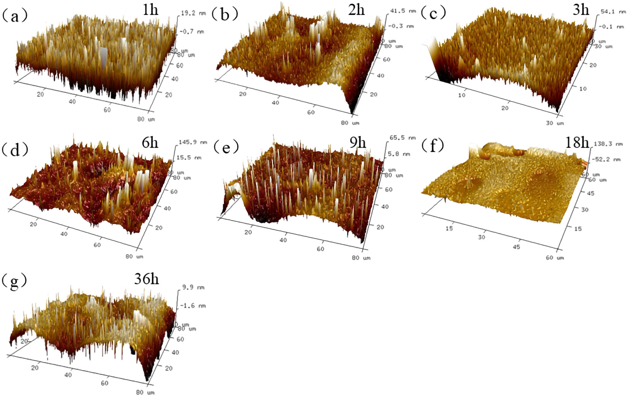
80 μm × 80 μm 3D reconstructed results of 70# asphalt: (a) 1 h; (b) 2 h; (c) 3 h; (d) 6 h; (e) 9 h; (f) 18 h; and (g) 36 h.
According to Figure 16 (30 μm × 30 μm), the height variation was evenly distributed and the heights of different testing points were similar at 1 h of thermal aging. After aging for 2 h, the surface height of the asphalt fluctuates significantly. In the relevant 2D figure, it could be observed that many bright positions were mainly located in the middle concave, and the height was slightly larger than that of the surrounding structures. When aging time reached 3 h, the surface of asphalt became flat again and the height was evenly distributed and there was no obvious typical structures. As aging time extended from 6 to 18 h, the overall fluctuation of asphalt surface was more obvious and the surface roughness increased significantly. When the thermal aging time reached 36 h, the surface height of asphalt tended to be flat, whose height distribution was presented as wave pattern. As shown in Figure 17, the surface height of the structure after aging for 2 h was about 89.9 nm. The surface height of asphalt decreased gradually, but the overall roughness increased after aging for 3 and 6 h. At the aging time of 18 h, the bee structure on the 2D results demonstrated in 3D image that the middle position between the two peaks (bright zone) was presented as low height site (dark zone).
30 μm × 30 μm 3D reconstructed results of 70# asphalt: (a) 1 h; (b) 2 h; (c) 3 h; (d) 6 h; (e) 9 h; (f) 18 h; and (g) 36 h.
10 μm × 10 μm 3D reconstructed results of 70# asphalt: (a) 1 h; (b) 2 h; (c) 3 h; (d) 6 h; (e) 9 h; (f) 18 h; and (g) 36 h.
3.3.2 T770-modified asphalt
The 3D reconstructed surface morphology of thermal-aged T770-modified asphalt is shown in Figure 18. The surface roughness of T770-modified asphalt changed obviously when aged for 1 h, and the maximum height of modified asphalt surface was about 500 nm, which was corresponding to the rhizome part of the dendritic structure. After 2 h of thermal aging treatment, dendritic structure on the surface of the modified asphalt disappeared gradually and the height distribution tended to be stable. After aging for 6 h, the asphalt surface was covered with the bee structures and there was an obvious height change in the existing bee structure area, which varied gradually from high distribution in the middle to low distribution on both the sides, and the highest height was about 31.1 nm. When the thermal aging time extended to 9 h, the roughness undulation of specimen surface became larger. The number of bee structure decreased, while the size increased. At aging of 36 h, no special micro-structures appeared on the surface of the T770-modified asphalt, and only some zones underwent height changes.
80 μm × 80 μm 3D reconstructed results of T770-modified asphalt: (a) 1 h; (b) 2 h; (c) 3 h; (d) 6 h; (e) 9 h; (f) 18 h; and (g) 36 h.
Figure 19 of the 30 μm × 30 μm AFM results shows that the point height variation in T770-modified asphalt surface was significantly present after thermal aging for 1 h, but no typical structure appeared on asphalt surface. After aging for 2 h, considerable needle-like height points were fused into the convex structure of large volume and the height became larger, up to 151.5 nm. According to the 3D images of 6 and 9 h, the number of bee structures decreased relatively. Following the extension of thermal aging time, T770-modified asphalt surface bee structures gradually disappeared and the surface height further increased.
30 μm × 30 μm 3D reconstructed results of T770-modified asphalt: (a) 1 h; (b) 2 h; (c) 3 h; (d) 6 h; (e) 9 h; (f) 18 h; and (g) 36 h.
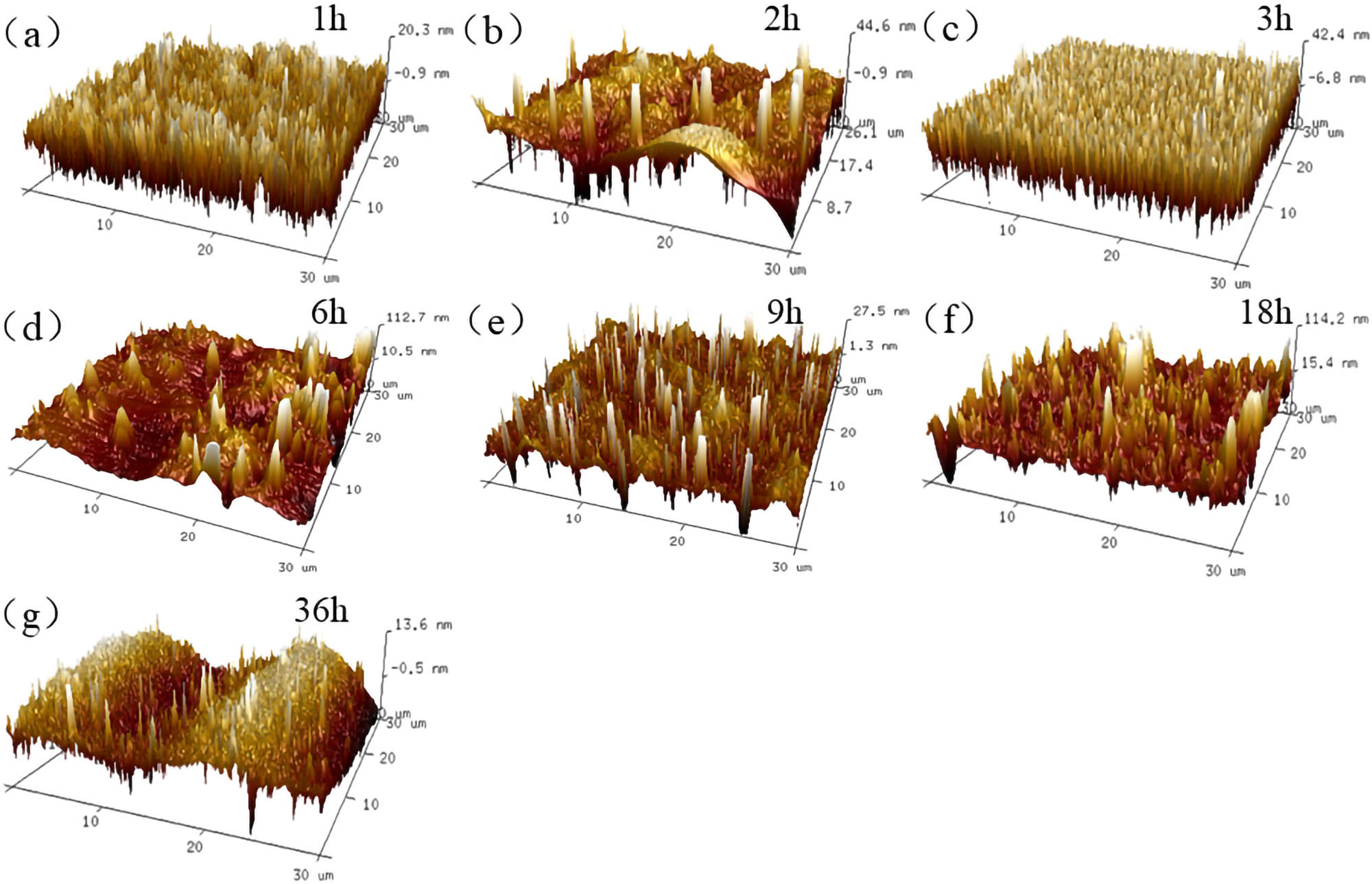
From the 10 μm × 10 μm results of Figure 20, it could be analyzed that the height distribution of amplified zone was relatively flat at 1 h of aged time. Only part of scanning areas has protrusions, while the roughness change in surface concavity was complicated. After aging for 2 h, the undulation degree of modified asphalt surface increased significantly, and the higher position was mainly distributed in the edge area. The utmost height of the scanning area was 151.5 nm, and the surface roughness was further increased. When thermal aging time reached 3 h, the peak height of the modified asphalt surface increased to 154.3 nm, and the roughness continued to increase. The surface structure height began decreasing relatively at 6 h, and the highest area height reduced to 53.5 nm, about half of that at 3 h. The linear height variation appeared on the modified asphalt surface at 9 h. The height change increased evenly from both ends to the middle, demonstrating the alternating change in height, which referred to the bee structure. As aging time moved to 18 h, the surface roughness of asphalt increased and the highest peak was 96.1 nm. Furthermore, the appearance of bee structure was no longer clear. After 36 h, a number of independent vertical block structures appeared on the modified asphalt surface and the roughness increased.
10 μm × 10 μm 3D reconstructed results of T770-modified asphalt: (a) 1 h; (b) 2 h; (c) 3 h; (d) 6 h; (e) 9 h; (f) 18 h; and (g) 36 h.
3.3.3 Surface roughness analysis of thermal-aged asphalt material
In order to clarify the difference in surface roughness between 70# asphalt and T770-modified asphalt at different aging times, the roughness data were processed and obtained from the AFM characterization results of 30 μm × 30 μm. The evaluating indices mainly included the difference in three-dimensional surface area and two-dimensional projected surface area (ISAD), height mean square deviation (Rq), and height deviation (Ra). The calculated evaluating indices are shown in Table 3.
Surface roughness of 70# asphalt and T770-modified asphalt
| Thermal aging time (h) | 70# asphalt | T770-modified asphalt | ||||
|---|---|---|---|---|---|---|
| ISAD (%) | Rq (nm) | Ra (nm) | ISAD (%) | Rq (nm) | Ra (nm) | |
| 1 | 0.181 | 6.57 | 5.29 | 0.383 | 11.3 | 7.42 |
| 2 | 0.160 | 11.10 | 7.44 | 0.242 | 29.1 | 19.9 |
| 3 | 1.100 | 16.20 | 13.50 | 0.003 | 1.65 | 1.31 |
| 6 | 0.233 | 8.61 | 4.10 | 0.037 | 3.86 | 2.49 |
| 9 | 0.356 | 12.10 | 9.00 | 0.073 | 5.38 | 3.26 |
| 18 | 0.336 | 22.50 | 15.50 | 1.16 | 28.6 | 19.8 |
| 36 | 0.014 | 4.30 | 3.56 | 0.565 | 18.1 | 12.2 |
The data in Table 3 shows that the surface roughness Rq value of 70# asphalt presented the fluctuation trend of “increasing-decreasing-increasing-decreasing”. When the aging time reached 18 h, the roughness reached the maximum value of about 22.5 nm and then decreased to the minimum value of 4.3 nm at 36 h. The change trend of Ra value was basically consistent with that of Rq, indicating that the surface roughness of 70# asphalt was the largest after aging for 18 h. When the aging time continued being extended, the surface roughness of asphalt decreased to the minimum. This might be because the continuous high temperature state induced the aggregation and nucleation of asphaltenes, wax fractions, and other components of asphalt. As the thermal aging time continued to be increased, the properties of nucleation components were unstable and diffused, which led to the change trend of surface roughness. For T770-modified asphalt, the variation trend of roughness indices Rq and Ra was basically the same as that of 70# asphalt. In the process of thermal aging, the roughness of T770-modified asphalt decreased first and then increased. The roughness reached the maximum at 18 h of aging time, and the maximum difference values of roughness indices were 1.157% and 27.45 and 18.59 nm, respectively. The variation amplitude of surface fluctuation was larger than that of 70# asphalt in the whole process of thermal aging, indicating that the addition of T770 would aggravate the surface roughness variation in thermal-aged asphalt to a certain extent, but the large variation in roughness might not be necessarily connected to the attenuation of asphalt performance. Since the surface of asphalt was not smooth when adhered to the aggregate, the higher the roughness index was, the better adhesion between asphalt and aggregate might be [30].
3.4 Typical structure identification of thermal-aged asphalt
3.4.1 Cluster structure
Figure 21 shows the morphology and roughness analysis results of 1 h thermal-aged asphalt. From Figure 21(a) and (b), after 1 h of aging, the asphalt surface was filled with cluster structures of about 10 μm in length, whose heights were generally higher than that of the surrounding asphalt surface. Four cluster structures in scanning zone were named as I–IV and the geometric characteristics were calculated, as shown in Figure 21(c)–(f). Figure 21(c)–(f) shows that the heights of structures II and III are around 80 nm, while the heights of structures I and IV are above 100 nm. Regarding structure I, three height peaks existed and the high peak of 104 nm was surround by two height peaks of about 80 nm. Furthermore, there was also a height valley and its height was at least about −39.7 nm, which indicated that the cluster structure consisted of several height peaks and valleys. The II–IV cluster structures also included at least two height peaks and height valleys, which concluded that the surface of thermal-aged asphalt was full of bumps and holes led by the height variation. The appearance of cluster structures indicated that the thermal aging effect could promote significant variation in asphalt surface at the start of aging treatment.
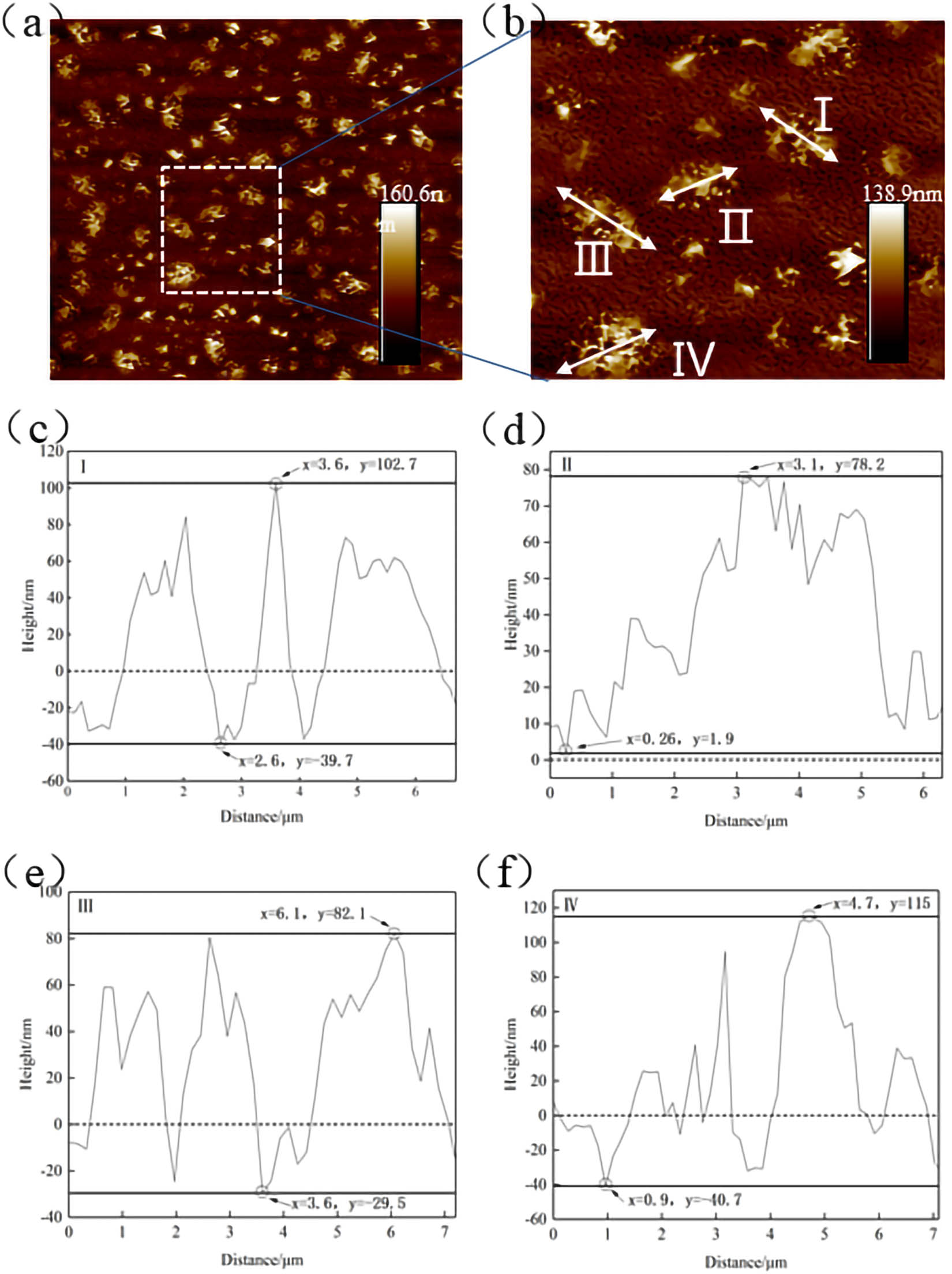
Morphology and roughness analysis results of cluster structure: (a) scanning zone; (b) selected cluster structure; (c) cluster structure I; (d) cluster structure II; (e) cluster structure III; and (f) cluster structure IV.
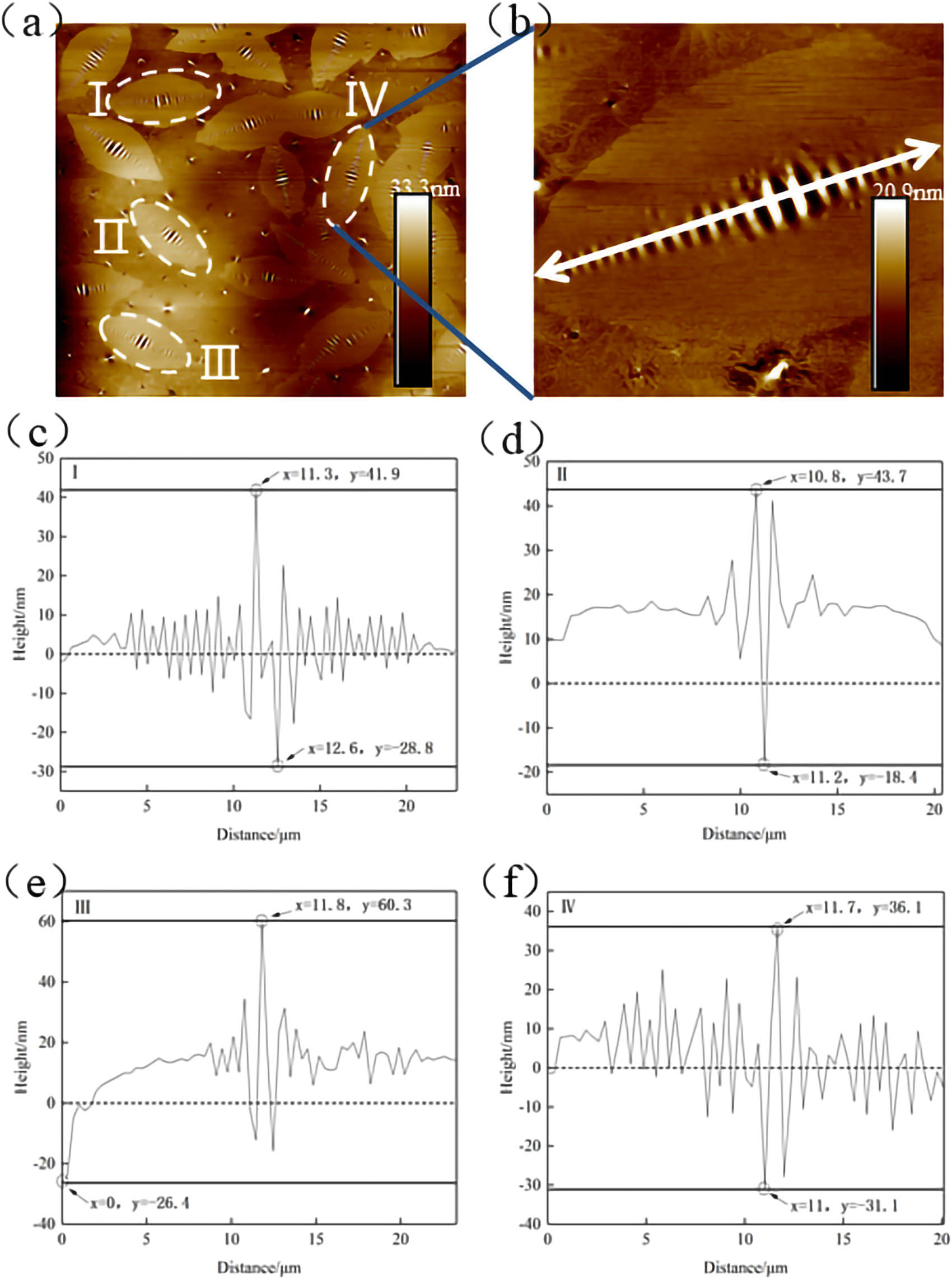
Roughness indices could be obtained by roughness processing of the above four structures, as shown in Figure 22. The height difference between the highest peak and lowest valley of structure IV was 155.7 nm, which was higher than that of the other three structures. In addition, due to the existence of “0” plane, several height valleys in the four structures were very deep, resulting in the larger roughness of cluster structure IV than that of the other three structures. Compared with cluster structure II of the lowest roughness value, Rq and Ra of cluster structure IV were increased by 11 and 8.8 nm, respectively. The roughness differences of the other two clusters were not obvious, within 2 nm.
Roughness comparison between different clustered structures.
3.4.2 Bee structure
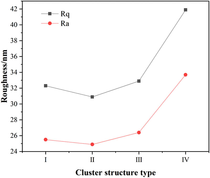
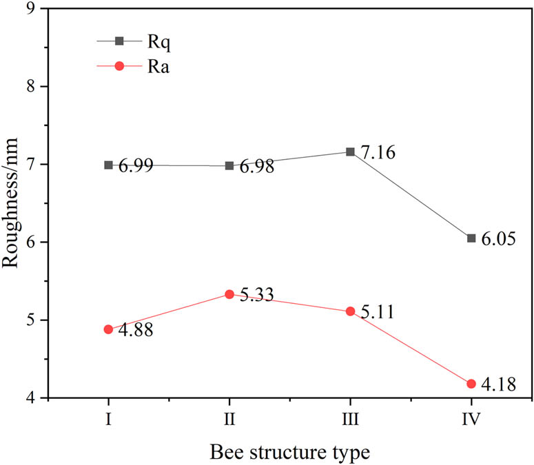
Figure 23 shows the morphology and roughness analysis results of thermal-aged T770-modified asphalt. From Figure 23(a), it could be observed that after 9 h of thermal aging treatment, number of bee structures of obvious morphology and uniform distribution appeared on the surface of T770-modified asphalt. The height feature of bee structure on the surface of T770-modified asphalt was the height alternation between high and low, which could be observed in Figure 23(c)–(f). Furthermore, the bee structure showed obvious three-phase state, as well as the continuous phase and dispersed phase accompanied by it. Currently, there were two main viewpoints explaining the formation process of bee structure. The first explanation was that the bee structure was formed by crystallization and nucleation of wax composition. The other supposed that the nucleation of asphaltene led to the appearance of bee structure. However, no matter what the forming mechanism was, this structure would have certain impact on the adhesion between asphalt and aggregate [31].
Morphology and roughness analysis results of bee structure: (a) scanning zone; (b) selected bee structure; (c) bee structure I; (d) bee structure II; (e) bee structure III; and (f) bee structure IV.
Figure 23(c)–(f) shows the roughness curve of selected bee structures on the surface of thermal-aged T770-modified asphalt. According to Figure 23(c)–(f), it could be observed easily that the height of bee structure alternated in high position (peak) and low position (valley). For bee structure I–IV, the peak height values were 41.9, 43.7, 60.3, and 36.1 nm, respectively. The amplitude between the adjacent peaks and valleys at the center position was more than 60 nm, and there were obvious differences in the vertical height distribution. The alternated distributions of height in structures I and IV were much more complex than that in structures II and III. Through calculation, it could be concluded that the width of the peak and valley was about 0.5–0.6 μm, and the average spacing between the peak and valley was about 0.3 μm (wavelength). Although the difference between the spacing was not obvious, in fact, the wavelength and the amplitude length of the bee structure were different by an order of magnitude. In addition, relevant studies also proposed that the bright part of the bee structure was softer than the dark part [24,26], and the outer part of the bee structure was surrounded by oil of relatively flat height. According to the composition of the bee structure, the modulus was slightly higher at the flat area by measuring the force-curve, which was mainly due to that the asphaltene belonged to the heavy component that had large molecular weight, and the smaller molecular weight components such as hydrocarbon chains were filled in the dark part of the bee structure [32] (Figure 24).
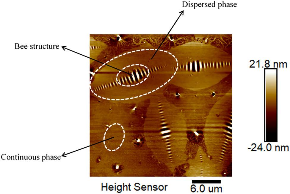
Bee structure analysis of T770-modified asphalt.
The roughness indices were obtained by data processing of the bee structures I–IV, as shown in Figure 25. The Rq and Ra roughness values of the bee structure IV were lower than that of the other three structures. The maximum peak height of bee structure IV was 36.1 nm and the minimum valley height was 31.1 nm. Compared with the other three structures, the peaks and valleys of structure IV were evenly distributed at both ends of the “0” plane, so that the roughness value was the lowest among the four structures. The Rq value of structure III was the highest and the difference between the peak and the valley point was 86.7 nm. However, the lowest height point was not included in the area of the bee structure, resulting in the most obvious height difference compared with the other three structures. Moreover, the surface height distributions of structures II and III were mostly above the plane and only some valleys were below the plane. Regarding the roughness index, the Ra values of structures II and III were higher than that of the other two structures.
Roughness comparison between different bee structures.
3.4.3 Dendritic structure
Figure 26 shows the morphology and roughness analysis results of thermal-aged T770-modified asphalt. Structures I and II could be identified from Figure 26(a) and (b), whose morphology was similar to the tree roots and branches, so named as dendritic structures. The formation of dendritic structure might be caused by the small-scale dispersion and fusion of T770-modifier in asphalt under the heat treatment. By defining the “0” boundary, it could be observed that the height difference between the upper and lower parts of structure I was about 6.5 nm, and the width difference was about 3.5 nm. For the structure II, the “trunk” was narrow and long, existing as waviness in the length direction. The overall height of structure II was above the “0” position and the maximum and minimum heights were 13.9 and −2.6 nm, respectively. Furthermore, there was a “valley” around the maximum peak, as shown in Figure 26(c) and (d). The height difference between the adjacent “valley” structures was about 11–12 nm, and the width was about 3.5 μm, showing the long flat shape.
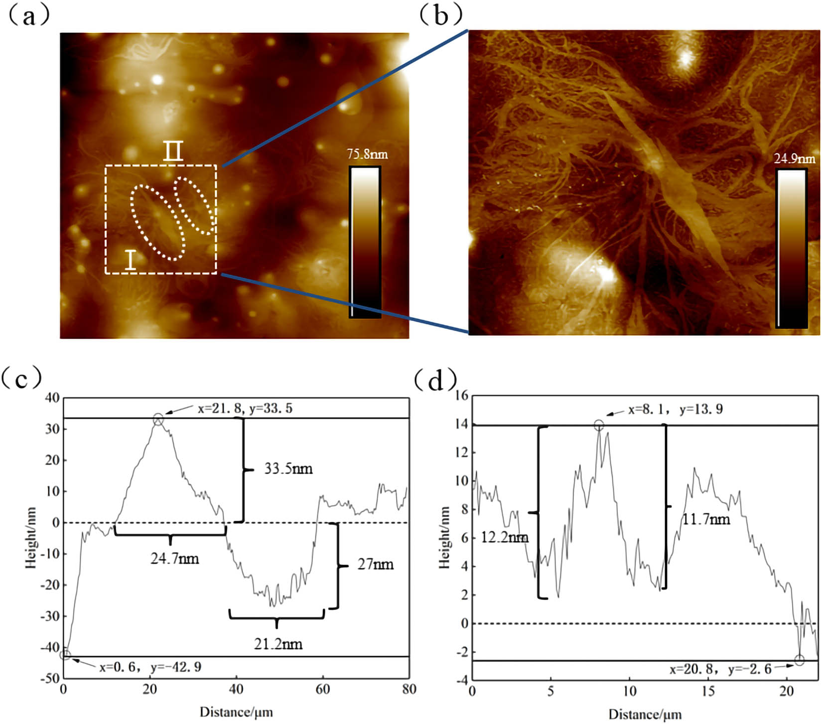
Morphology and roughness analysis results of dendritic structure: (a) scanning zone; (b) selected dendritic structure; (c) dendritic structure I; and (d) dendritic structure II.
4 Conclusion
In this study, T770 HALS was selected as anti-aging agent to prepare the modified asphalt. The impact of thermal aging on the rheological properties of T770-modified asphalt was investigated using DSR test of frequency sweep and MSCR test. The surface roughness variation in T770-modified asphalt was characterized by using AFM throughout the thermal aging process. The conclusions are shown as follows:
With the extension of thermal aging time, the G* and |G*|/sin δ of T770-modified asphalt decreased gradually when the aging time was less than 6 h. After aging for more than 6 h, the G* and |G*|/sin δ of T770-modified asphalt increased linearly and the slope was close to 1.
The J nr of T770-modified asphalt increased from 1.7259 to 8.2648 following the extension of aging time. When the thermal aging time exceeded 6 h, the J nr of T770-modified asphalt was reduced from 8.2648 to 1.2997, which might be because that the addition of T770 increased the content of light components in asphalt and reduced the high-temperature deformation resistance of asphalt.
The variation amplitude of surface fluctuation was larger than that of 70# asphalt in the whole process of thermal aging, indicating that the addition of T770 would aggravate the surface roughness variation in thermal-aged asphalt to a certain extent, but the large variation in roughness might not be necessarily connected to the attenuation of asphalt performance.
Three typical structures, cluster structure, bee structure, and dendritic structure, were identified through processing the rough data of AFM results. The roughness indices demonstrated the variation effect of thermal aging on T770-modified asphalt following the extension of aging time.
This study focused on the effect of thermal aging on T770-modified asphalt based on AFM and DSR. Future study will perform relevant experiment of chemical component variation to explore the thermal aging effect on the chemical constitution of HALS-modified asphalt.
-
Funding information: This study describes the research activities mainly requested and sponsored by Shanxi Transportation Holdings Group Co., Ltd. Technical Project under Grant No. 19-JKKJ-20, Foundation Committee of Basic and Applied Basic Research of Guangdong Province Youth Foundation Project under Grant No. 2019A1515110348, and Guangdong Provincial Natural Science Foundation Project (Grant No.2019A1515011397). That sponsorship and interest are gratefully acknowledged.
-
Author contributions: All authors have accepted responsibility for the entire content of this manuscript and approved its submission.
-
Conflict of interest: The authors state no conflict of interest.
References
[1] Yu H, Zhu Z, Leng Z, Wu C, Zhang Z, Wang D, et al. Effect of mixing sequence on asphalt mixtures containing waste tire rubber and warm mix surfactants. J Clean Prod. 2020;246:119008.10.1016/j.jclepro.2019.119008Search in Google Scholar
[2] Jin J, Liu S, Gao Y, Liu R, Huang W, Wang L, et al. Fabrication of cooling asphalt pavement by novel material and its thermodynamics model. Constr Build Mater. 2021;272:121930.10.1016/j.conbuildmat.2020.121930Search in Google Scholar
[3] Zhou X, Zhang X, Xu S, Wu S, Liu Q, Fan Z. Evaluation of thermo-mechanical properties of graphene/carbon-nanotubes modified asphalt with molecular simulation. Mol Simul. 2017;43(4):312–9.10.1080/08927022.2016.1274985Search in Google Scholar
[4] Luo M. Study of asphalt performance impact with ultraviolet aging. IOP Conference Series: Materials Science and Engineering. Vol. 231, Issue 1. Singapore: IOP Publishing; 2017 Sept. p. 012107.10.1088/1757-899X/231/1/012107Search in Google Scholar
[5] Wu S, Ye Y, Li Y, Li C, Song W, Li H, et al. The effect of UV irradiation on the chemical structure, mechanical and self-healing properties of asphalt mixture. Materials. 2019;12(15):2424.10.3390/ma12152424Search in Google Scholar PubMed PubMed Central
[6] Ye F, Sun DQ, Huang P, Zhu JP, Zhou ZD. Analysis of asphalt photooxidation aging property under intensive ultraviolet. China J Highw Transp. 2006;19(6):35–8 (in Chinese).Search in Google Scholar
[7] Tan Y, Wang J, Feng Z, Zhou X, Xu H. Ultraviolet aging mechanism of asphalt binder. China J Highw Transp. 2008;21(1):19–24 (in Chinese).Search in Google Scholar
[8] Yu H, Yao D, Qian G, Cai J, Gong X, Cheng L. Effect of ultraviolet aging on dynamic mechanical properties of SBS modified asphalt mortar. Constr Build Mater. 2021;281:122328.10.1016/j.conbuildmat.2021.122328Search in Google Scholar
[9] Jia H, Wang H, Chen W. The combination effect of hindered amine light stabilizers with UV absorbers on the radiation resistance of polypropylene. Radiat Phys Chem. 2007;76(7):1179–88.10.1016/j.radphyschem.2006.12.008Search in Google Scholar
[10] Zhang Q, Leroux F, Tang P, Li D, Feng Y. Low molecular weight hindered amine light stabilizers (HALS) intercalated MgAl-Layered double hydroxides: Preparation and anti-aging performance in polypropylene nanocomposites. Polym Degrad Stab. 2018;154:55–61.10.1016/j.polymdegradstab.2018.05.027Search in Google Scholar
[11] Niu D, Xie X, Zhang Z, Niu Y, Yang Z. Influence of binary waste mixtures on road performance of asphalt and asphalt mixture. J Clean Prod. 2021;298:126842.10.1016/j.jclepro.2021.126842Search in Google Scholar
[12] Xiao F, Amirkhanian SN, Karakouzian M, Khalili M. Rheology evaluations of WMA binders using ultraviolet and PAV aging procedures. Constr Build Mater. 2015;79:56–64.10.1016/j.conbuildmat.2015.01.046Search in Google Scholar
[13] Zhang H, Chen Z, Xu G, Shi C. Evaluation of aging behaviors of asphalt binders through different rheological indices. Fuel. 2018;221:78–88.10.1016/j.fuel.2018.02.087Search in Google Scholar
[14] Li Y, Wu S, Liu Q, Xie J, Li H, Dai Y, et al. Aging effects of ultraviolet lights with same dominant wavelength and different wavelength ranges on a hydrocarbon-based polymer (asphalt). Polym Test. 2019;75:64–75.10.1016/j.polymertesting.2019.01.025Search in Google Scholar
[15] Zeng W, Wu S, Wen J, Chen Z. The temperature effects in aging index of asphalt during UV aging process. Constr Build Mater. 2015;93:1125–31.10.1016/j.conbuildmat.2015.05.022Search in Google Scholar
[16] Zeng W, Wu S, Pang L, Chen H, Hu J, Sun Y, et al. Research on Ultra Violet (UV) aging depth of asphalts. Constr Build Mater. 2018;160:620–7.10.1016/j.conbuildmat.2017.11.047Search in Google Scholar
[17] Xu S, Yu J, Ke Y, Xue L, Hu C. Preparation and anti-ultraviolet aging performance of organic layered double hydroxides/bitumen composites. J Wuhan Univ Technol Mater Sci Ed. 2019;34(4):979–86.10.1007/s11595-019-2147-2Search in Google Scholar
[18] Dai Z, Shen J, Shi P, Zhu H, Li X. Nano-sized morphology of asphalt components separated from weathered asphalt binders. Constr Build Mater. 2018;182:588–96.10.1016/j.conbuildmat.2018.06.127Search in Google Scholar
[19] Menapace I, Yiming W, Masad E. Chemical analysis of surface and bulk of asphalt binders aged with accelerated weathering tester and standard aging methods. Fuel. 2017;202:366–79.10.1016/j.fuel.2017.04.042Search in Google Scholar
[20] Li Y, Wu S, Liu Q, Xie J, Li H, Dai Y, et al. Aging effects of ultraviolet lights with same dominant wavelength and different wavelength ranges on a hydrocarbon-based polymer (asphalt). Polym Test. 2019;75:64–75.10.1016/j.polymertesting.2019.01.025Search in Google Scholar
[21] Yu H, Bai X, Qian G, Wei H, Gong X, Jin J, et al. Impact of ultraviolet radiation on the aging properties of SBS-modified asphalt binders. Polymers. 2019;11(7):1111.10.3390/polym11071111Search in Google Scholar PubMed PubMed Central
[22] Zadshir M, Ploger D, Yu X, Sangiorgi C, Yin H. Chemical, thermophysical, rheological, and microscopic characterisation of rubber modified asphalt binder exposed to UV radiation. Road Mater Pavement Des. 2020;21(sup1):S123–39.10.1080/14680629.2020.1736606Search in Google Scholar
[23] AASHTO T. Standard method of test for multiple stress creep recovery (MSCR) test of asphalt binder using a dynamic shear rheometer (DSR). Washington, D.C.: American Association of State and Highway Transportation Officials; 2014.Search in Google Scholar
[24] Zhang H, Zhao B, Xu G, Zhu C, Wu C. Effects of thermal oxidative aging intensity on asphalt and its recycling properties. J Hunan Univ (Nat Sci). 2019;46(01):117–23 (in Chinese).Search in Google Scholar
[25] Feng Z. Study on performance and mechanism of ultraviolet absorber modified Bitumen. Doctoral dissertation and PhD thesis. Wuhan University of Technology, Wuhan, China; 2013 (in Chinese).Search in Google Scholar
[26] Yin L, Yang X, Shen A, Wu H, Lyu Z, Li B. Mechanical properties and reaction mechanism of microwave-activated crumb rubber-modified asphalt before and after thermal aging. Constr Build Mater. 2021;267:120773.10.1016/j.conbuildmat.2020.120773Search in Google Scholar
[27] Ortega FJ, Roman C, Navarro FJ, García-Morales M, McNally T. Physico-chemistry control of the linear viscoelastic behaviour of bitumen/montmorillonite/MDI ternary composites: effect of the modification sequence. Fuel Process Technol. 2016;143:195–203.10.1016/j.fuproc.2015.11.011Search in Google Scholar
[28] Loeber L, Sutton O, Morel JVJM, Valleton JM, Muller G. New direct observations of asphalts and asphalt binders by scanning electron microscopy and atomic force microscopy. J Microsc. 1996;182(1):32–9.10.1046/j.1365-2818.1996.134416.xSearch in Google Scholar
[29] Soenen H, Besamusca J, Fischer HR, Poulikakos LD, Planche JP, Das PK, et al. Laboratory investigation of bitumen based on round robin DSC and AFM tests. Mater Struct. 2014;47(7):1205–20.10.1617/s11527-013-0123-4Search in Google Scholar
[30] Jeffry SNA, Jaya RP, Hassan NA, Yaacob H, Satar MKIM. Mechanical performance of asphalt mixture containing nano-charcoal coconut shell ash. Constr Build Mater. 2018;173:40–8.10.1016/j.conbuildmat.2018.04.024Search in Google Scholar
[31] Jeffry SNA, Jaya RP, Hassan NA, Yaacob H, Satar MKIM. Mechanical performance of asphalt mixture containing nano-charcoal coconut shell ash. Constr Build Mater. 2018;173:40–8.10.1016/j.conbuildmat.2018.04.024Search in Google Scholar
[32] Wang P, Dong Z, Tan Y, Liu Z. Research on the formation mechanism of bee-like structures in asphalt binders based on molecular simulations. China J Highw Transp. 2016;29(3):9–16 (in Chinese).Search in Google Scholar
© 2021 Xiaolong Sun et al., published by De Gruyter
This work is licensed under the Creative Commons Attribution 4.0 International License.
Articles in the same Issue
- Research Articles
- Improved impedance matching by multi-componential metal-hybridized rGO toward high performance of microwave absorption
- Pure-silk fibroin hydrogel with stable aligned micropattern toward peripheral nerve regeneration
- Effective ion pathways and 3D conductive carbon networks in bentonite host enable stable and high-rate lithium–sulfur batteries
- Fabrication and characterization of 3D-printed gellan gum/starch composite scaffold for Schwann cells growth
- Synergistic strengthening mechanism of copper matrix composite reinforced with nano-Al2O3 particles and micro-SiC whiskers
- Deformation mechanisms and plasticity of ultrafine-grained Al under complex stress state revealed by digital image correlation technique
- On the deformation-induced grain rotations in gradient nano-grained copper based on molecular dynamics simulations
- Removal of sulfate from aqueous solution using Mg–Al nano-layered double hydroxides synthesized under different dual solvent systems
- Microwave-assisted sol–gel synthesis of TiO2-mixed metal oxide nanocatalyst for degradation of organic pollutant
- Electrophoretic deposition of graphene on basalt fiber for composite applications
- Polyphenylene sulfide-coated wrench composites by nanopinning effect
- Thermal conductivity and thermoelectric properties in 3D macroscopic pure carbon nanotube materials
- An effective thermal conductivity and thermomechanical homogenization scheme for a multiscale Nb3Sn filaments
- Friction stir spot welding of AA5052 with additional carbon fiber-reinforced polymer composite interlayer
- Improvement of long-term cycling performance of high-nickel cathode materials by ZnO coating
- Quantum effects of gas flow in nanochannels
- An approach to effectively improve the interfacial bonding of nano-perfused composites by in situ growth of CNTs
- Effects of nano-modified polymer cement-based materials on the bending behavior of repaired concrete beams
- Effects of the combined usage of nanomaterials and steel fibres on the workability, compressive strength, and microstructure of ultra-high performance concrete
- One-pot solvothermal synthesis and characterization of highly stable nickel nanoparticles
- Comparative study on mechanisms for improving mechanical properties and microstructure of cement paste modified by different types of nanomaterials
- Effect of in situ graphene-doped nano-CeO2 on microstructure and electrical contact properties of Cu30Cr10W contacts
- The experimental study of CFRP interlayer of dissimilar joint AA7075-T651/Ti-6Al-4V alloys by friction stir spot welding on mechanical and microstructural properties
- Vibration analysis of a sandwich cylindrical shell in hygrothermal environment
- Water barrier and mechanical properties of sugar palm crystalline nanocellulose reinforced thermoplastic sugar palm starch (TPS)/poly(lactic acid) (PLA) blend bionanocomposites
- Strong quadratic acousto-optic coupling in 1D multilayer phoxonic crystal cavity
- Three-dimensional shape analysis of peripapillary retinal pigment epithelium-basement membrane layer based on OCT radial images
- Solvent regulation synthesis of single-component white emission carbon quantum dots for white light-emitting diodes
- Xanthate-modified nanoTiO2 as a novel vulcanization accelerator enhancing mechanical and antibacterial properties of natural rubber
- Effect of steel fiber on impact resistance and durability of concrete containing nano-SiO2
- Ultrasound-enhanced biosynthesis of uniform ZnO nanorice using Swietenia macrophylla seed extract and its in vitro anticancer activity
- Temperature dependence of hardness prediction for high-temperature structural ceramics and their composites
- Study on the frequency of acoustic emission signal during crystal growth of salicylic acid
- Controllable modification of helical carbon nanotubes for high-performance microwave absorption
- Role of dry ozonization of basalt fibers on interfacial properties and fracture toughness of epoxy matrix composites
- Nanosystem’s density functional theory study of the chlorine adsorption on the Fe(100) surface
- A rapid nanobiosensing platform based on herceptin-conjugated graphene for ultrasensitive detection of circulating tumor cells in early breast cancer
- Improving flexural strength of UHPC with sustainably synthesized graphene oxide
- The role of graphene/graphene oxide in cement hydration
- Structural characterization of microcrystalline and nanocrystalline cellulose from Ananas comosus L. leaves: Cytocompatibility and molecular docking studies
- Evaluation of the nanostructure of calcium silicate hydrate based on atomic force microscopy-infrared spectroscopy experiments
- Combined effects of nano-silica and silica fume on the mechanical behavior of recycled aggregate concrete
- Safety study of malapposition of the bio-corrodible nitrided iron stent in vivo
- Triethanolamine interface modification of crystallized ZnO nanospheres enabling fast photocatalytic hazard-free treatment of Cr(vi) ions
- Novel electrodes for precise and accurate droplet dispensing and splitting in digital microfluidics
- Construction of Chi(Zn/BMP2)/HA composite coating on AZ31B magnesium alloy surface to improve the corrosion resistance and biocompatibility
- Experimental and multiscale numerical investigations on low-velocity impact responses of syntactic foam composites reinforced with modified MWCNTs
- Comprehensive performance analysis and optimal design of smart light pole for cooperative vehicle infrastructure system
- Room temperature growth of ZnO with highly active exposed facets for photocatalytic application
- Influences of poling temperature and elongation ratio on PVDF-HFP piezoelectric films
- Large strain hardening of magnesium containing in situ nanoparticles
- Super stable water-based magnetic fluid as a dual-mode contrast agent
- Photocatalytic activity of biogenic zinc oxide nanoparticles: In vitro antimicrobial, biocompatibility, and molecular docking studies
- Hygrothermal environment effect on the critical buckling load of FGP microbeams with initial curvature integrated by CNT-reinforced skins considering the influence of thickness stretching
- Thermal aging behavior characteristics of asphalt binder modified by nano-stabilizer based on DSR and AFM
- Building effective core/shell polymer nanoparticles for epoxy composite toughening based on Hansen solubility parameters
- Structural characterization and nanoscale strain field analysis of α/β interface layer of a near α titanium alloy
- Optimization of thermal and hydrophobic properties of GO-doped epoxy nanocomposite coatings
- The properties of nano-CaCO3/nano-ZnO/SBR composite-modified asphalt
- Three-dimensional metallic carbon allotropes with superhardness
- Physical stability and rheological behavior of Pickering emulsions stabilized by protein–polysaccharide hybrid nanoconjugates
- Optimization of volume fraction and microstructure evolution during thermal deformation of nano-SiCp/Al–7Si composites
- Phase analysis and corrosion behavior of brazing Cu/Al dissimilar metal joint with BAl88Si filler metal
- High-efficiency nano polishing of steel materials
- On the rheological properties of multi-walled carbon nano-polyvinylpyrrolidone/silicon-based shear thickening fluid
- Fabrication of Ag/ZnO hollow nanospheres and cubic TiO2/ZnO heterojunction photocatalysts for RhB degradation
- Fabrication and properties of PLA/nano-HA composite scaffolds with balanced mechanical properties and biological functions for bone tissue engineering application
- Investigation of the early-age performance and microstructure of nano-C–S–H blended cement-based materials
- Reduced graphene oxide coating on basalt fabric using electrophoretic deposition and its role in the mechanical and tribological performance of epoxy/basalt fiber composites
- Effect of nano-silica as cementitious materials-reducing admixtures on the workability, mechanical properties and durability of concrete
- Machine-learning-assisted microstructure–property linkages of carbon nanotube-reinforced aluminum matrix nanocomposites produced by laser powder bed fusion
- Physical, thermal, and mechanical properties of highly porous polylactic acid/cellulose nanofibre scaffolds prepared by salt leaching technique
- A comparative study on characterizations and synthesis of pure lead sulfide (PbS) and Ag-doped PbS for photovoltaic applications
- Clean preparation of washable antibacterial polyester fibers by high temperature and high pressure hydrothermal self-assembly
- Al 5251-based hybrid nanocomposite by FSP reinforced with graphene nanoplates and boron nitride nanoparticles: Microstructure, wear, and mechanical characterization
- Interlaminar fracture toughness properties of hybrid glass fiber-reinforced composite interlayered with carbon nanotube using electrospray deposition
- Microstructure and life prediction model of steel slag concrete under freezing-thawing environment
- Synthesis of biogenic silver nanoparticles from the seed coat waste of pistachio (Pistacia vera) and their effect on the growth of eggplant
- Study on adaptability of rheological index of nano-PUA-modified asphalt based on geometric parameters of parallel plate
- Preparation and adsorption properties of nano-graphene oxide/tourmaline composites
- A study on interfacial behaviors of epoxy/graphene oxide derived from pitch-based graphite fibers
- Multiresponsive carboxylated graphene oxide-grafted aptamer as a multifunctional nanocarrier for targeted delivery of chemotherapeutics and bioactive compounds in cancer therapy
- Piezoresistive/piezoelectric intrinsic sensing properties of carbon nanotube cement-based smart composite and its electromechanical sensing mechanisms: A review
- Smart stimuli-responsive biofunctionalized niosomal nanocarriers for programmed release of bioactive compounds into cancer cells in vitro and in vivo
- Photoremediation of methylene blue by biosynthesized ZnO/Fe3O4 nanocomposites using Callistemon viminalis leaves aqueous extract: A comparative study
- Study of gold nanoparticles’ preparation through ultrasonic spray pyrolysis and lyophilisation for possible use as markers in LFIA tests
- Review Articles
- Advance on the dispersion treatment of graphene oxide and the graphene oxide modified cement-based materials
- Development of ionic liquid-based electroactive polymer composites using nanotechnology
- Nanostructured multifunctional electrocatalysts for efficient energy conversion systems: Recent perspectives
- Recent advances on the fabrication methods of nanocomposite yarn-based strain sensor
- Review on nanocomposites based on aerospace applications
- Overview of nanocellulose as additives in paper processing and paper products
- The frontiers of functionalized graphene-based nanocomposites as chemical sensors
- Material advancement in tissue-engineered nerve conduit
- Carbon nanostructure-based superhydrophobic surfaces and coatings
- Functionalized graphene-based nanocomposites for smart optoelectronic applications
- Interfacial technology for enhancement in steel fiber reinforced cementitious composite from nano to macroscale
- Metal nanoparticles and biomaterials: The multipronged approach for potential diabetic wound therapy
- Review on resistive switching mechanisms of bio-organic thin film for non-volatile memory application
- Nanotechnology-enabled biomedical engineering: Current trends, future scopes, and perspectives
- Research progress on key problems of nanomaterials-modified geopolymer concrete
- Smart stimuli-responsive nanocarriers for the cancer therapy – nanomedicine
- An overview of methods for production and detection of silver nanoparticles, with emphasis on their fate and toxicological effects on human, soil, and aquatic environment
- Effects of chemical modification and nanotechnology on wood properties
- Mechanisms, influencing factors, and applications of electrohydrodynamic jet printing
- Application of antiviral materials in textiles: A review
- Phase transformation and strengthening mechanisms of nanostructured high-entropy alloys
- Research progress on individual effect of graphene oxide in cement-based materials and its synergistic effect with other nanomaterials
- Catalytic defense against fungal pathogens using nanozymes
- A mini-review of three-dimensional network topological structure nanocomposites: Preparation and mechanical properties
- Mechanical properties and structural health monitoring performance of carbon nanotube-modified FRP composites: A review
- Nano-scale delivery: A comprehensive review of nano-structured devices, preparative techniques, site-specificity designs, biomedical applications, commercial products, and references to safety, cellular uptake, and organ toxicity
- Effects of alloying, heat treatment and nanoreinforcement on mechanical properties and damping performances of Cu–Al-based alloys: A review
- Recent progress in the synthesis and applications of vertically aligned carbon nanotube materials
- Thermal conductivity and dynamic viscosity of mono and hybrid organic- and synthetic-based nanofluids: A critical review
- Recent advances in waste-recycled nanomaterials for biomedical applications: Waste-to-wealth
- Layup sequence and interfacial bonding of additively manufactured polymeric composite: A brief review
- Quantum dots synthetization and future prospect applications
- Approved and marketed nanoparticles for disease targeting and applications in COVID-19
- Strategies for improving rechargeable lithium-ion batteries: From active materials to CO2 emissions