Influence of fiber type on mechanical properties of lightweight cement-based composites
-
Wenhua Chen
 ,
Xiaohua Ji
and
Zhiyi Huang
,
Xiaohua Ji
and
Zhiyi Huang

Abstract
This article discusses the influence of fiber types, including polyvinyl alcohol (PVA) fiber, polyethylene (PE) fiber, and steel fiber (SF), on the compressive strength, flexural strength, bending toughness, and tensile ductility of lightweight cement-based composites. The fiber dispersion and the microscopic morphology were assessed using fluorescence and scanning electron microscopes. The result showed that the SFs had the best effect in enhancing the compressive and flexural strengths of lightweight cement-based composites, and its compressive and flexural strengths reached 88.9 and 17.6 MPa, respectively. Compared with the PVA and the SFs, the PE fiber had the most significant effect on the ductility of lightweight cement-based composites; the tensile strength and the ultimate tensile strain were 3.29 MPa and 2.56%, respectively, due to a very high bridging capability provided by the PE fiber. A large amount of hydration products adhered to the surface of the PVA fiber, which improved the adhesion between the cement matrix and the PVA fiber and caused the rupture of most of the PVA fiber. Overall, lightweight toughness cement-based composites containing PVA and PE fibers have a good deformability, which can meet the needs of construction and transportation engineering applications.
1 Introduction
Lightweight concrete has many advantages [1,2,3,4,5], such as low density, high specific strength related to its weight, thermal insulation capacity, energy saving potentiality, and environmental protection. Therefore, the amount of lightweight concrete used in construction and transportation engineering has increased, and its application range has also become wider. However, the weaknesses of lightweight concrete, such as reduced strength, brittleness, and poor ability to control cracks [6,7,8], restrict its development in building materials. Recently, due to their excellent mechanical properties [9,10,11,12], fibers have been used as a common additive for concrete, which effectively suppress the initiation and propagation of concrete cracks and improve the toughness of concrete.
Some experiments and studies have been performed on the mechanical properties of concrete containing fibers. Wu et al. [13] studied the effect of three types of steel fibers (SFs) with different fiber contents on the mechanical properties of ultra-high performance concrete and indicated that the increase in fiber content and the use of deformed fibers would gradually reduce the fluidity of concrete, which also had a significant impact on the compressive and flexural properties of concrete. Akca et al. [14] tested mixtures of 0, 1, or 1.5 vol% polypropylene fiber with recycled aggregates and found that the main factor on compressive strength was the aggregate type, while the polypropylene fibers had an outstanding influence on flexural and splitting tensile strengths. Meesala [15] added three types of fibers, including woolen, glass, and SFs, in both normal concrete and concrete with recycled aggregates. The results showed that the SFs improved the mechanical properties of concrete more than the woolen or glass fibers. Besides, Bangi and Horiguchi [16] studied the influence of three fiber types with different geometries on the maximum pore pressure measured at different depths in high strength concrete and found that polypropylene fibers were the most effective in mitigating the maximum pore pressure development compared with polyvinyl alcohol (PVA) or SFs. Branston et al. [17] evaluated the merit of two types of basalt fibers, including bundle dispersion fibers and minibar fibers, in enhancing the mechanical properties of concrete and found that the two types of basalt fibers enhanced the pre-cracking strength, but only minibar fibers improved the post-cracking behavior. Mastali et al. [18] characterized the impact resistance and mechanical properties of self-compacting concrete containing recycled glass fiber-reinforced polymers, including 0.25, 0.75, and 1.25% of fibers, by experimental and statistical analyses. The test results showed that adding recycled glass fiber-reinforced polymers improved the impact resistance and mechanical properties of the self-compacting concrete. Liu et al. [19] found that the improvement of mechanical properties and resistance to chloride ion penetration in hybrid fiber (glass fiber and polypropylene fiber) reinforced concrete was significant.
However, few research studies were carried out on the effects of different fiber types on the mechanical properties of lightweight cement-based composites based on micromechanical design principles. Lightweight cement-based composites, as defined in this study, are a new type of cement-based composites with high toughness and a density of less than 1,800 kg/m3, which includes cementitious materials, lightweight aggregates, and fibers. In this study, three types of fibers, including PVA fiber, polyethylene (PE) fiber, and SF, were selected to prepare lightweight cement-based composites. For each group, the composites were mixed with the same volume ratio of the fibers (2 vol%). First, the macroscopic mechanical properties of lightweight cement-based composites reinforced by three fibers were composed, which included compressive strength, flexural strength, bending toughness, and tensile ductility. Meanwhile, based on micromechanical design principles, tests such as three-point notched bending and single-crack tensile were used to characterize the interfacial properties of both the matrix and the fibers. Finally, the fluorescence and the scanning electron microscopes were used to analyze the dispersion of different fiber types in the matrix and the fracture pattern in tension.
2 Experimental program
2.1 Raw materials
In this study, ordinary Portland cement with a specific surface area of 365.3 m2/kg and a compressive strength of 59.4 MPa at 28 days was used. Silica fume with a specific surface area of 20.12 m2/g and an SiO2 content of 92.26% was used, which was produced by the Shanghai Elkem Company. The cenosphere with an apparent density of 800 kg/m3, an average particle size of 100.7 µm, and a specific surface area of 171 m2/kg was used as a lightweight aggregate due to the low density and high strength. The particle size distribution of the powders is shown in Figure 1. To improve the flowability of the cement-based composites, polycarboxylate super plasticizer with a water reduction rate of 24–30% was used in this study. The composite was added with three different types of fibers, including PVA fiber, PE fiber, and SF. The geometric parameters and performance indicators are shown in Table 1. The morphology of three fiber types is shown in Figure 2.
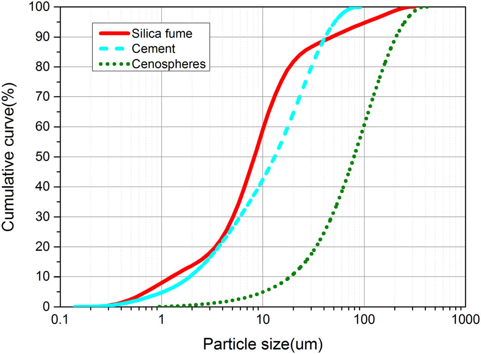
Particle size distribution of powders.
Mechanical and geometrical properties of fibers
| Type | Length (mm) | Diameter (μm) | Elastic modulus (GPa) | Maximum elongation (%) | Tensile strength (MPa) | Density (g/cm3) |
|---|---|---|---|---|---|---|
| PVA | 12 | 39 | 42 | 7 | 1,250 | 1.3 |
| SF | 13 | 220 | 203 | — | 2,850 | 7.8 |
| PE | 12 | 24 | 110 | 2.42 | 3,000 | 0.97 |

Morphology of three fibers: (a) PVA fiber, (b) PE fiber, and (c) SF.
2.2 Mix design and preparation of specimens
The mixtures used in this study are shown in Table 2. The paste matrix mix ratio of the three groups was the same. The cementitious binders included 92.5% cement and 7.5% silica fume by weight. The cenosphere-to-cementitious binder ratio was kept at 0.2. The water-to-cementitious binder ratio was kept at 0.32 and the superplasticizer-to cementitious binder at 0.2%. The PVA-2, PE-2, and SF-2 indicate that the volume blending of PVA fiber, PE fiber, and SF was 2%. The mechanical performance test results of the PVA-2 composite were reported in the author’s previous study [20], and this present study focuses on the effect of fiber type on the mechanical performance and microstructure of lightweight cement-based composites.
Proportions of the mixtures
| Mix ID | Weight ratio of matrix | Fiber (%) | |||||
|---|---|---|---|---|---|---|---|
| Cementitious binders | Cenosphere | Water | PSP | PVA (by volume) | PE (by volume) | SF (by volume) | |
| PVA-2 | 1 | 0.2 | 0.32 | 0.002 | 2 | 0 | 0 |
| PE-2 | 1 | 0.2 | 0.32 | 0.002 | 0 | 2 | 0 |
| SF-2 | 1 | 0.2 | 0.32 | 0.002 | 0 | 0 | 2 |
First, the cement, silica fume, and cenosphere were mixed for 1 min to homogenize the powder mix evenly by using a mortar mixer. Second, water and super-plasticizer were added, and stirring was continued for 2 min. Finally, fibers were slowly added and quickly stirred for 2 min until they were evenly dispersed in slurry to form the cement-based composite. The molds were filled with the fresh cement-based composite, and they were shaken for 30 s using the shaker. The specimens were removed from the mold 1 day later and moved to the curing room for 28 days. The temperature and the relative humidity of the curing room were 20°C and 95%, respectively.
2.3 Test methods
The mechanical property tests of lightweight cement-based composites included compressive and flexural tests, matrix fracture toughness test, uniaxial tensile tests, and single-crack tensile tests. The microscopic morphology tests of lightweight cement-based composites, including scanning electron microscopy (SEM) and fluorescence microscopy, were carried out in this study.
2.3.1 Compressive and flexural tests
Compressive and flexural tests were performed according to the Chinese specification GB/T 17671-1999 [21] to characterize the basic mechanical properties of cement-based composites. The size of specimens for compression cube and flexural prismatic testing were 70.7 × 70.7 × 70.7 mm3 and 40 × 40 × 160 mm3, respectively. The compressive and flexural strengths were obtained as an average of three specimens at 28 days. The compressive test was performed using the hydraulic universal testing machine (WAW-3000) with the loading rate of 0.8 MPa/s. The flexural test was performed using the 250 kN Instron testing machine with the displacement-controlled loading rate of 0.20 mm/min. The flexural test device is shown in Figure 3. The flexural deflection at the mid-span of specimens was measured by two linear variable differential transformers.
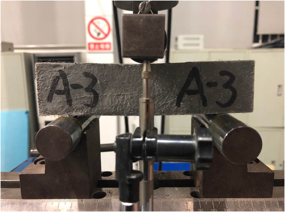
Three-point bending testing set-up.
2.3.2 Uniaxial tensile test
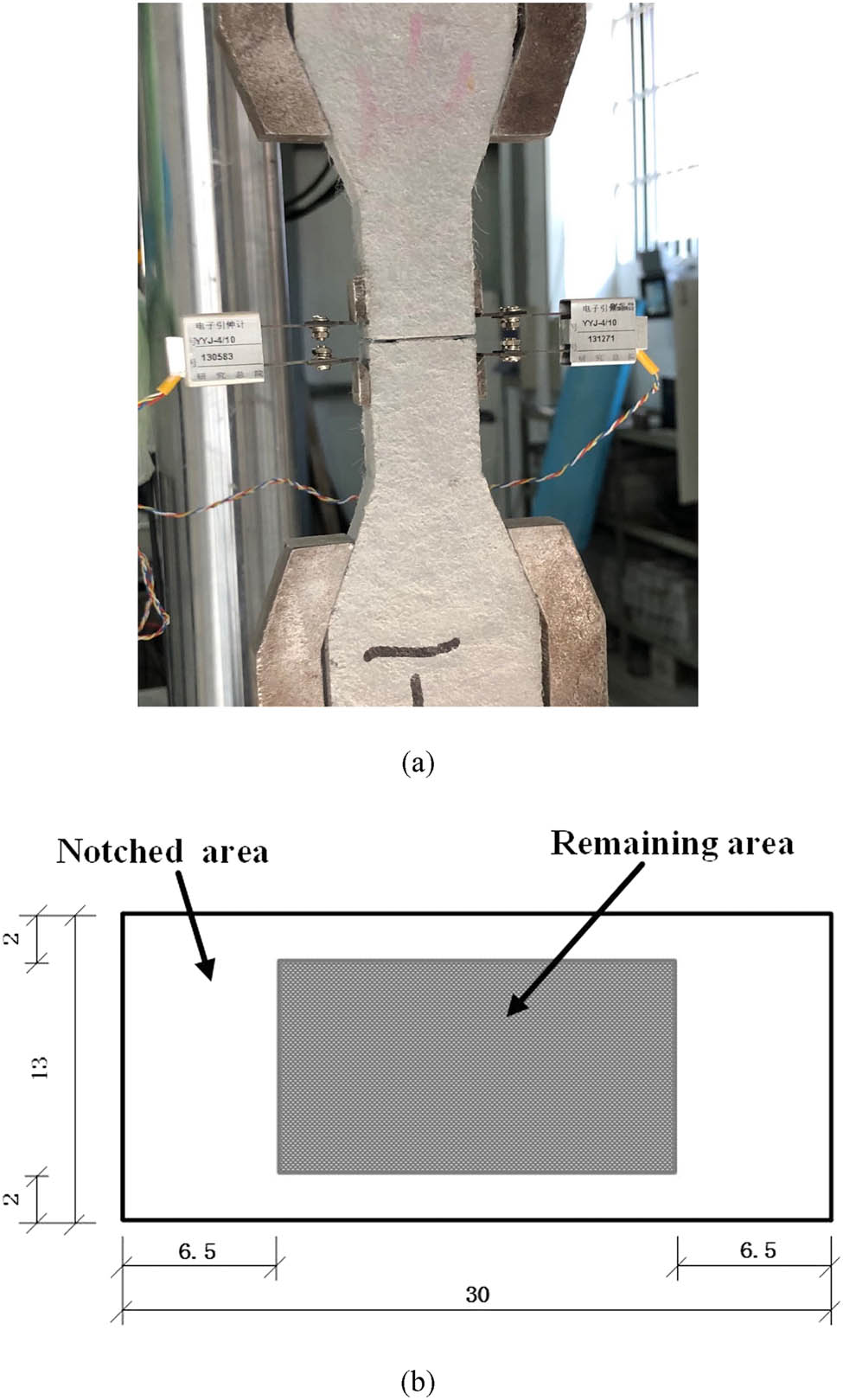
The uniaxial direct tensile test according to the Japan Society of Civil Engineers [22] was performed, as shown in Figure 4. The two linear variable differential transformers were used to record the tensile deformation of the specimen, and its measuring range was 80 mm. The size of the effective cross-sectional dog-bone specimens was 13 × 30 mm2. The uniaxial tensile test was conducted using the same 250 kN Instron testing machine at a displacement speed of 0.2 mm/min to obtain the tensile stress–strain curves of specimens, which could show the strain-hardening ability of the composites.

Uniaxial tensile testing set-up and specimen with LVDT.
2.3.3 Matrix fracture toughness test
To study the micromechanical design principles of the cement-based composites, the fracture toughness of the matrix was obtained by performing three-point bending tests on notched beams, as shown in Figure 5. The maximum load was determined by using the electronic universal testing machine WDW-50 with a speed of 0.2 mm/min according to ASTM E399-12 [23]. The matrix toughness K m can be calculated using equations (1) and (2) [24,25] as follows:
where F Q is the maximum load during the three-point bending test of notched beam test, m is the mass of specimen, g is the gravitational acceleration, S is the span of the beam, a 0 is the depth of the internal notch of the beam, t is the width of the beam, h is the thickness of the beam, and f(α) is the shape parameter of the notched beam.

Matrix toughness testing: (a) device of the test and (b) dimension diagram of the specimen.
2.3.4 Single-crack tensile test
To obtain the important parameters for micromechanical design of the cement-based composites, including the maximum bridging stress and the corresponding crack opening displacement, the single-crack tensile test of the specimen was conducted. The slit with a width of less than 0.6 mm on all four sides of dog-bone specimen was generated using a saw before the single-crack tensile test. Figure 6 shows the single-crack tension test device and the dimensions of single-crack tension specimen. To obtain the tensile stress and crack opening curves of the specimens, the 250 kN Instron testing machine was used for the single-crack tensile tests at a displacement-controlled speed of 0.2 mm/min. The crack opening of the dog-bone specimen was recorded using two electronic extensometers with a measuring range of 10 mm.
Single-crack tensile testing: (a) device of the test and (b) dimension diagram of the specimen.
2.3.5 Fluorescence microscopy and SEM
To evaluate the dispersion of fibers in the composites, the inverted fluorescence microscope Olympus IX53 was used. A small rectangular block was cut from dog-bone specimens, the size of which was 13 × 13 × 30 mm3. The specimen was coated with a fluorescence agent and wards after polishing. After hardening for 15 min, the residual fluorescent agent was washed away using a toothbrush. The fluorescence image was captured using a CCD digital camera through a 40× magnification transmission polarizing microscope filter.
To observe the morphology and the mechanisms of fibers after the specimen was destroyed, the field emission SEM (Quanta FEI) was used. The fracture surface of the dog-bone specimens was obtained. The microscopic morphology of specimens was observed using field emission SEM at a voltage of 10 kV after the crushed specimen was sputtered with gold under vacuum.
3 Results and discussion
3.1 Compressive and flexural strengths
The density and specific strength of the mixtures with different types of fibers are shown in Figure 7. The SFs had a negative influence on the density of the composites due to their greater density, and the density of SF-2 composite reached 1774.79 kg/m3. However, the SF-2 composite had the highest specific strength as shown in Figure 8, and the strength was 88.9 MPa. The compressive strength of the PVA-2 and PE-2 composite at 28 days was 63.2 and 75.5 MPa, respectively, which were decreased by 28.92 and 15.07% compared to those of the SF-2 composite. The improvement of the compressive strength of the composites could be explained by the fact that the incorporation of fibers reduced the lateral tensile strain and improved the energy absorption capacity under the action of compressive load. In addition, the fibers could restrict the expansion of the specimen compression toward the lateral sides [26].
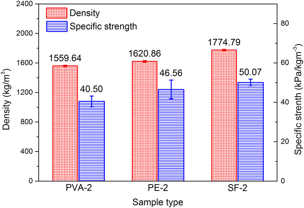
The density and specific strength of lightweight cement-based composites.
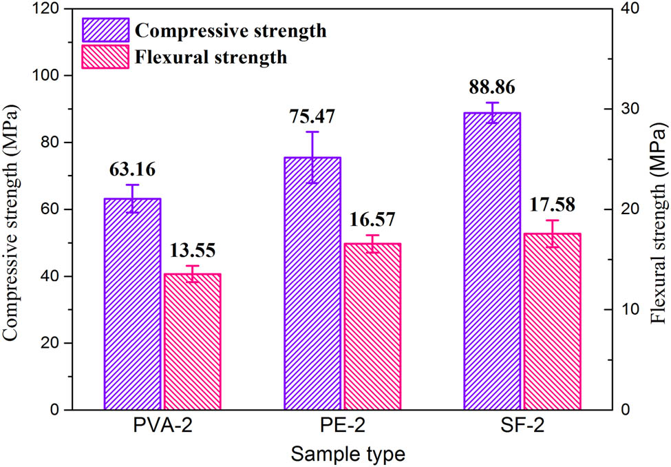
Compressive and flexural strengths of lightweight cement-based composites.
Besides, Figure 8 shows that the flexural strength of the SF-2 composite was higher than that of the PE-2 composite, which was higher than that of the PVA-2 composite for the fiber volume dosage. All the results illustrated that the SF had the most significant enhancement effect on the flexural strength of cement-based composites due to the highest modulus. The high tensile strength of the PE fiber could increase the resistance of cement-based composites against initiation and propagation of the crack. The high bridging stress of the fibers ensured that the cement-based composites had high flexural strength. Previous studies [27,28,29] reported that the matrix and the fiber start to debond at the interface due to the tensile stress being perpendicular to the predicted crack development direction [27,28,29]. Cracks initiate, progress, and cross the fibers during flexural loading. As the crack propagates, the stress concentration at the crack tip decreases due to the action of the faces and the crack width also decreases.
3.2 Bending toughness
The flexural stress–deflection curves of lightweight toughness cement-based composites were determined by three-point bending tests, as shown in Figure 9. Obviously, all specimens exhibit remarkable hardening in bending. The maximum deflection corresponding to the ultimate strength of the PE-2 composite reached 3.02 mm, which was 2.74 times and 5.49 times that of the PVA-2 composite and the SF-2 composite, respectively. Compared with the PVA fibers, the PE fibers had a relatively large effect on the bending toughness of cement-based composites, and the bending toughness of the SF-2 composite was the smallest.
![Figure 9
The flexural stress–deflection behavior of lightweight cement-based composites: (a) PVA-2 [20], (b) PE-2, and (c) SF-2.](/document/doi/10.1515/secm-2021-0021/asset/graphic/j_secm-2021-0021_fig_009.jpg)
The flexural stress–deflection behavior of lightweight cement-based composites: (a) PVA-2 [20], (b) PE-2, and (c) SF-2.
The crack propagation and the width of crack were controlled and limited by the randomly oriented fibers in the cement-based composites. The flexural failure pictures of lightweight toughness cement-based composites are shown in Figure 10. The PE-2 composite exhibited saturated multi-cracks, the PVA-2 composite had multiple cracks near the main crack, and the SF-2 composite had only one failure crack with a larger crack width. This phenomenon could be explained by the fact that the PVA fibers were easily broken under the action of tensile stress due to the relatively low fiber modulus and the high adhesion between the PVA fiber and the matrix. Therefore, the width of the crack in the PVA-2 composite was small. However, the PE and SF composites were prone to slip damage due to the smooth surface and the high modulus. The load remains during the sliding process about constant, and the crack width would continue to increase as the fibers were pulled out. The mechanism of fiber action is described in the following section.

The flexural failure morphology of lightweight cement-based composites: (a) PVA-2, (b) PE-2, and (c) SF-2.
3.3 Tensile ductility
The uniaxial tensile stress–strain curves of specimens with different fibers are shown in Figure 11. The peak stress corresponding to the first falling section in the curve was the initial crack strength. Although the matrix of the three mixtures was the same, the initial crack strength of the SF-2 composite was higher than that of the PVA-2 and the PE-2 composite. This illustrates that a difference in fiber diameter, elastic modulus, strength, and elongation causes different initial crack strength of the mixtures. Besides, the porosity of the matrix near the fiber was smaller because the PVA fiber was more hydrophilic than the PE fiber, and therefore the initial crack strength obtained by the test was higher.
![Figure 11
The uniaxial tensile stress–strain curves of lightweight cement-based composites: (a) PVA-2 [20], (b) PE-2, and (c) SF-2.](/document/doi/10.1515/secm-2021-0021/asset/graphic/j_secm-2021-0021_fig_011.jpg)
The uniaxial tensile stress–strain curves of lightweight cement-based composites: (a) PVA-2 [20], (b) PE-2, and (c) SF-2.
The tensile strength and the ultimate tensile strain of the PVA-2 composite reached 4.14 MPa and 1.56%, respectively, which was 1.17 times and 39 times than that of the SF-2 composite. The tensile strength and the ultimate tensile strain of the PE-2 composite were the highest, which were 3.29 MPa and 2.56%, respectively. The PE-2 composite exhibited distinguished strain-hardening behavior and multiple cracking was observed, which illustrates that the PE fibers had good bridging effects. When the matrix was cracked, the PE fiber at the crack completely bore the stress generated by the matrix cracking. The stress is transmitted to the surrounding matrix without cracking through the bonding between the fiber and the matrix [30,31]. As the load increased, the stress transmitted by the fibers continued to increase until the surrounding matrix reached the cracking load, and a new crack appeared, and the specimen showed multiple cracks after repeating this process. The sum of bonding forces between the PE fibers and the matrix was lower than the cracking stress of the matrix; the main cracks began to expand and the bearing capacity of the specimen gradually decreased, and the specimen reached the failure state.
To investigate the mechanism of high ductility based on the micromechanical design theory, the fracture toughness of the specimen was obtained by the three-point bending test of the notched beam. The calculated fracture toughness of the matrix is listed in Table 3. To achieve the pseudo-strain hardening behavior of a cement-based composite, two important criteria need to be fulfilled. The first one is that the maximum fiber bridging stress should be more than the first-crack strength of the matrix. The second one is that the complementary energy must be more than the fracture energy of matrix. The fracture energy of matrix J tip and the complementary energy J b′ can be calculated using equations (3) and (4) [32,33] as follows:
where σ fc and δ 0 are the maximum fiber bridging stress and the corresponding crack opening displacement, respectively. K m is the fracture toughness of matrix and E m is the Young’s modulus of the matrix. The schematic diagram of equation (3) is shown in Figure 12.
Fracture toughness of the matrix
| Sample | Mass/(g) | Peak load/(N) | Matrix fracture toughness K m/(kPa m1/2) | Fracture energy J tip/(J/m2) |
|---|---|---|---|---|
| 1 | 433.8 | 519.5 | 257.63 | 6.27 |
| 2 | 432.2 | 513.5 | 254.73 | 6.13 |
| 3 | 432.0 | 503.5 | 249.97 | 5.91 |
| Average | 432.7 | 512.2 | 254.11 | 6.10 |
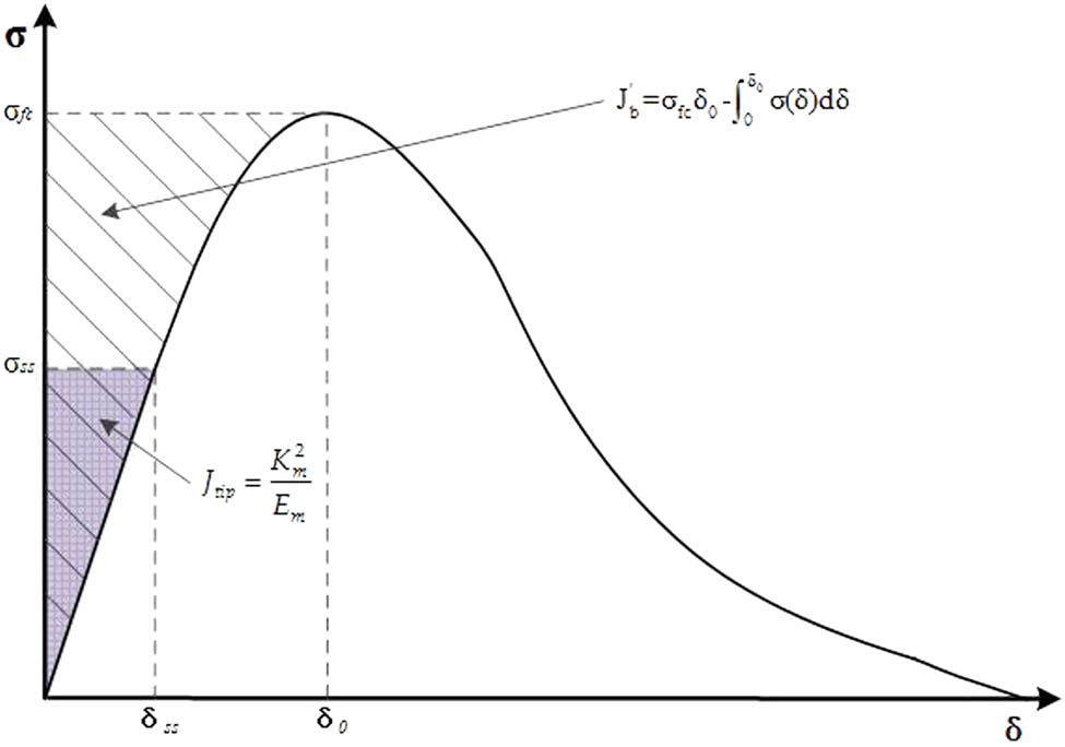
Typical σ–δ curve of the cement-based composites.
The single-crack tensile tests of the dog-bone specimen were performed to obtain the fiber bridging complementary energy and the maximum bridging stress. The test curves are shown in Figure 13. The calculated complementary energy, the corresponding crack opening displacement, and the maximum bridging stress are listed in Table 4. The maximum bridging stress of the PE fiber composite reached 6.71 MPa, which was much higher than that of the PVA and the SFs. Besides, the calculated complementary energy and the corresponding crack opening displacement of the PE fiber were 1152.40 J/m2 and 0.84 mm, respectively, which were also much greater than that of the PVA and the SF composites.
![Figure 13
The single-crack tensile curves of lightweight cement-based composites: (a) PVA-2 [20], (b) PE-2, and (c) SF-2.](/document/doi/10.1515/secm-2021-0021/asset/graphic/j_secm-2021-0021_fig_013.jpg)
The single-crack tensile curves of lightweight cement-based composites: (a) PVA-2 [20], (b) PE-2, and (c) SF-2.
Results of notched uniaxial tensile test
| Sample | Maximum bridging stress σ fc (MPa) | Maximum crack opening displacement δ 0 (mm) | Complementary energy J b′ (J/m2) | First-crack strength of the matrix σ 0 (MPa) |
|---|---|---|---|---|
| PVA-2 | 5.19 (0.099) | 0.20 (0.166) | 194.70 (0.181) | 2.82 (0.061) |
| PE-2 | 6.71 (0.154) | 0.84 (0.629) | 1152.40 (0.153) | 2.30 (0.097) |
| SF-2 | 4.16 (0.043) | 0.21 (0.493) | 191.37 (0.562) | 2.87 (0.054) |
Note: The numbers in parentheses are the coefficients of variation of the corresponding parameter.
The two indicators to quantify the robustness of tensile ductility of the composites were proposed by Marshall and Cox [34], which include the strength index pseudo-strain hardening PSHS (= σ fc/σ 0) and the energy index pseudo-strain hardening PSHE (= J b′/J tip). The calculated pseudo-strain hardening indexes of lightweight cement-based composites are shown in Figure 14. Kanda and Li [35] reported that PSHE > 3 and PSHS > 1.2 were the basic condition for ensuring saturated multi-crack cracking. The calculated results of lightweight cement-based composites with different fiber types in this study met the above requirements. The strength index of the PE-2 composite was 58.70 and 100.01% higher than those of the PVA-2 composite and the SF-2 composite, respectively. The energy index of the PE-2 composite was 5.92 times and 6.02 times than that of the PVA-2 composite and the SF-2 composite, respectively. The result illustrates that the PE fiber had the largest effect on the tensile ductility of lightweight cement-based composites due to its very high bridging capability.
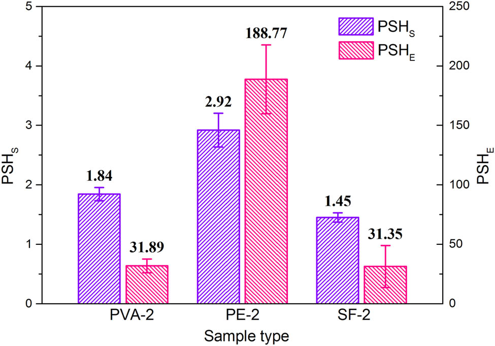
Two pseudo-strain hardening indexes of lightweight cement-based composites.
3.4 Fiber dispersibility
Due to the hydrophobic character and small diameter of the PE fibers, the dispersion of PE fibers in cement-based composites was difficult to observe. The PVA and the SFs’ dispersion diagram in lightweight cement-based composites are shown in Figure 15. The dispersion of the PVA and the SF fibers was good due to the moderate viscosity of the matrix in this study. It was reported in the literature [36] that the cement mortar with a viscosity within the optimal range had a higher shear force, which was beneficial to the dispersion of fibers. A good dispersion of fibers helps improve the tensile ductility of lightweight cement-based composites.

Fiber dispersion in lightweight cement-based composites. (a) PVA; (b) SF.
3.5 Microstructure
Figure 16 shows the fracture shape of the specimens after the tensile test. It can be seen that most of the PVA fibers ruptured, while most of the PE and the SFs were pulled out. This was the result of the high strength and modulus of the PE fibers, and they were pulled out during the multi-cracking process. Therefore, stable multiple cracking and strain-hardening behavior were easier to achieve. Due to the smooth surface of the SF and the low adhesion between the SFs and the matrix, the stress level with the surrounding substrate through the bonding was limited. Therefore, multiple cracking behavior of lightweight cement-based composites incorporated with SFs was not obtained.
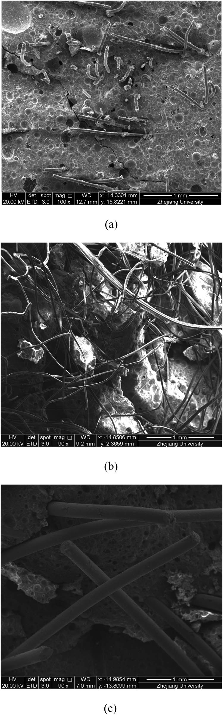
SEM image of the fracture specimen with different fiber types. (a) PVA; (b) PE; (c) SF.
To further explore the mechanism of fiber to increase the ductility, the fracture morphology of the fiber and the adhesion of the fiber with the cement paste were analyzed. The elemental analysis was carried out at the fiber surface by using energy spectrometer. Figure 17a shows that the PVA fibers ruptured due to the jagged fracture, and many particles adhered to the surface of the PVA fibers. The energy spectrum test was carried out on points 1 and 2 as indicated in Figure 17a, and the results are shown in Figure 18 and Table 5. The particles adhering to the surface of the PVA fiber were hydration products with high calcium content. Figure 17b shows that PVA fiber adhered well to the cement paste, and the interface transition zone is covered with some hydration products. The cement paste adhered to the PVA fiber under the action of stretching, and the cement paste showed micro-cracks, which also confirms the strong adhesion between the PVA fibers and the cement paste.
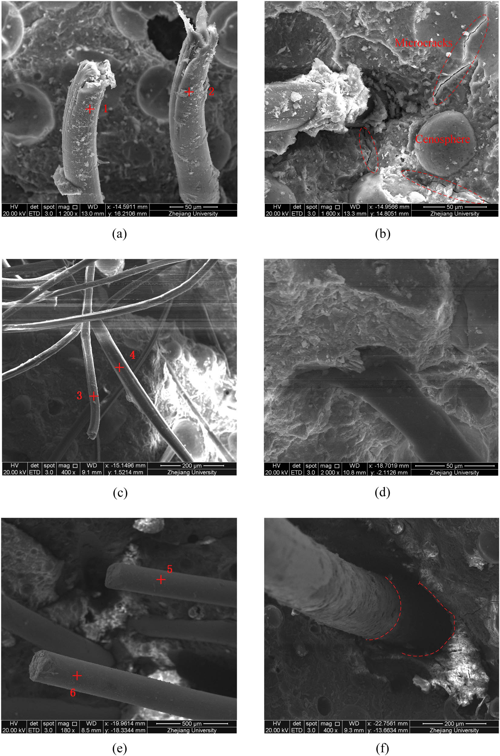
Different types of fiber morphology in lightweight cement-based composites after the uniaxial tensile test. (a) PVA; (b) PVA; (c) PE; (d) PE; (e) SF; (f) SF.
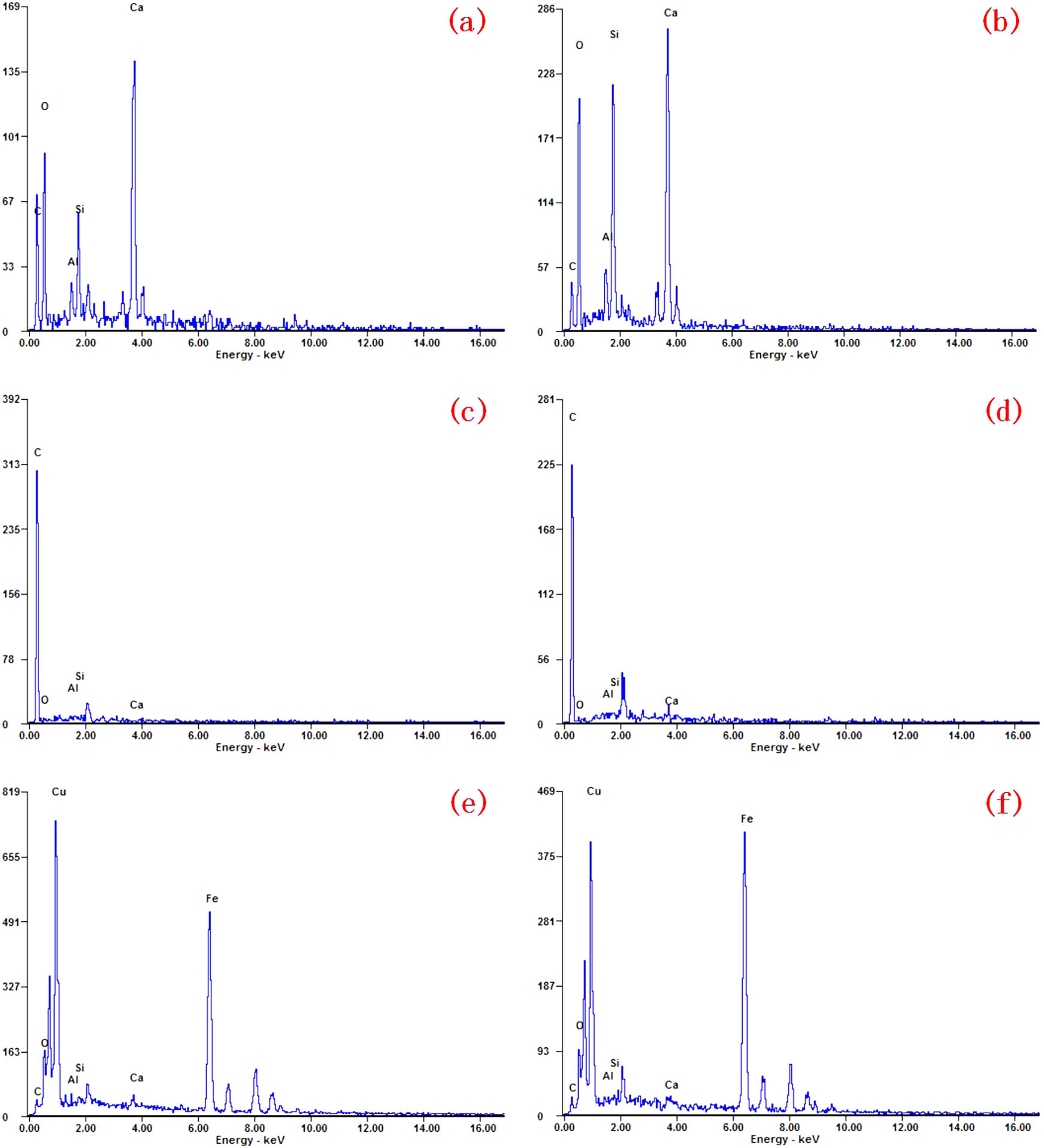
EDS spectrum of the fiber surface: (a) point 1, (b) point 2, (c) point 3, (d) point 4, (e) point 5, and (f) point 6.
Element mass percentage of fiber surface
| Element | Point 1 | Point 2 | Point 3 | Point 4 | Point 5 | Point 6 |
|---|---|---|---|---|---|---|
| Ca | 29.11 | 26.70 | 0.51 | 4.16 | 0.94 | 0.66 |
| Si | 6.58 | 3.45 | 0.78 | 1.59 | 0.67 | 0.26 |
| Al | 2.97 | 3.45 | 0.89 | 0.96 | 0.53 | 0.11 |
| O | 40.99 | 46.61 | 7.22 | 1.25 | 3.75 | 3.94 |
| C | 20.35 | 10.21 | 90.60 | 92.03 | 1.26 | 2.21 |
| Cu | — | — | — | — | 56.13 | 50.06 |
| Fe | — | — | — | — | 36.72 | 42.76 |
Figure 17c and d shows that the PE fiber was pulled out due to the flat fracture, and the surface of the PE fiber was smooth and clean. Besides, there was a certain gap between the PE fiber and the cement paste. According to Figure 18 and Table 5, the energy spectrum test of the PE fiber surface showed that carbon quality accounts for more than 90% in the surface element, which confirmed that no hydration product adhered to the PE fiber surface. The chemical bonding ability between the PE fibers and the cement paste was relatively weak due to the hydrophobic PE fiber, which causes the fiber and the cement paste debonding. This phenomenon helped the fiber play a bridging role after the initial cracking of the cement paste. Therefore, the strain-hardening characteristics exhibited during the tensile process show that the multiple cracks occurred macroscopically.
It is observed from Figure 17e and f that the SFs were pulled out due to the flat fracture similar to the PE fiber. However, there was the large gap between the SF and the cement paste. The layer of copper coating on the surface of the SF prevents rust. Therefore, the elements of the SF surface are mainly copper and iron, which illustrates that no hydration product adhered to the SF surface. The bridging effect of the SFs was not strong due to the much lower adhesion between the SFs and cement paste, which caused it difficult to achieve multiple cracks behavior.
4 Conclusion
The mechanical properties of lightweight cement-based composites containing PVA, PE, or SFs have been studied in this article. Besides, this article explored the toughening mechanism of different types of fibers. The results show that SFs have the most significant effect in improving the strength of lightweight cement-based composites. The specific strength and compressive strength of lightweight cement-based composites containing SFs were 50.07 kPa/kg m−3 and 88.86 MPa, respectively. Meanwhile, its flexural strength reached 17.58 MPa. However, comparing the contribution of PVA and SFs, the PE fiber improvement reached more toughness and ductility. The maximum flexural deflection and the ultimate tensile strain were 3.02 mm and 2.56%, respectively. Lightweight cement-based composites containing PE fibers exhibit remarkable strain-hardening behavior and multiple cracking in the uniaxial tensile test due to very high bridging capability provided by the PE fibers. Besides, the dispersion effect of the PVA and the SFs was good due to the moderate viscosity of the cement matrix in this study. A larger amount of hydration products adhered to the surface of the PVA fiber, which improved the adhesion between the cement matrix and the PVA fibers and caused most of the PVA fibers to rupture. However, the chemical bonding ability between the PE fibers and the cement paste was relatively weak due to the hydrophobic character, which causes fibers and the cement paste debonding and helps the fibers play a bridging role during pull-out after the initial cracking of the cement paste. In general, the superior tensile ductility of lightweight cement-based composites can meet the needs of construction and transportation engineering for material deformability. The findings of this study provide a good reference for future research and the application of new lightweight cement-based composites in real constructions.
Acknowledgments
This study was supported by Zhejiang Provincial Transportation Science and Technology Project of China (2018C03029) and Zhejiang Provincial Construction Research Project of China (2018K021).
-
Conflict of interest: Authors state no conflict of interest.
References
[1] Bentur A, Igarashi S, Kovler K. Prevention of autogenous shrinkage in high-strength concrete by internal curing using wet lightweight aggregates. Cem Concr Res. 2001;31:1587–91.10.1016/S0008-8846(01)00608-1Search in Google Scholar
[2] Sengul O, Azizi S, Karaosmanoglu F, Tasdemir MA. Effect of expanded perlite on the mechanical properties and thermal conductivity of lightweight concrete. Energy Build. 2011;43:671–6.10.1016/j.enbuild.2010.11.008Search in Google Scholar
[3] Demirboga R, Gul R. The effects of expanded perlite aggregate, silica fume and fly ash on the thermal conductivity of lightweight concrete. Cem Concr Res. 2003;33:723–7.10.1016/S0008-8846(02)01032-3Search in Google Scholar
[4] Hossain KMA. Properties of volcanic pumice based cement and lightweight concrete. Cem Concr Res. 2004;34:283–91.10.1016/j.cemconres.2003.08.004Search in Google Scholar
[5] Nikbin IM, Aliaghazadeh M, Charkhtab S, Fathollahpour A. Environmental impacts and mechanical properties of lightweight concrete containing bauxite residue (red mud). J Clean Prod. 2018;172:2683–94.10.1016/j.jclepro.2017.11.143Search in Google Scholar
[6] Sadrmomtazi A, Sobhani J, Mirgozar MA. Modeling compressive strength of EPS lightweight concrete using regression, neural network and ANFIS. Constr Build Mater. 2013;42:205–16.10.1016/j.conbuildmat.2013.01.016Search in Google Scholar
[7] Babu KG, Babu DS. Performance of fly ash concretes containing lightweight EPS aggregates. Cem Concr Compos. 2004;26:605–11.10.1016/S0958-9465(03)00034-9Search in Google Scholar
[8] Kashani A, Ngo TD, Mendis P, Black JR, Hajimohammadi A. A sustainable application of recycled tyre crumbs as insulator in lightweight cellular concrete. J Clean Prod. 2017;149:925–35.10.1016/j.jclepro.2017.02.154Search in Google Scholar
[9] Li Z, Wang L, Wang X. Flexural characteristics of coir fiber reinforced cementitious composites. Fiber Polym. 2006;7:286–94.10.1007/BF02875686Search in Google Scholar
[10] Ismail MR, Yassen AAM, Afify MS. Mechanical properties of rice straw fiber-reinforced polymer composites. Fiber Polym. 2011;12:648–56.10.1007/s12221-011-0648-5Search in Google Scholar
[11] Abdi A, Eslami-Farsani R, Khosravi H. Evaluating the mechanical behavior of basalt fibers/epoxy composites containing surface-modified CaCO3 nanoparticles. Fiber Polym. 2018;19:635–40.10.1007/s12221-018-7755-xSearch in Google Scholar
[12] Pakravan HR, Latifi M, Jamshidi M. Hybrid short fiber reinforcement system in concrete: a review. Constr Build Mater. 2017;142:280–94.10.1016/j.conbuildmat.2017.03.059Search in Google Scholar
[13] Wu Z, Shi C, He W, Wu L. Effects of steel fiber content and shape on mechanical properties of ultra high performance concrete. Constr Build Mater. 2016;103:8–14.10.1016/j.conbuildmat.2015.11.028Search in Google Scholar
[14] Akca KR, Cakir O, Ipek M. Properties of polypropylene fiber reinforced concrete using recycled aggregates. Constr Build Mater. 2015;98:620–30.10.1016/j.conbuildmat.2015.08.133Search in Google Scholar
[15] Meesala CR. Influence of different types of fiber on the properties of recycled aggregate concrete. Struct Concr. 2019;20:1656–69.10.1002/suco.201900052Search in Google Scholar
[16] Bangi MR, Horiguchi T. Effect of fiber type and geometry on maximum pore pressures in fibre-reinforced high strength concrete at elevated temperatures. Cem Concr Res. 2012;42:459–66.10.1016/j.cemconres.2011.11.014Search in Google Scholar
[17] Branston J, Das S, Kenno SY, Taylor C. Mechanical behaviour of basalt fibre reinforced concrete. Constr Build Mater. 2016;124:878–86.10.1016/j.conbuildmat.2016.08.009Search in Google Scholar
[18] Mastali M, Dalvand A, Sattarifard AR. The impact resistance and mechanical properties of reinforced self-compacting concrete with recycled glass fibre reinforced polymers. J Clean Prod. 2016;124:312–24.10.1016/j.jclepro.2016.02.148Search in Google Scholar
[19] Liu J, Jia Y, Wang J. Experimental study on mechanical and durability properties of glass and polypropylene fiber reinforced concrete. Fiber Polym. 2019;20:1900–8.10.1007/s12221-019-1028-9Search in Google Scholar
[20] Chen W, Qi Z, Zhang L, Huang Z. Effects of cenosphere on the mechanical properties of cement-based composites. Constr Build Mater. 2020;261:120527.10.1016/j.conbuildmat.2020.120527Search in Google Scholar
[21] IOS/TC 74. Method of testing cements determination of strength GB/T 17671–1999. Beijing, China; 1999.Search in Google Scholar
[22] Japan Society of Civil Engineers (JSCE). Recommendations for design and construction of high performance fiber reinforced cement composites with multiple fine cracks. Tokyo, Japan; 2008.Search in Google Scholar
[23] ASTM E399-12. Standard test method for linear-elastic plane-strain fracture toughness of KIC metallic material. ASTM International 1–33; 2012.Search in Google Scholar
[24] Xu S, Reinhardt HW. Determination of double-K criterion for crack propagation in quasi-brittle fracture, part II: analytical evaluating and practical measuring methods for three-point bending notched beams. Int J Fract. 1999;98:151–77.10.1023/A:1018740728458Search in Google Scholar
[25] Yu K, Wang Y, Yu J, Xu S. A strain-hardening cementitious composites with the tensile capacity up to 8%. Constr Build Mater. 2017;137:410–9.10.1016/j.conbuildmat.2017.01.060Search in Google Scholar
[26] Wang X, Zhang S, Wang C, Cao K, Wei P, Wang J. Effect of steel fibers on the compressive and splitting-tensile behaviors of cellular concrete with millimeter-size pores. Constr Build Mater. 2019;221:60–73.10.1016/j.conbuildmat.2019.06.069Search in Google Scholar
[27] Li Y, Reese S, Simon JW. Modeling the fiber bridging effect in cracked wood and paperboard using a cohesive zone model. Eng Fract Mech. 2018;196:83–97.10.1016/j.engfracmech.2018.04.002Search in Google Scholar
[28] Kanda T, Li VC. Effect of fiber strength and fiber-matrix interface on crack bridging in cement composites. J Eng Mech. 1999;125:290–9.10.1061/(ASCE)0733-9399(1999)125:3(290)Search in Google Scholar
[29] Wang Y, Anandakumar U, Singh R. Effect of fiber bridging stress on the fracture resistance of silicon-carbide-fiber/zircon composites. J Am Ceram Soc. 2000;83:1207–14.10.1111/j.1151-2916.2000.tb01355.xSearch in Google Scholar
[30] Mu B, Meyer C, Shimanovich S. Improving the interface bond between fiber mesh and cementitious matrix. Cem Concr Res. 2002;32:783–7.10.1016/S0008-8846(02)00715-9Search in Google Scholar
[31] Curosu I, Mechtcherine V, Millon O. Effect of fiber properties and matrix composition on the tensile behavior of strain-hardening cement-based composites (SHCCs) subject to impact loading. Cem Concr Res. 2016;82:23–5.10.1016/j.cemconres.2015.12.008Search in Google Scholar
[32] Li VC, Leung CKY. Steady-state and multiple cracking of short random fiber composites. J Eng Mech. 1992;118:2246–64.10.1061/(ASCE)0733-9399(1992)118:11(2246)Search in Google Scholar
[33] Li VC, Wang S, Wu C. Tensile strain-hardening behavior of polyvinyl alcohol engineered cementitious composite (PVA-ECC). ACI Mater J. 2001;98:483–92.10.14359/10851Search in Google Scholar
[34] Marshall DB, Cox BN. A j-integral method for calculating steady-state matrix cracking stresses in composites. Mech Mater. 1988;7:127–33.10.1016/0167-6636(88)90011-7Search in Google Scholar
[35] Kanda T, Li VC. Multiple cracking sequence and saturation in fiber reinforced cementitious composites. Concr Res Technol. 1998;9:19–33.10.3151/crt1990.9.2_19Search in Google Scholar
[36] Lei D, Guo L, Chen B, Curosu I, Mechtcherine V. The connection between microscopic and macroscopic properties of ultra-high strength and ultra-high ductility cementitious composites (UHS-UHDCC). Compos B Eng. 2019;164:144–57.10.1016/j.compositesb.2018.11.062Search in Google Scholar
© 2021 Wenhua Chen et al., published by De Gruyter
This work is licensed under the Creative Commons Attribution 4.0 International License.
Articles in the same Issue
- Effects of Material Constructions on Supersonic Flutter Characteristics for Composite Rectangular Plates Reinforced with Carbon Nano-structures
- Processing of Hollow Glass Microspheres (HGM) filled Epoxy Syntactic Foam Composites with improved Structural Characteristics
- Investigation on the anti-penetration performance of the steel/nylon sandwich plate
- Flexural bearing capacity and failure mechanism of CFRP-aluminum laminate beam with double-channel cross-section
- In-Plane Permeability Measurement of Biaxial Woven Fabrics by 2D-Radial Flow Method
- Regular Articles
- Real time defect detection during composite layup via Tactile Shape Sensing
- Mechanical and durability properties of GFRP bars exposed to aggressive solution environments
- Cushioning energy absorption of paper corrugation tubes with regular polygonal cross-section under axial static compression
- An investigation on the degradation behaviors of Mg wires/PLA composite for bone fixation implants: influence of wire content and load mode
- Compressive bearing capacity and failure mechanism of CFRP–aluminum laminate column with single-channel cross section
- Self-Fibers Compacting Concrete Properties Reinforced with Propylene Fibers
- Study on the fabrication of in-situ TiB2/Al composite by electroslag melting
- Characterization and Comparison Research on Composite of Alluvial Clayey Soil Modified with Fine Aggregates of Construction Waste and Fly Ash
- Axial and lateral stiffness of spherical self-balancing fiber reinforced rubber pipes under internal pressure
- Influence of technical parameters on the structure of annular axis braided preforms
- Nano titanium oxide for modifying water physical property and acid-resistance of alluvial soil in Yangtze River estuary
- Modified Halpin–Tsai equation for predicting interfacial effect in water diffusion process
- Experimental research on effect of opening configuration and reinforcement method on buckling and strength analyses of spar web made of composite material
- Photoluminescence characteristics and energy transfer phenomena in Ce3+-doped YVO4 single crystal
- Influence of fiber type on mechanical properties of lightweight cement-based composites
- Mechanical and fracture properties of steel fiber-reinforced geopolymer concrete
- Handcrafted digital light processing apparatus for additively manufacturing oral-prosthesis targeted nano-ceramic resin composites
- 3D printing path planning algorithm for thin walled and complex devices
- Material-removing machining wastes as a filler of a polymer concrete (industrial chips as a filler of a polymer concrete)
- The electrochemical performance and modification mechanism of the corrosion inhibitor on concrete
- Evaluation of the applicability of different viscoelasticity constitutive models in bamboo scrimber short-term tensile creep property research
- Experimental and microstructure analysis of the penetration resistance of composite structures
- Ultrasensitive analysis of SW-BNNT with an extra attached mass
- Active vibration suppression of wind turbine blades integrated with piezoelectric sensors
- Delamination properties and in situ damage monitoring of z-pinned carbon fiber/epoxy composites
- Analysis of the influence of asymmetric geological conditions on stability of high arch dam
- Measurement and simulation validation of numerical model parameters of fresh concrete
- Tuning the through-thickness orientation of 1D nanocarbons to enhance the electrical conductivity and ILSS of hierarchical CFRP composites
- Performance improvements of a short glass fiber-reinforced PA66 composite
- Investigation on the acoustic properties of structural gradient 316L stainless steel hollow spheres composites
- Experimental studies on the dynamic viscoelastic properties of basalt fiber-reinforced asphalt mixtures
- Hot deformation behavior of nano-Al2O3-dispersion-strengthened Cu20W composite
- Synthesize and characterization of conductive nano silver/graphene oxide composites
- Analysis and optimization of mechanical properties of recycled concrete based on aggregate characteristics
- Synthesis and characterization of polyurethane–polysiloxane block copolymers modified by α,ω-hydroxyalkyl polysiloxanes with methacrylate side chain
- Buckling analysis of thin-walled metal liner of cylindrical composite overwrapped pressure vessels with depressions after autofrettage processing
- Use of polypropylene fibres to increase the resistance of reinforcement to chloride corrosion in concretes
- Oblique penetration mechanism of hybrid composite laminates
- Comparative study between dry and wet properties of thermoplastic PA6/PP novel matrix-based carbon fibre composites
- Experimental study on the low-velocity impact failure mechanism of foam core sandwich panels with shape memory alloy hybrid face-sheets
- Preparation, optical properties, and thermal stability of polyvinyl butyral composite films containing core (lanthanum hexaboride)–shell (titanium dioxide)-structured nanoparticles
- Research on the size effect of roughness on rock uniaxial compressive strength and characteristic strength
- Research on the mechanical model of cord-reinforced air spring with winding formation
- Experimental study on the influence of mixing time on concrete performance under different mixing modes
- A continuum damage model for fatigue life prediction of 2.5D woven composites
- Investigation of the influence of recyclate content on Poisson number of composites
- A hard-core soft-shell model for vibration condition of fresh concrete based on low water-cement ratio concrete
- Retraction
- Thermal and mechanical characteristics of cement nanocomposites
- Influence of class F fly ash and silica nano-micro powder on water permeability and thermal properties of high performance cementitious composites
- Effects of fly ash and cement content on rheological, mechanical, and transport properties of high-performance self-compacting concrete
- Erratum
- Inverse analysis of concrete meso-constitutive model parameters considering aggregate size effect
- Special Issue: MDA 2020
- Comparison of the shear behavior in graphite-epoxy composites evaluated by means of biaxial test and off-axis tension test
- Photosynthetic textile biocomposites: Using laboratory testing and digital fabrication to develop flexible living building materials
- Study of gypsum composites with fine solid aggregates at elevated temperatures
- Optimization for drilling process of metal-composite aeronautical structures
- Engineering of composite materials made of epoxy resins modified with recycled fine aggregate
- Evaluation of carbon fiber reinforced polymer – CFRP – machining by applying industrial robots
- Experimental and analytical study of bio-based epoxy composite materials for strengthening reinforced concrete structures
- Environmental effects on mode II fracture toughness of unidirectional E-glass/vinyl ester laminated composites
- Special Issue: NCM4EA
- Effect and mechanism of different excitation modes on the activities of the recycled brick micropowder