Optimization for drilling process of metal-composite aeronautical structures
-
Cristiano Devitte
 ,
Gabriel S. C. Souza
,
Gabriel S. C. Souza

Abstract
Metal-composite laminates and joints are applied in aircraft manufacturing and maintenance (repairing) using aluminum alloys (AA) and glass fiber-reinforced polymer (GFRP). In these applications, drilling has a prominent place due to its vast application in aeronautical structures’ mechanical joints. Thus, this study presents the influence of uncoated carbide drills (85C, 86C, H10N), cutting speeds (v
c = 20, 40, and 60 m min−1), and feed rates (f = 0.05, 0.15, and 0.25 mm rev−1) on delamination factor, thrust force (
1 Introduction
The advent of new processing techniques and cutting tools ensures that composite and hybrid materials have been used in several engineering fields, especially in aeronautical, aerospace, and automobile industries [1,2]. Fiber-reinforced polymer matrix composites (FRPs) are widely used in the aerospace industry [1,2,3,4,5,6], with carbon (CFRP) and glass (GFRP) fibers being the most used reinforcements and, consequently, the most studied [3,6,7,8]. As it is known, in general, the mechanical properties of CFRP are superior to those of GFRP. However, the machinability of both materials is similar [9].
Manufacturers need to drill approximately one million holes in structural components to assemble one aircraft’s fuselage in the aeronautical industry. In general, aeronautical structures consist of sheets made from different materials (such as sandwich panels) that are connected by mechanical joints (using fasteners) of metal/metal, metal/composite, and composite/composite parts [10]. The aerospace industry reaches 40 million holes per year, 80% of which are obtained manually, preceding mechanical fasteners [11]. About 60% of the hybrid structural components that are rejected by the aeronautical industry have defects directly related to the drilling process [6]. Combined with the parts’ high added value, this fact makes drilling composite materials and metal-composite laminate subject to constant investigations [12].
The drilling of hybrid metal/composite stack is the main challenge due to different phenomena, such as delamination [5] and damage in the polymer matrix and fibers due to thermal gradients from metal chips [6]. Furthermore, it is challenging to select optimal cutting parameters and tools to guarantee machining quality and surface integrity for all constituents (fibers and matrix) [4,5].
Zitoune et al. [6,13] verified that the most common problems in drilling metal-composite laminate CFRP/Al were (i) damage due to the interaction between composite surface and continuous chips, which comes from machining Al; (ii) separation of composite ply from the metal ply due to high thrust forces, producing an accumulation of aluminum chips and fiber fragments at the CFRP/Al interface; and (iii) adhesion of a metallic layer along the entire cutting edge.
The CFRP delamination directly affects the quality of the assembly of hybrid structures. The degree of defects represents the drilling quality characterized by the so-called spalling at the hole exit. The feed rate effect is often higher than the spindle speed; then, it is necessary to control the thrust force when the chisel edge is in contact with the exit surface of the plate [14]. The mechanical performance of the metal-composite laminate stack decreases, especially when subjected to cyclic loads (fatigue), and can be mainly identified in the region of entry and exit of the cutting tool [1]. Damage caused by delamination in the tool exit is higher than that caused in the entrance [15,16]. The delamination in the tool entrance (peel-up) can be considered a consequence of the contact between the drill tip and upper layers of laminate. Conversely, in the tool exit (push-out), damage is caused by the compressive loadings applied by the end of the drill on the upper layers of the laminate [17]. The usage of the digital analysis is suitable to estimate damages after drilling. This kind of failure can be quantified using the delamination factor (
Different authors concluded that the feed rate is the most relevant input parameter on delamination factor [16,21,22,23,24,25,26,27,28] and thrust force [20,21,22,24,26,27,28,29] during the drilling GFRP. Others have also verified the influence of the drill. Srinivasan et al. [25] showed that the drill diameter strongly influences the delamination results. Gaitonde et al. [27] showed that a lower point angle combined with the feed rate could reduce the damage. Batista et al. [26] confirmed that the tool geometry affects delamination and thrust force. Rubio et al. [29] also observed that the drill geometry and drill wear influence delamination and thrust force. Davim and Reis [30] identified that carbide is a better choice than HSS for drilling CFRP and null wear in the flank surface, while the HSS drill presents wear of 0.012 mm. Abrão et al. [31] verified the highest thrust force values for drills with three cutting edges. Rubio et al. [32] identified high-speed machining (HSM) contribution for drilling GFRP to ensure low damage levels.
Considering the process of generating through-holes in ductile metals by the drilling process with a twist drill, burrs may occur at the holes’ exit. Furthermore, drills with smaller point angles generate higher forces and plastic deformation in the holes’ central part, generating crown burrs. However, larger point angles can distribute better the forces at the periphery of the holes, causing a complete or partial fracture and generating smooth burrs, which are more easily removed. If a partial fracture takes place, a hat burr occurs [33]. Moreover, Pinto [34] found that drills with smaller helix angles generate the best results when thin sheets of AA2024 are drilled, mainly at the holes’ exit, decreasing the subsequent deburring steps.
The deburring step, which is often required after the manufacturing process, is not usually done in an automated way but manual. Thus, it implies the qualified workforce, specific equipment, and process time increment, causing increased production costs [35,36,37].
Considering the scenario pointed earlier, the present work’s contribution consists of finding the optimal combination for values of different parameters involved in the drilling process, such as the drill type, the cutting speed, and the feed rate to minimize the delamination factor, the thrust force, and burr formation generated during drilling of a hybrid composite laminate, AA2024/GFRP/AA2024 stack, applied in aeronautical structures. Thus, the Box–Behnken design (BBD) was performed for experimental analysis and input parameters optimization. Finally, based on the results, some relevant conclusions and recommendations are highlighted for the drilling of hybrid composite laminate joined by fasteners and used in aeronautical structures.
2 Materials and methods
2.1 Hybrid composite stack
The metal-composite laminate used in the tests was obtained by stacking two AA2024 (Al) plates with 1.0 mm thickness and one plate of glass fiber-reinforced polymer (GFRP) with 5.0 mm thickness, forming a sandwich Al/GFRP/Al. Table 1 presents the chemical composition of AA2024 obtained through optical emission spectrometer brand Bruker model Q2ION and standardized by ASTM B209. The GFRP plate is made of glass fibers (reinforcement) and epoxy resin (matrix). In general, fibers used for lamination are found as blankets or fabrics [38]. In this study, the reinforcements are composed of type-E fiberglass fabric. The GFRP plate used 20 unidirectional layers of glass fibers, producing a composite plate with a 50% volume fraction of fibers.
Chemical composition of aluminum alloy AA2024 (wt%)
| Si | Fe | Cu | Mn | Mg | Cr | Zn | Ti | Al | |
|---|---|---|---|---|---|---|---|---|---|
| Measured | 0.07 | 0.2 | 3.5 | 0.3 | 1.3 | 0.01 | 0.1 | 0.03 | Remainder |
| ASTM B209 | <0.5 | <0.5 | 3.8–4.9 | 0.3–0.9 | 1.2–1.8 | <0.1 | <0.25 | <0.15 | Remainder |
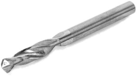
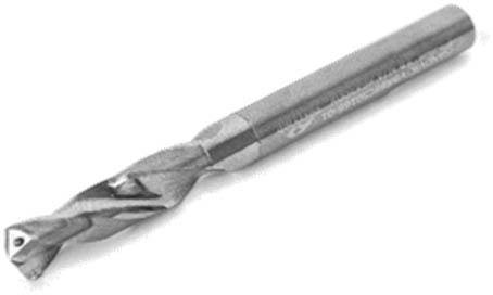
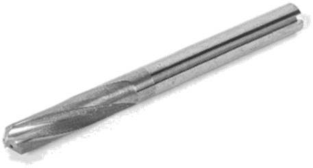
2.2 Cutting tools
Sandvik® uncoated-carbide drills with 6.0 mm diameter and cross edging were used. These are recommended for drilling CFRP, GFRP, and stacking of plates with aluminum and titanium. Table 2 presents the drill tools specifications. The drill was mounted on a 6 mm diameter collet holder in a BT-30 morse taper (DIN 6499), both manufactured by Sandvik®. The run-out (δ) was verified for each tool assembly change with a Digimess dial gauge (resolution of 0.01 mm).
Sandvik® drill tools specifications
| Series | Precorp | CoroDrill 860 | |
|---|---|---|---|
| Type | 85C | 86C | H10N |
|
|
|
|
| σ (point angle) (°) | 118 | 135 | 130 |
| Chisel edge (µm) | 73 | 93 | 120 |
| φ (helix angle) (°) | 27.6 | 26.6 | 16.6 |
| Core thickness (mm) | 1.45 | 2.11 | 1.85 |
| R a (average roughness) (µm) | 0.10 | 0.15 | 0.17 |
2.3 Experimental procedure
The experiment was carried out in a three-axis vertical machining center Romi® Discovery 308 (maximum power of 5.5 kW and maximum rotation of 4,000 rpm).
The input parameters were analyzed using three levels and combined according to the BBD, which is a method of statistical optimization that aims to change variables at three levels (−1, 0, +1) to develop a response surface. The design of experiments (DOE) consists of a combination of factor analysis and incomplete block designs [39] to reach the best levels according to the factors that influence a specific process. When three-factor, three-level BBD is used, 12 runs are required with combinations of the proposed variables, including three replicates at the center point (level 0), i.e., 15 runs. These replicates estimate the experimental variance and check the loss of linearity between the levels chosen for each variable. BBD also allows for optimization. It is based on the statistical analysis of the parameter’s influence and the nature of the result [40]. Table 3 presents the parameters used and their levels.
Three levels of input parameters
| Control factors | Level | ||
|---|---|---|---|
| (−1) | (0) | (+1) | |
| v c (m min−1) | 20 | 40 | 60 |
| f (mm rev−1) | 0.05 | 0.15 | 0.25 |
| Drill type | 86C | 85C | H10N |
The experimental design is presented in Table 4. From the definition of three control variables (input parameters), it is possible to identify four response variables (output parameters): (i) adjusted delamination factor at the tool entrance of the GFRP plate (
Response variables and control factors
| Run order | Control factors | δ (mm) | Response variables | |||||
|---|---|---|---|---|---|---|---|---|
| v c (m min−1) | f (mm rev−1) | Drill type |
|
|
|
|
||
| 1 | 60 | 0.05 | 85C | 0.01 | 1.31 | 1.45 | 103 | UNF |
| 2 | 20 | 0.05 | 85C | 0.01 | 1.07 | 1.26 | 82 | UNF |
| 3 | 60 | 0.05 | 85C | 0.01 | 1.23 | 1.34 | 138 | CRW |
| 4 | 60 | 0.15 | H10N | 0.01 | 1.51 | 1.71 | 267 | CRW |
| 5 | 40 | 0.25 | 86C | 0.02 | 1.42 | 1.89 | 371 | UNF |
| 6 | 20 | 0.15 | 86C | 0.02 | 1.39 | 1.57 | 404 | UNF |
| 7 | 40 | 0.25 | H10N | 0.01 | 1.63 | 1.91 | 235 | CRW |
| 8 | 20 | 0.05 | 85C | 0.02 | 1.24 | 1.39 | 101 | UNF |
| 9 | 40 | 0.15 | 85C | 0.02 | 1.37 | 1.61 | 369 | CRW |
| 10 | 40 | 0.15 | 85C | 0.02 | 1.30 | 1.41 | 217 | UNF |
| 11 | 40 | 0.15 | 85C | 0.02 | 1.28 | 1.40 | 240 | UNF |
| 12 | 20 | 0.15 | H10N | 0.02 | 1.47 | 1.66 | 332 | UNF |
| 13 | 40 | 0.05 | 86C | 0.02 | 1.16 | 1.42 | 337 | UNF |
| 14 | 40 | 0.05 | 86C | 0.02 | 1.35 | 1.52 | 233 | UNF |
| 15 | 60 | 0.15 | 86C | 0.02 | 1.40 | 1.58 | 223 | UNF |
| 16 | 60 | 0.15 | 86C | 0.02 | 1.38 | 1.56 | 247 | UNF |
| 17 | 60 | 0.25 | 85C | 0.01 | 1.47 | 1.72 | 378 | CRW |
| 18 | 20 | 0.25 | 85C | 0.01 | 1.55 | 1.73 | 410 | CRW |
| 19 | 20 | 0.25 | 85C | 0.01 | 1.54 | 1.72 | 370 | CRW |
| 20 | 20 | 0.15 | 86C | 0.03 | 1.49 | 1.48 | 232 | UNF |
| 21 | 60 | 0.25 | 85C | 0.02 | 1.37 | 1.69 | 335 | UNF |
| 22 | 20 | 0.15 | H10N | 0 | 1.53 | 1.79 | 341 | CRW |
| 23 | 60 | 0.15 | H10N | 0 | 1.48 | 1.93 | 328 | CRW |
| 24 | 40 | 0.25 | 86C | 0 | 1.48 | 1.83 | 362 | CRW |
| 25 | 40 | 0.15 | 85C | 0.02 | 1.34 | 1.67 | 225 | UNF |
| 26 | 40 | 0.05 | H10N | 0.01 | 1.27 | 1.58 | 107 | CRW |
| 27 | 40 | 0.25 | H10N | 0.01 | 1.70 | 1.75 | 500 | CRW |
| 28 | 40 | 0.05 | H10N | 0.01 | 1.27 | 1.61 | 114 | UNF |
| 29 | 40 | 0.15 | 85C | 0.01 | 1.40 | 1.60 | 217 | CRW |
| 30 | 40 | 0.15 | 85C | 0.01 | 1.45 | 1.83 | 240 | CRW |
*CRW, crown; UNF, uniform.
The thrust force (
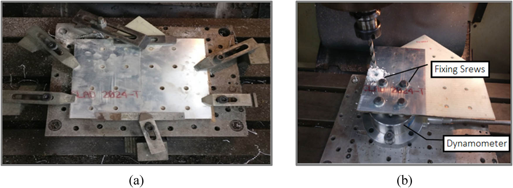
(a) Drill holes for fixing the hybrid composite plate and (b) experimental setup.
Pretests (preliminary tests) were also carried out. The positions of the holes have been optimized for maximum usage of the plates, where the minimum distance between centers was equal to 2.5
The hole images in detail were obtained using a digital microscope Dino-Lite AM-413ZT with 30x magnification after the experiment (Figure 2a). The Image-J software was used for the analysis of the holes. The treatment of tones, contrast, brightness, and formatting with a binary image filter was performed to evaluate the variables used to calculate the adjusted delamination factor (
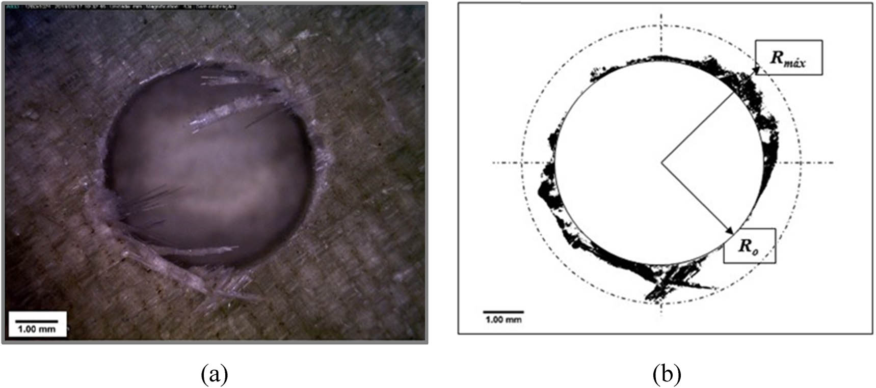
Output hole 1: (a) original image and (b) segmented image used for the calculation of
The macroscopic analysis of the burrs was performed using a portable digital microscope Dino-Lite Pro model AM-413ZT with 50x amplification used at the hole exit. Then, the types of burrs formed during the drilling process were determined. After assessing the delamination defects associated with the drilled holes, BBD methodology, which is implemented in the Minitab® 19 software, was used to analyze the influence of each input delamination parameter (
3 Results and discussion
Table 4 presents the control factors and response variables, and Figure 3 depicts the results for the response variables as a function of the control factors for the drilled holes.
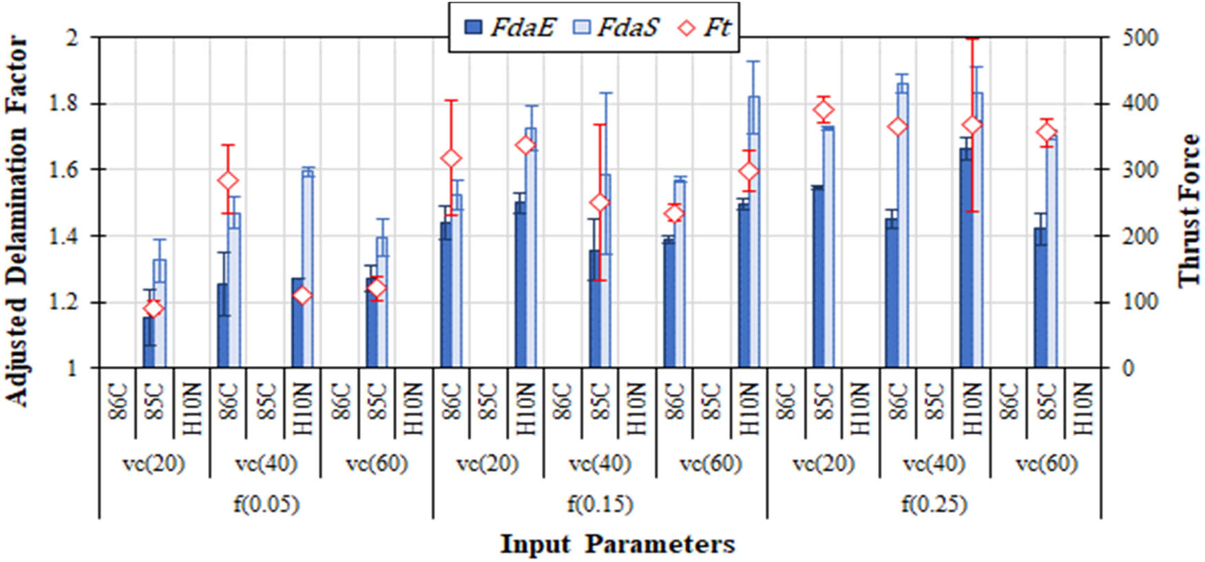
Adjusted delamination factor in the entrance and exit of the GFRP and thrust force.
The ANOVA of the response variables is presented in Table 5. Besides, for a statistical investigation through the response surface, Figure 4 presents the 3D surface plots according to the analyzed variables.
ANOVA of the response variables
| Input parameters (controllable factors) | Response variables | |||||
|---|---|---|---|---|---|---|
|
|
|
|
||||
| p-value | Contr. (%) | p-value | Contr. (%) | p-value | Contr. (%) | |
| f (mm rev−1) | <0.001 | 59.04 | <0.001 | 49.45 | <0.001 | 56.46 |
| v c (m min−1) | 0.645 | 0.15 | 0.622 | 0.35 | 0.395 | 1.19 |
| Drill | 0.003 | 7.41 | 0.026 | 8.17 | 0.534 | 0.63 |
| f × f | 0.226 | 1.68 | 0.827 | 0.17 | 0.632 | 0.59 |
| v c × v c | 0.402 | 0.22 | 0.364 | 1.84 | 0.960 | 0.01 |
| Drill × drill | 0.002 | 9.06 | 0.013 | 10.41 | 0.116 | 4.25 |
| f × v c | 0.011 | 5.25 | 0.989 | <0.01 | 0.551 | 0.58 |
| f × drill | 0.033 | 3.53 | 0.358 | 1.25 | 0.104 | 4.55 |
| v c × drill | 0.584 | 0.21 | 0.740 | 0.16 | 0.672 | 0.29 |
| R 2 | 86.2% | 71.8% | 74.3% | |||
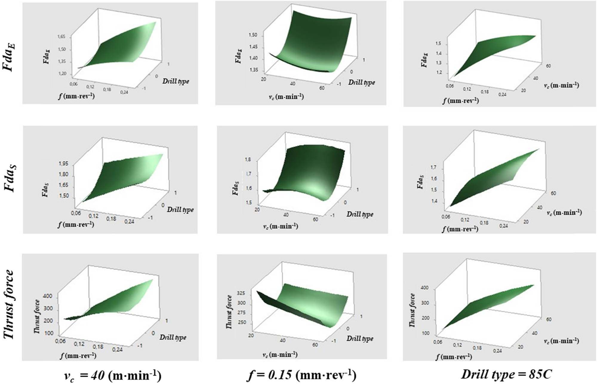
3D surface plot of response variables.
3.1 Delamination factor
The adjusted delamination factor was calculated by using image processing techniques. In Figure 3, the error bars represent the most relevant measurement variation concerning the average value. This figure shows a comparison between
The highest
These results have shown the strong influence of the feed rate on the response variables. It should also be noted that the errors associated with the output variables can be reduced by increasing the number of runs. Table 5 presents that the feed rate (f), the drill type (linear and quadratic effects), and combinations of the feed rate with the cutting speed (f × v
c) and the drill type (f × drill) have significant influence (contributions of 59.0, 16.5, 5.25, and 3.53%, respectively) on the adjusted delamination factor at the hole entrance (
Considering the adjusted delamination factor at the tool exit (
3.2 Thrust force
Concerning the analysis of the thrust force (
The 85C drill, compared to the others, has the smallest point angle (118°), which reduces the contact area of the tool-tip with the material. Likewise, its smallest core thickness (1.45 mm) combined with the smallest chisel edge (0.073 mm) contributes to the centralizing effect, reducing vibrations and resulting in less surface roughness, as shown by Astakhov [41]. Astakhov studied the roughness analysis to provide specifications of the surface quality level associated with the process qualification level. Borba et al. [48] showed that when cross sharpening is used, small chisel edge values (low effect of negative rake angle in the center of the drill) generate low
According to Kumar and Sing [3] and Wang et al. [42], thrust force (
3.3 Burrs
The burrs generated at the exit of the AA2024 plate were analyzed macroscopically, and two specific types were identified: crown (CRW) and uniform (UNF) (Figure 5). In the visual analysis, the uniform burr with drill cap (UDC) was considered a variation of the uniform burr (UNF) because they are caused by the same mechanism [43]. The hat type was not observed. As they are easier to remove, uniform burrs are preferable [33]. The UNF conditions and the absence of significant burrs were observed in 53.3% of the total holes (i.e., 1, 2, 5, 6, 8, 10, 11, 12, 13, 14, 15, 16, 20, 21, 25, and 28). In other holes, there was an undesirable CRW (46.7% of the total). The trend of better results occurred using the 86C drill with v
c ≤ 40 m min−1 and f ≤ 0.15 mm rev−1. According to Pinto [34], smaller feed rate (f) values generate lower thrust force (
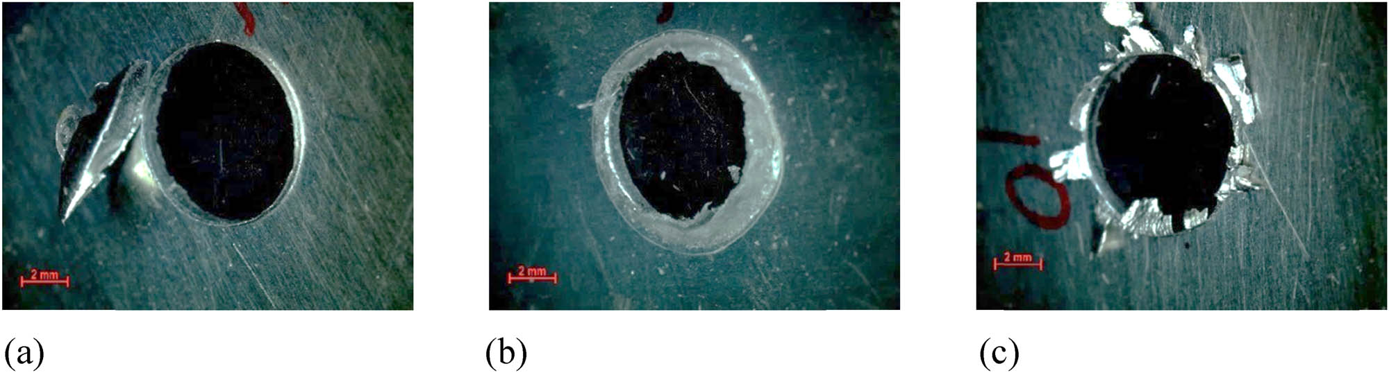
Burr types: (a) uniform (with drill cap), (b) uniform, and (c) crown.
For some sets of holes (i.e., 1, 3, 5, 12, 17, 21, 22, 24, 26, and 28), differences were observed between the burr types despite having the same cutting parameters. These demonstrate the need for additional characterization of analyzes, such as checking the burr height, microstructural analysis, and hardness analysis to quantify and classify differences in their formation. According to Ko and Lee [33] and Pinto [34], in some situations, the cutting parameters can be near to promote the transition point among the type of burr – crown and uniform – staying within the margin of error of the results. For some instances, these differences may be associated with other factors, such as holes 1 and 3, which presented close thrust force values (
The holes 9, 29, and 30 resulted in similar
Although holes 10, 11, and 25 had been made using the same cutting conditions as holes 9, 29, and 30, and obtained similar
3.4 Parameter optimization
The multivariate optimization of control variables was performed through BBD based on the response variables to minimize the delamination (tool entrance and tool exit) and thrust force simultaneously. Thus, optimized parameters were obtained such as drilling with the 85C drill applying v
c = 20 m min−1 and f = 0.05 mm rev−1, which will give the following estimated responses:
A validation test was performed using the optimized parameters obtained via BBD. Then, three holes were drilled and evaluated to check if those parameters reach the estimated responses mentioned earlier. Table 6 presents the average of the experimental results. The experimental values of
Estimated and experimented response variables
|
|
|
|
|
|---|---|---|---|
| Estimated | 1.15 | 1.36 | 90.6 |
| Experimented | 1.18 | 1.33 | 67.3 |
| Error (%) | 2.54% | 2.25% | 25.7% |
Drilling conditions: v c = 20 m min−1, f = 0.05 mm rev−1, and drill 85C.
Although the burr type was not analyzed via BBD, the optimized condition promoted a CRW type, which is not recommended for the drilling process due to the need for rework to remove this element. Figure 6 shows the images of the burrs obtained in the validation test.
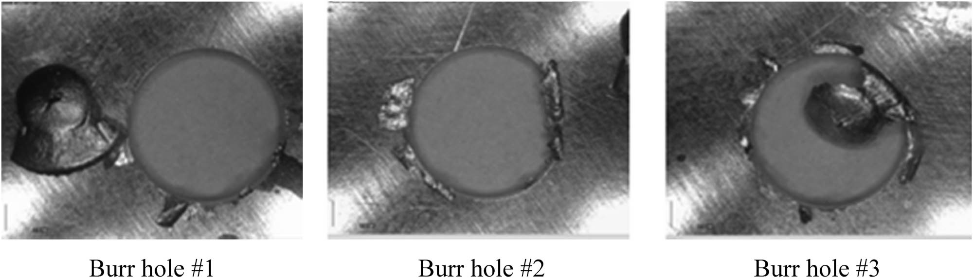
Burr holes after drilling with optimized parameters.
As commented in the literature [35,36], the UNF burrs, with less complicated removal, are associated with a distributed circular load of the holes, unlike CRW burrs, more irregular and laborious removal. The CRW type, predominant in optimization tests, is related to smaller point angles, as shown in the 85C drill (118°), and the consequent deformation in the hole center region. Silva et al. [37] recommend avoiding the deburring step because this rework leads to additional manufacturing costs, making the process unfeasible. The generation of uniform burrs with short height should be the priority goal. In most cases, this rework is carried out manually without adding value to the product.
4 Conclusion
It was evaluated the influence of cutting conditions over the delamination factor and thrust force of metal-composite laminate. The present work investigated a sandwich plate composite by AA2024/GFRP/AA2024 joint. According to the results for this specific case study, it is possible to have some relevant conclusions and, mainly, recommendations for drilling metal-composite laminates used in aeronautical joints:
The thrust force (
f and drill are control variables that influence the adjusted delamination factor significantly at the input (
The cutting speed (v c) does not affect significantly
The optimization of the cutting parameters via BBD can obtain values close to those estimated for the response variables (
In case of the burrs at the hole output of AA2024 using the optimized parameters, the results are unsatisfactory (crown type), which requires further investigations on the optimal hybrid stack drilling.
Acknowledgments
The authors thank TAP Air Portugal Co. for the donation of the AA 2024 sheets, Sandvik Coromant Co. for the donation of the uncoated drill tools, CAPES (grant 88882.346387/2019-01), and CNPq (process 310656/2018-4 and 134587/2018-9) for financial support.
-
Conflict of interest: Authors state no conflict of interest.
References
[1] Liu DF, Tang YJ, Cong WL. A review of mechanical drilling for composite laminates. Comp Struct. 2012;94(4):1265–79. 10.1016/j.compstruct.2011.11.024.Search in Google Scholar
[2] Bhagwat PM, Ramachandran M, Raichurkar P. Mechanical properties of hybrid glass/carbon fiber reinforced epoxy composites. Mater Today: Proc. 2017;4(8):7375–80. 10.1016/j.matpr.2017.07.067.Search in Google Scholar
[3] Kumar D, Sing KK. Experimental analysis of delamination, thrust force and surface roughness on drilling of glass fibre reinforced polymer composites material using different drills. Mater Today: Proc. 2017;4(8):7618–27. 10.1016/j.matpr.2017.07.095.Search in Google Scholar
[4] Xu J, El Mansori M. Experimental study on drilling mechanisms and strategies of hybrid CFRP/Ti stacks. Comp Struct. 2016;157:461–82. 10.1016/j.compstruct.2016.07.025.Search in Google Scholar
[5] Akhil KT, Shunmugesh K, Aravind S, Pramodkumar M. Optimization of drilling characteristics using grey relational analysis (GRA) in glass fiber reinforced polymer (GFRP). Mater Today: Proc. 2017;4(2, Part A):1812–9. 10.1016/j.matpr.2017.02.024.Search in Google Scholar
[6] Zitoune R, Krishnaraj V, Collombet F. Study of drilling of composite material and aluminium stack. Comp Struct. 2010;92(5):1246–55. 10.1016/j.compstruct.2009.10.010.Search in Google Scholar
[7] Ning H, Li Y, Hu N, Arai M, Takizawa N, Liu Y, et al. Experimental and numerical study on the improvement of interlaminar mechanical properties of Al/CFRP laminates. J Mater Process Technol. 2015;216:79–88. 10.1016/j.jmatprotec.2014.08.031.Search in Google Scholar
[8] Khashaba UA, El-Keran AA. Drilling analysis of thin woven glass-fiber reinforced epoxy composites. J Mater Process Technol. 2017;249:415–25. 10.1016/j.jmatprotec.2017.06.011.Search in Google Scholar
[9] Lazar M-B, Xirouchakis P. Experimental analysis of drilling fiber reinforced composites. Int J Mach Tools Manufacture. 2011;51(12):937–46. 10.1016/j.ijmachtools.2011.08.009.Search in Google Scholar
[10] Krishnaraj V, Zitoune R, Collombet F. Comprehensive review on drilling of multimaterial stacks. J Mach Form Technol. 2010; 2(3–4):171–200. https://www.researchgate.net/publication/273127359Search in Google Scholar
[11] Kihlman H, Ossbahr G, Engström M, Anderson J. Low-cost automation for aircraft assembly. Proceedings of the SAE Aerospace Manufacturing & Automated Fastening Conference & Exhibition. St. Louis, MS, USA: SAE International; 2004 Sept. 20–23. p. 8. 10.4271/2004-01-2830.Search in Google Scholar
[12] Palanikumar K. Experimental investigation and optimisation in drilling of GFRP composites. Measurement. 2011;44(10):2138–48. 10.1016/j.measurement.2011.07.023.Search in Google Scholar
[13] Zitoune R, Krishnaraj V, Collombet F, Le Roux S. Experimental and numerical analysis on drilling of carbon fibre reinforced plastic and aluminium stacks. Comp Struct. 2016;146:148–58. 10.1016/j.compstruct.2016.02.084.Search in Google Scholar
[14] Davim JP, editor. Machining composites materials. London: John Wiley & Sons; 2013.Search in Google Scholar
[15] Kumar D, Singh K. Investigation of delamination and surface quality of machined holes in drilling of multiwalled carbon nanotube doped epoxy/carbon fiber reinforced polymer nanocomposite. Proc Inst Mech Eng, Part L: J Mater: Des Appl. 2017;233(4):647–63. 10.1177/1464420717692369.Search in Google Scholar
[16] Silva JA. Analysis of drilling glass-fiber reinforced polyester composite Thesis (M.Sc.) in Mechanical Engineering. Florianópolis. SC, Brazil: POSMEC-UFSC; 2015. p. 117. (in Portuguese). https://repositorio.ufsc.br/xmlui/handle/123456789/160729Search in Google Scholar
[17] Ho-Cheng H, Dharan CKH. Delamination during drilling in composite laminates. J Eng Ind (Trans ASME). 1990;112(3):236–9. 10.1115/1.2899580.Search in Google Scholar
[18] Davim JP, Rubio JC, Abrão AM. A novel approach based on digital image analysis to evaluate the delamination factor after drilling composite laminates. Compos Sci Technol. 2007;67(9):1939–45. 10.1016/j.compscitech.2006.10.009.Search in Google Scholar
[19] Velaga M, Cadambi RM. Drilling of GFRP composites for minimising delamination effect. Mater Today: Proc. 2017;4(10):11229–36. 10.1016/j.matpr.2017.09.044.Search in Google Scholar
[20] Rakesh PK, Singh I, Kumar D. Flexural behaviour of glass fibre-reinforced plastic laminates with drilled hole. Proc Inst Mech Eng, Part L: J Mater: Des Appl. 2012;226(2):149–58. 10.1177/1464420711430007.Search in Google Scholar
[21] Malacarne DK, Devitte C, Souza AJ. Drilling parameters optimization for quality holes in GFRP via Box-Behnken Design. Annals of the 10th Brazilian Congress of Manufacturing Engineering. São Carlos, SP, Brazil: ABCM; 2019 Aug. 5–7. p. 5. (in Portuguese). https://www.researchgate.net/publication/335507306Search in Google Scholar
[22] Durão LMP, Gonçalves DJS, Albuquerque VHC, Tavares JMRS. Evaluation of tools for drilling laminates. Annals of the 8th National Congress of Experimental Mechanics. Guimarães, Portugal: APAET; 2010 April 21–23. p. 10. (in Portuguese). https://www.researchgate.net/publication/261834447Search in Google Scholar
[23] Feito N, Álvarez JD, Álvarez AD, Cantero JL, Miguélez MH. Experimental analysis of the influence of drill point angle and wear on the drilling of woven CFRPs. Mater (Basel). 2014;7(6):4258–71. 10.3390/ma7064258.Search in Google Scholar PubMed PubMed Central
[24] Karimi NZ, Heidary H, Ahmadi M. Residual tensile strength monitoring of drilled composite materials by acoustic emission. Mater Des. 2012;40:229–36. 10.1016/j.matdes.2012.03.040.Search in Google Scholar
[25] Srinivasan T, Palanikumar K, Rajagopal K, Latha B. Optimization of delamination factor in drilling GFR-polypropylene composites. Mater Manuf Process. 2017;32(2):226–33. 10.1080/10426914.2016.1151038.Search in Google Scholar
[26] Batista MF, Rodrigues AR, Basso IF, Toti FA, Oliveira FB. Method for assessing hole damages in composites materials. Annals of the 9th Brazilian Congress of Manufacturing Engineering. Joinville, SC, Brazil: ABCM; 2017 July 26–29. p. 9. https://www.researchgate.net/publication/31999562910.26678/ABCM.COBEF2017.COF2017-0521Search in Google Scholar
[27] Gaitonde V, Karnik SR, Rubio JC, Correia AE, Abrao AM, Davim JP. Analysis of parametric influence on delamination in high-speed drilling of carbon fiber reinforced plastic composites. J Mater Process Technol. 2008;203(1–3):431–8. 10.1016/j.jmatprotec.2007.10.050.Search in Google Scholar
[28] Davim JP, Reis P, Antonio CC. Experimental study of drilling glass fiber reinforced plastics (GFRP) manufactured by hand lay-up. Compos Sci Technol. 2004;64(2):289–97. 10.1016/S0266-3538(03)00253-7.Search in Google Scholar
[29] Rubio JC, Silva LR, Abrão AM, Faria PE, Correia AE, Davim JP. Furação com alta velocidade de corte em compósitos poliméricos reforçados com fibras de vidro. Ciência Tecnol dos Materiais. 2007;19(3–4):83–7. http://www.scielo.mec.pt/pdf/ctm/v19n3-4/19n3-4a10.pdfSearch in Google Scholar
[30] Davim JP, Reis P. Study of delamination in drilling carbon fiber reinforced plastics (CFRP) using design experiments. Comp Struct. 2003;59(4):481–7. 10.1016/S0263-8223(02)00257-X.Search in Google Scholar
[31] Abrão AM, Rubio JC, Faria PE, Davim JP. The effect of cutting tool geometry on thrust force and delamination when drilling glass fibre reinforced plastic composite. Mater Des. 2008;29(2):508–13. 10.1016/j.matdes.2007.01.016.Search in Google Scholar
[32] Rubio JC, Abrao AM, Faria PE, Correia AE, Davim JP. Effects of high speed in the drilling of glass fibre reinforced plastic: evaluation of the delamination factor. Int J Mach Tools Manuf. 2008;48(6):715–20. 10.1016/j.ijmachtools.2007.10.015.Search in Google Scholar
[33] Ko S-L, Lee J-K. Analysis on burr formation in drilling with new concept drill. J Mater Process Technol. 2001;113(1–3):392–8. 10.1016/S0924-0136(01)00717-8.Search in Google Scholar
[34] Pinto GTB. Influence Spec drill geometry Drill aeronautical thin-sheets Thesis (M.Sc.) in Mechanical Engineering. Florianópolis. SC, Brazil: POSMEC-UFSC; 2010; p. 164. (in Portuguese). http://repositorio.ufsc.br/xmlui/handle/123456789/93674Search in Google Scholar
[35] Ko S-L, Chang J-E, Yang G-E. Burr minimizing scheme in drilling. J Mater Process Technol. 2003;140(1–3):237–42. 10.1016/S0924-0136(03)00719-2.Search in Google Scholar
[36] Ballou JR, Joshi SS, DeVor RE, Kapoor SG. Burr formation in drilling intersecting holes with machinable austempered ductile iron (MADITM). J Manuf Process. 2007;9(1):35–46. 10.1016/S1526-6125(07)70106-8.Search in Google Scholar
[37] Silva JD, Saramago SFP, Machado AR. Optimization of the cutting conditions (Vc, fz e doc) for burr minimization in face milling of mould steel. J Brazillian Soc Mech Sci Eng. 2009;31(2):151–60. 10.1590/S1678-58782009000200008.Search in Google Scholar
[38] Paiva JMF, Mayer S, Cândido G, Rezende MC. Evaluation of glass transition temperature of the repaired polymeric composites of aeronautical use. Polímeros. 2006;16(1):79–87. (in Portuguese). 10.1590/S0104-14282006000100016.Search in Google Scholar
[39] Garcia RF, Feix EC, Mendel HT, Gonzalez AR, Souza AJ. optimization of cutting parameters for finish turning of 6082-T6 aluminum alloy under dry and RQL conditions. J Braz Soc Mech Sci Eng. 2019;41(A):317. 10.1007/s40430-019-1826-4.Search in Google Scholar
[40] Ferreira SLC, Bruns RE, Silva EGP, Santos WNL, Quintella CM, David JM, et al. Statistical designs and response surface techniques for the optimization of chromatographic systems. J Chromatogr A. 2007;1158(1–2):2–14. 10.1016/j.chroma.2007.03.051.Search in Google Scholar
[41] Astakhov VP. Geometry of single-point turning tools and drills: fundamentals and practical applications. London: Springer-Verlag; 2010. 10.1007/978-1-84996-053-3.Search in Google Scholar
[42] Wang C-Y, Chen Y-H, An Q-L, Cai X-J, Ming W-W, Chen M. Drilling temperature and hole quality in drilling of CFRP/aluminum stacks using diamond coated drill. Int J Precis Eng Manuf. 2015;16(8):1689–97. 10.1007/s12541-015-0222-y.Search in Google Scholar
[43] Aurich JC, Dornfeld D, Arrazola PJ, Franke V, Leitz L, Min S. Burrs – analysis, control and removal. CIRP Ann. 2009;58(2):519–42. 10.1016/j.cirp.2009.09.004.Search in Google Scholar
[44] Dornfeld DA, Kim JS, Dechow H, Hewson J, Chen LJ. Drilling burr formation in titanium alloy Ti-6Al-4V. CIRP Ann. 1999;48(1):73–6. 10.1016/S0007-8506(07)63134-5.Search in Google Scholar
[45] Manjunatha NN. ANN Model Predict Burr Height Thickness Thesis (M.Sc.). Kansas, USA: Department of Industrial and Manufacturing Engineering, Graduate School of Wichita State University; 2007; p. 101. http://hdl.handle.net/10057/1147Search in Google Scholar
[46] Durão LMP, Gonçalves DJS, Tavares JMRS, Albuquerque VHC, Marques AT. Comparative analysis of drills for composite laminates. J Comp Mater. 2012;46(14):1649–59. 10.1177/0021998311421690.Search in Google Scholar
[47] Tsao CC, Hocheng H. The effect of chisel length and associated pilot hole on delamination when drilling composite materials. Int J Mach Tools Manuf. 2003;43(11):1087–92. 10.1016/S0890-6955(03)00127-5.Search in Google Scholar
[48] Borba RB, Ribeiro Filho SLM, Brandão LC. Influence of different types of sharpening in straight flute drills on burr formation. Acta Sci Technol. 2016;38(4):465–8. 10.4025/actascitechnol.v38i4.29222.Search in Google Scholar
© 2021 Cristiano Devitte et al., published by De Gruyter
This work is licensed under the Creative Commons Attribution 4.0 International License.
Articles in the same Issue
- Effects of Material Constructions on Supersonic Flutter Characteristics for Composite Rectangular Plates Reinforced with Carbon Nano-structures
- Processing of Hollow Glass Microspheres (HGM) filled Epoxy Syntactic Foam Composites with improved Structural Characteristics
- Investigation on the anti-penetration performance of the steel/nylon sandwich plate
- Flexural bearing capacity and failure mechanism of CFRP-aluminum laminate beam with double-channel cross-section
- In-Plane Permeability Measurement of Biaxial Woven Fabrics by 2D-Radial Flow Method
- Regular Articles
- Real time defect detection during composite layup via Tactile Shape Sensing
- Mechanical and durability properties of GFRP bars exposed to aggressive solution environments
- Cushioning energy absorption of paper corrugation tubes with regular polygonal cross-section under axial static compression
- An investigation on the degradation behaviors of Mg wires/PLA composite for bone fixation implants: influence of wire content and load mode
- Compressive bearing capacity and failure mechanism of CFRP–aluminum laminate column with single-channel cross section
- Self-Fibers Compacting Concrete Properties Reinforced with Propylene Fibers
- Study on the fabrication of in-situ TiB2/Al composite by electroslag melting
- Characterization and Comparison Research on Composite of Alluvial Clayey Soil Modified with Fine Aggregates of Construction Waste and Fly Ash
- Axial and lateral stiffness of spherical self-balancing fiber reinforced rubber pipes under internal pressure
- Influence of technical parameters on the structure of annular axis braided preforms
- Nano titanium oxide for modifying water physical property and acid-resistance of alluvial soil in Yangtze River estuary
- Modified Halpin–Tsai equation for predicting interfacial effect in water diffusion process
- Experimental research on effect of opening configuration and reinforcement method on buckling and strength analyses of spar web made of composite material
- Photoluminescence characteristics and energy transfer phenomena in Ce3+-doped YVO4 single crystal
- Influence of fiber type on mechanical properties of lightweight cement-based composites
- Mechanical and fracture properties of steel fiber-reinforced geopolymer concrete
- Handcrafted digital light processing apparatus for additively manufacturing oral-prosthesis targeted nano-ceramic resin composites
- 3D printing path planning algorithm for thin walled and complex devices
- Material-removing machining wastes as a filler of a polymer concrete (industrial chips as a filler of a polymer concrete)
- The electrochemical performance and modification mechanism of the corrosion inhibitor on concrete
- Evaluation of the applicability of different viscoelasticity constitutive models in bamboo scrimber short-term tensile creep property research
- Experimental and microstructure analysis of the penetration resistance of composite structures
- Ultrasensitive analysis of SW-BNNT with an extra attached mass
- Active vibration suppression of wind turbine blades integrated with piezoelectric sensors
- Delamination properties and in situ damage monitoring of z-pinned carbon fiber/epoxy composites
- Analysis of the influence of asymmetric geological conditions on stability of high arch dam
- Measurement and simulation validation of numerical model parameters of fresh concrete
- Tuning the through-thickness orientation of 1D nanocarbons to enhance the electrical conductivity and ILSS of hierarchical CFRP composites
- Performance improvements of a short glass fiber-reinforced PA66 composite
- Investigation on the acoustic properties of structural gradient 316L stainless steel hollow spheres composites
- Experimental studies on the dynamic viscoelastic properties of basalt fiber-reinforced asphalt mixtures
- Hot deformation behavior of nano-Al2O3-dispersion-strengthened Cu20W composite
- Synthesize and characterization of conductive nano silver/graphene oxide composites
- Analysis and optimization of mechanical properties of recycled concrete based on aggregate characteristics
- Synthesis and characterization of polyurethane–polysiloxane block copolymers modified by α,ω-hydroxyalkyl polysiloxanes with methacrylate side chain
- Buckling analysis of thin-walled metal liner of cylindrical composite overwrapped pressure vessels with depressions after autofrettage processing
- Use of polypropylene fibres to increase the resistance of reinforcement to chloride corrosion in concretes
- Oblique penetration mechanism of hybrid composite laminates
- Comparative study between dry and wet properties of thermoplastic PA6/PP novel matrix-based carbon fibre composites
- Experimental study on the low-velocity impact failure mechanism of foam core sandwich panels with shape memory alloy hybrid face-sheets
- Preparation, optical properties, and thermal stability of polyvinyl butyral composite films containing core (lanthanum hexaboride)–shell (titanium dioxide)-structured nanoparticles
- Research on the size effect of roughness on rock uniaxial compressive strength and characteristic strength
- Research on the mechanical model of cord-reinforced air spring with winding formation
- Experimental study on the influence of mixing time on concrete performance under different mixing modes
- A continuum damage model for fatigue life prediction of 2.5D woven composites
- Investigation of the influence of recyclate content on Poisson number of composites
- A hard-core soft-shell model for vibration condition of fresh concrete based on low water-cement ratio concrete
- Retraction
- Thermal and mechanical characteristics of cement nanocomposites
- Influence of class F fly ash and silica nano-micro powder on water permeability and thermal properties of high performance cementitious composites
- Effects of fly ash and cement content on rheological, mechanical, and transport properties of high-performance self-compacting concrete
- Erratum
- Inverse analysis of concrete meso-constitutive model parameters considering aggregate size effect
- Special Issue: MDA 2020
- Comparison of the shear behavior in graphite-epoxy composites evaluated by means of biaxial test and off-axis tension test
- Photosynthetic textile biocomposites: Using laboratory testing and digital fabrication to develop flexible living building materials
- Study of gypsum composites with fine solid aggregates at elevated temperatures
- Optimization for drilling process of metal-composite aeronautical structures
- Engineering of composite materials made of epoxy resins modified with recycled fine aggregate
- Evaluation of carbon fiber reinforced polymer – CFRP – machining by applying industrial robots
- Experimental and analytical study of bio-based epoxy composite materials for strengthening reinforced concrete structures
- Environmental effects on mode II fracture toughness of unidirectional E-glass/vinyl ester laminated composites
- Special Issue: NCM4EA
- Effect and mechanism of different excitation modes on the activities of the recycled brick micropowder