Active vibration suppression of wind turbine blades integrated with piezoelectric sensors
-
Sang-Lae Lee


Abstract
As the wind turbine size gets larger, the optimal design of blades, which is a major source of energy for the wind turbines and also the cause of loads, is becoming more important than anything else. Therefore, reducing the load on the blade should be the top priority in designing a blade. In this article, we studied the vibration control of the stiffened wind blades subjected to a wind load with piezoelectric sensors and actuators to mitigate fluctuations in loading and adding damping to the blade. The model is a laminated composite blade with a shear web and the PZT piezomaterial layers embedded on the top and bottom surfaces act as a sensor and actuator, respectively. A uniformly distributed external wind load is assumed over the entire plate surface for simplicity. The first-order shear deformation (FSDT) theory is adopted, and Hamilton’s principle is used to derive the finite element equation of motion. The modal superposition technique and the Newmark-
Nomenclature
-
-
element nodal displacement vector of a plate
-
-
element nodal displacement vector of
-
-
thickness of the piezoelectric actuator layer
-
-
resultant force of a plate
-
-
resultant moment of a plate
-
-
actuating voltage
-
-
resultant axial stress of the
- M xs
-
resultant bending stress of the
-
-
resultant shear stress of the
-
-
modal displacement vector
-
-
state-space variable
-
-
modal matrix with
-
-
system matrix in a state-space form
-
-
control matrix in a state-space form
-
-
disturbance matrix in a state-space form
-
-
shear-web location parameter
-
-
plate element
-
-
-
-
1 Introduction
A wind turbine blade is a complex engineering system, subjected to highly fluctuating and irregular loads. These vibrations can cause catastrophic damages due to structural fatigue and progressive failure of the lightweight structure, resulting in unexpected maintenances, reduced efficiency and shortened lifetime. To improve the reliability of such lightweight structures, several techniques were used, both experimentally and numerically, to either limit or change the vibration responses of such systems. With the recent developments in the sensor–actuator technologies and in smart materials, especially piezoelectric materials, an active vibration control has been utilized for vibration suppression. The piezoelectric sensors are used to detect and quantify the mechanical stress applied to the materials. This is due to the direct piezoelectric effect, wherein the material generates a certain amount of electric charge when subjected to physical deformation. Actuators, on the other hand, operate in the opposite direction. Rather than generating electric charges, when given a certain amount of electrical energy, the material undergoes mechanical deformation due to the converse piezoelectric effect. These two flexible effects, coupled with the economic availability of the piezoelectric materials and the ease with which they can be bonded to other materials, make the popularity of piezoelectric materials well justified.
In past years, a number of issues related to nonlinear aero-elastic modeling and active vibration control based on piezoelectric actuation were investigated. The vibration control of a thin-walled beam integrated with piezoelectric fiber composites and the modeling and nonlinear vibration analysis of anisotropic laminated cylindrical shells or plates with the piezoelectric fiber-reinforced composite actuators were analyzed [1,2,3,4,5,6,7,8]. St-Amant and Cheng [9] studied the simulations and experiments for the active vibration control of a plate with integrated piezoceramics. Balamurugan and Marayanan [10] investigated the mechanics and the coupled analysis of the piezo-laminated plate and curvilinear shell structures and their vibration control performance. Mukherjee et al. [11] studied the active vibration control of stiffened plates using piezoelectric effects. Based on the finite element method, Sadek and Tawfik [12] developed a refined higher-order displacement model for the analysis of concentrically and eccentrically stiffened laminated plates. The aerothermoelastic characteristics of a supersonic laminated cylindrical shell and the active flutter control of the aeroelastic structure using piezoelectric materials were analyzed by Song and Li [13]. Shen and Yang [14] dealt with small- and large-amplitude flexural vibrations of anisotropic shear-deformable laminated cylindrical shells with the piezoelectric fiber-reinforced composite actuators in thermal environments.
Meanwhile, many studies have been conducted on various types of beam models made of composite materials. Mirzaei et al. [15,16,17] investigated the functionally graded (FG) simple beam model using first-order shear deformation theory. Arefi and Zenkour [18,19] studied the transient analysis of a three-layer microbeam based on higher-order sinusoidal shear deformation theory. Kiani [20] studied the torsional vibration of FG carbon nanotube-reinforced conical shells. Jalaei and Civalek [21] examined the dynamic instability of the magnetically embedded viscoelastic porous FG nanobeam. Civalek et al. [22,23] dealt with the static stability and vibration analysis of microbeams.
In addition, various load-reduction studies using piezoelectric actuation were conducted in the wind blade field as well. Liu [24] investigated the classical flutter and flutter suppression of a composite wind blade beam composed of a single-cell thin-walled structure and an embedded piezoelectric patch. Using piezoelectric actuation on the wind blade, active control of classical flutter suppression was studied. Abdelrahman et al. [25] used an active vibration control method, numerically, for the vibration suppression of a wind turbine blade model, with a piezoelectric sensor and actuator. The effects of the piezoelectric size and the piezoelectric material properties on the vibration response were investigated. Hulskamp et al. [26] designed and constructed a scaled smart rotor, equipped with trailing-edge flaps, to study its fatigue load reduction potentials. The flaps were based on the piezoelectric thunder actuators, and the dynamic strain behavior of the blade was analyzed for the optimal placement of the sensors.
This article presents the investigation of the active vibration control of a stiffened laminated wind blade with piezoelectric materials under an external load. A study is conducted on how to reduce the load in an active way using a piezoelectric material when an external excessive load is applied to the wind turbine blade. This study provides a way for vibration suppression and active control of a wind turbine blade based on the piezoelectric actuation with an optimal shear-web location.
2 Stiffened laminated plate with piezoelectrics
The wind turbine blade is a load-carrying aerodynamic structure, which consists of suction and pressure aerodynamic shells, skin, spar cap and the shear webs, as shown in Figure 1. The skin requires the blade exterior to withstand the torsion load. Thus, it is a sandwich structure composed of bi-axle or tri-axle (2AX or 3AX) glass fibers and foam material. The foam material is used to enhance flexural stiffness and prevent buckling, and PVC foam or balsa wood is mainly used. Spar caps are inserted into the thick beams by stacking dozens of thin unidirectional fibers, which withstand most of the bending moment that occurs due to the wind load. The shear web is located between the skins. It has a sandwich structure consisting of bi-axle glass fiber and foam to withstand the transverse shear load. For the wind turbine blades, the spar cap enables the blade to be structurally robust under a wind load. Additionally, the shear webs support the spar caps that play this role, and the positioning of the shear webs and the optimization of the spar caps are one of the most important factors in designing blades.
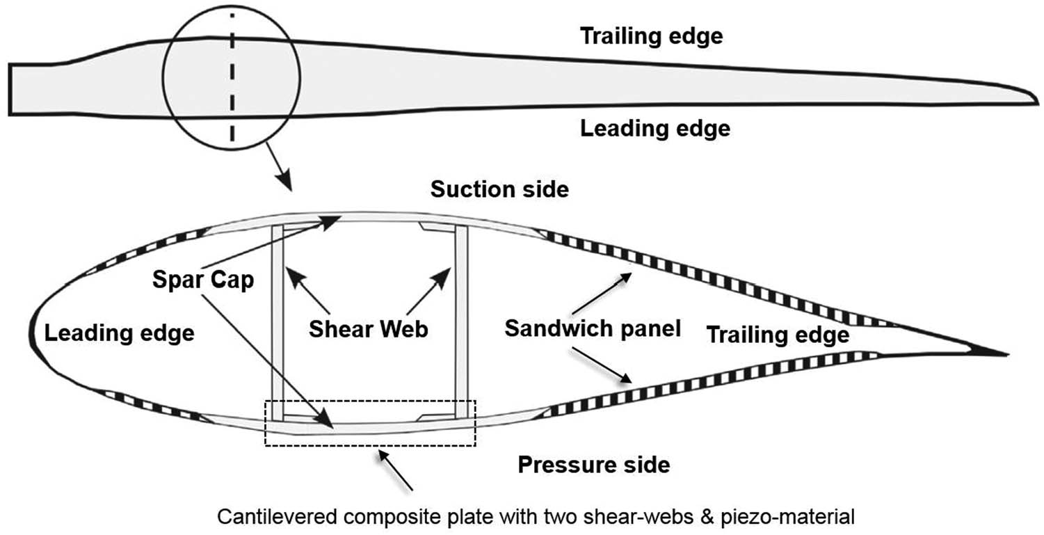
Cross-section of a wind turbine blade.
Considering these structural characteristics of the blade, a laminated composite plate, reinforced with a shear web in which a piezoelectric patch is embedded, which simplifies the spar cap area of the blades for various calculations, was used for this calculation, as shown in Figure 2. For various case studies and calculations, the wind turbine blade is replaced by a simplified rectangular model, composed of PZT piezo-material layers embedded on the top and bottom surfaces to act as a sensor and actuator, respectively. For simplicity, a uniform external load is assumed to be distributed over the entire plate surfaces and the shear webs are assumed to be placed parallel to the geometric coordinates
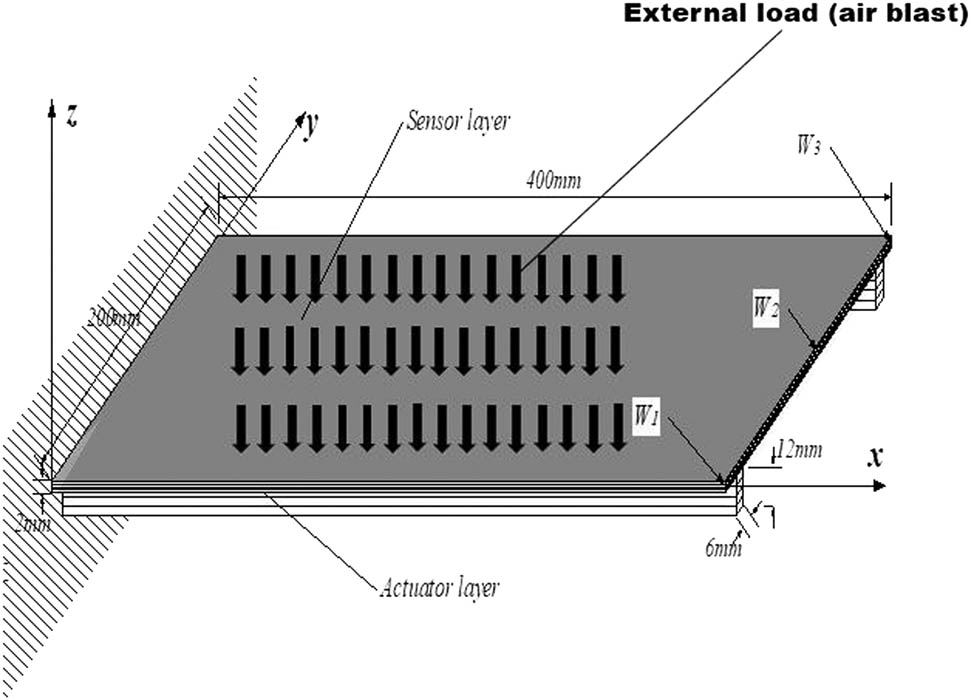
Cantilevered composite plate with two shear webs, piezoelectric sensors and actuators.
2.1 Constitutive equations
Linear piezoelectric coupling for the kth layer between the elastic field and the electric field can be expressed by “direct” and “converse” piezoelectric equations, respectively.
The direct piezoelectric effect is given by
whereas the converse piezoelectric effect is given by
In equations (1) and (2),
2.2 Finite element formulations
A stiffened plate is composed of a plate with a number of shear webs, and the members are assumed to be made up of laminated composites. In this section, a finite element formulation is adopted by using a nine-node plate element with three-node beam elements.
Using the first-order shear deformation plate theory (FSDPT), the displacement fields
where subscript p denotes plate. Furthermore,
Then, the strain fields of the plate are expressed as a function of the nodal displacement variables, such as
where subscripts m, b, and s denote the membrane strain, bending strain and shear strain, respectively. Furthermore,
The displacement fields for the
where subscripts
where
Additionally, the conditions of displacement compatibility between the plate and the
where
Using a transformation matrix
Then, applying the extended Hamilton’s principle,
where
First, the total kinetic energy is given by
where
Next, the total potential energy is given by
Finally, the work done by external forces is
where
On the other hand, the electric field vector,
where
Substituting equations (10)–(12) into equation (9) and considering the Rayleigh damping, the equation of motion can be obtained as
where
Additionally,
The damping matrix
Also, a sensor patch is assumed to cover several elements, and the closed circuit charge measured through the electrodes of a sensor patch in the
where an electric displacement in the thickness direction
The sensor voltage is computed as follows:
where
where
Substituting equation (19) into equation (14) and assembling the element equations gives the global dynamic equation,
2.3 Control algorithm
The constant gain negative velocity feedback control algorithm is used as a control algorithm. The formula for element equations of motion is as follows:
If the piezoelectric layer is used as an actuator, we have
where
In the case of the sensing voltage,
In equation (21), the stiffness matrix term
Finally, the actuating voltage is summarized as
2.4 Shear web location
With regard to the location of a shear web, two stiffeners are placed at the same distance (
where
Additionally, the displacements are defined as follows [8]:
where
2.5 External Load
To study the effects of the piezoelectric actuation and the shear-web location, an external aerodynamic force is applied to the structural model. To simulate the effects of the extreme loading conditions, a blast load is adopted, as shown in Figure 3. It is characterized by an abrupt pressure increase at the shock front, followed by a quasi-exponential decay back to ambient pressure. A negative phase follows, in which the pressure is less than the ambient (
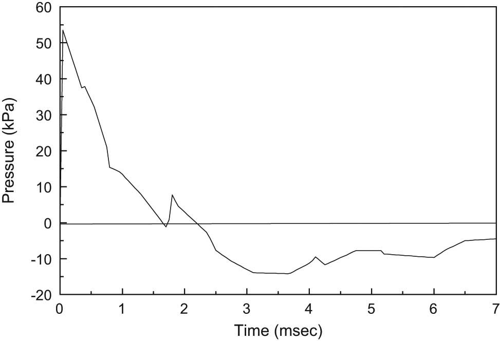
Time variation of average pressure due to air blast on a square plate.
The variation of the total pressure is given by the Friedlander decay function [28] as
where
3 Numerical simulations and discussion
In this study, a stiffened plate with piezoelectric sensors and actuators subjected to blast loading is considered. The numerical results of the effect of the piezoelectric material and the shear-web location are discussed. The wind turbine blade is replaced by a simplified rectangular model as shown in Figure 2, a cantilever laminated composite plate with two shear webs in the x-direction. The plate is bonded at the upper and lower surfaces by piezomaterials, and two shear webs are installed under the plate to reduce the load. For simplicity, a uniform external load is assumed to be distributed over the entire plate surface. The upper and lower piezoelectric layers are assumed as sensor and actuators, respectively. The dimension of the plate is
Material properties [29]
| Properties | PZT piezomaterial | T300/976 |
|---|---|---|
| Young’s modulus (GPa):
|
63.0 | 150 |
|
|
63.0 | 9.0 |
| Poisson’s ratio:
|
0.3 | 0.3 |
|
|
0.3 | 0.3 |
| Shear modulus (GPa):
|
24.2 | 7.10 |
|
|
24.2 | 2.50 |
| Density (
|
7,600 | 1,600 |
| Piezoelectric coefficients (pC/N):
|
−171 | — |
|
|
374 | — |
| Relative permittivity (
|
1,700 | — |
| Electromechanical coupling factor (k):
|
0.34 | — |
|
|
0.7 | — |
As a control algorithm, a constant gain negative velocity feedback control algorithm is used. A modal superposition method is applied in the analysis by considering the first eight modes, and the initial damping ratio for each of the modes is assumed as 0.7%. The Newmark-
3.1 Code verification
To verify the numerical model in this study, the results are compared with the previous data. The first case is a cantilevered laminated composite plate with a size
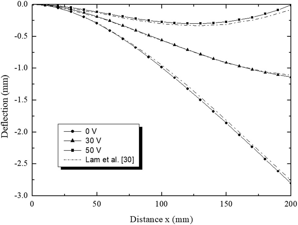
The centerline deflection under uniform load and different actuator’s input voltage.
As for the second case, the result is the deflection response of a square plate subjected to an air blast. The size of the plate model is
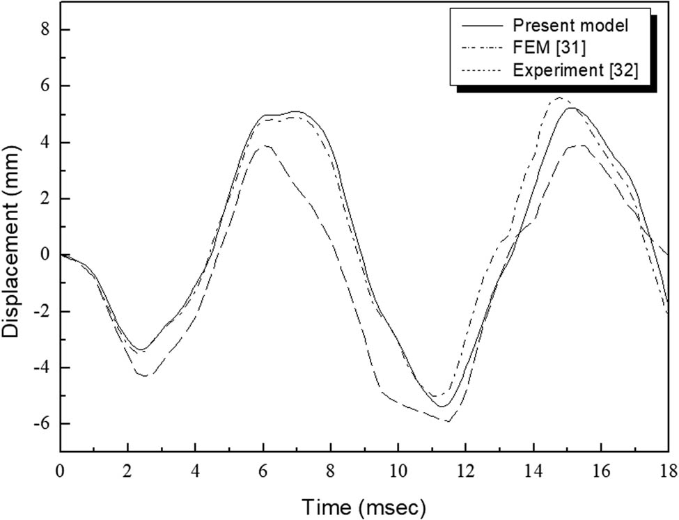
Displacement-time response of the center of the square plate subjected to air blast.
The last case is a glass-reinforced polyester plate with a centrally placed shear web [11]. The two opposite edges are free and the other two edges are clamped. The dimensions of the plate are
Comparison of natural frequencies (Hz) of stiffened plate
| Mode no. | Ref. [11] | Ref. [33] | Present | Discrepancy (%) | |
|---|---|---|---|---|---|
| With Ref. [11] | With Ref. [33] | ||||
| 1st | 68.47 | 68.61 | 68.13 | 0.5 | 0.7 |
| 2nd | 68.66 | 71.20 | 68.77 | −0.2 | 3.5 |
| 3rd | 119.59 | 124.70 | 117.55 | 1.7 | 6.1 |
| 4th | 162.16 | 150.40 | 160.12 | 1.3 | −6.1 |
| 5th | 177.11 | 183.20 | 177.45 | −0.2 | 3.2 |
| 6th | 177.39 | 184.80 | 178.31 | −0.5 | 3.6 |
| 7th | 266.58 | 251.90 | 262.58 | 1.5 | −4.1 |
As shown above, the code used in this calculation corresponds well with the references, and various calculations are performed using this code.
3.2 Vibration suppression of plates with stiffeners under a blast load
The stiffened plate models with three types of shear-web locations are shown in Figure 6. As mentioned in Section 2.3 in detail, various studies were conducted on the behavior of a plate according to the location of the shear web and its control algorithms. In the case of
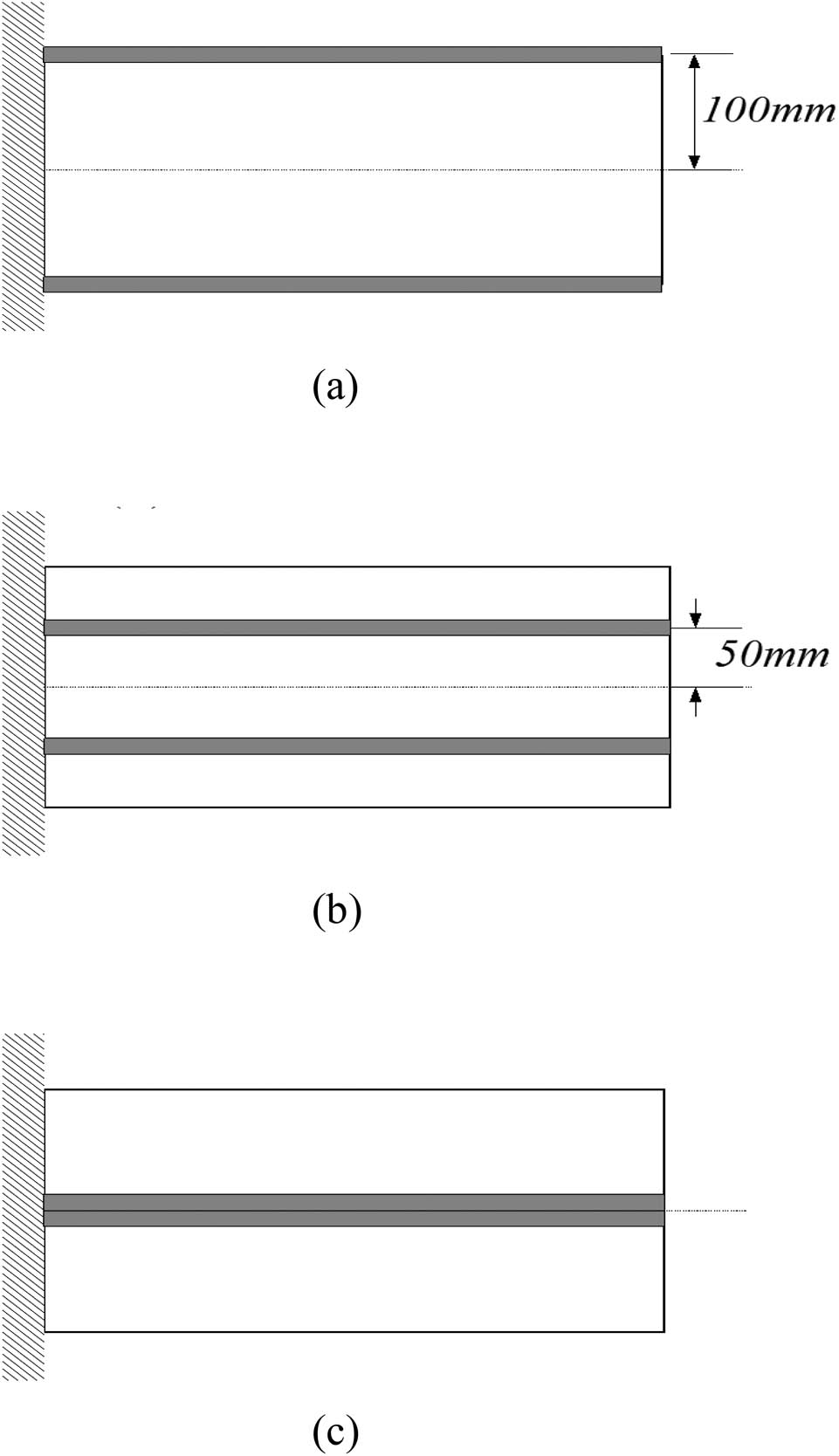
Three cases of shear-web location: (a) case 1, (b) case 2 and (c) case 3.
3.2.1 Effect of the shear-web locations
The effect of a shear-web location is investigated. Two shear webs are placed at the same distance from the centerline along the width of a plate. In addition, the piezoelectric sensors and actuators are distributed over the entire plate surface. Under these conditions, the modal analysis is performed and the results are shown in Table 3, which lists the first six natural frequencies of the stiffened plate under different cases: case 1 (
Natural frequencies of different shear-web cases
| Mode no. | Case 1 (
|
Case 2 (
|
Case 3 (
|
|---|---|---|---|
| 1st | 67.6 | 91.4 | 39.6 |
| 2nd | 117.7 | 92.4 | 78.7 |
| 3rd | 155.3 | 205.2 | 133.6 |
| 4th | 212.1 | 294.7 | 178.3 |
| 5th | 290.4 | 337.2 | 214.4 |
| 6th | 379.4 | 450.2 | 273.3 |
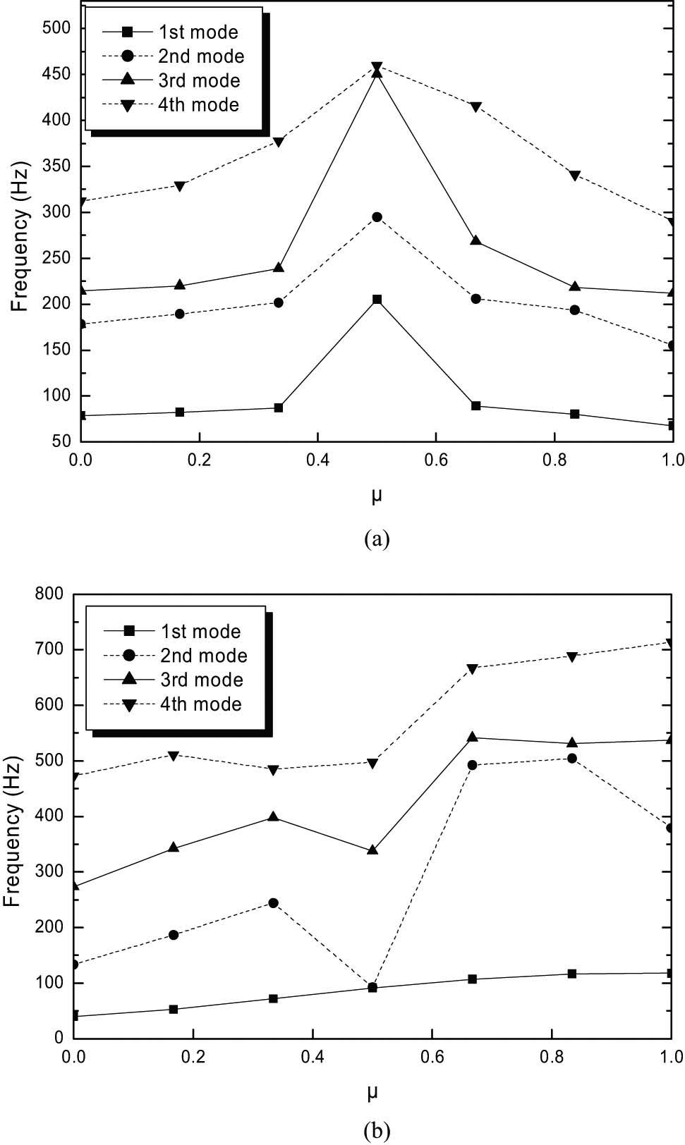
Natural frequencies for different shear-web locations: (a) bending modes and (b) twisting modes.
In addition, at a specific constant gain (G = 3,000), the response comparison such as vertical displacement, transverse bending and lateral twisting with three shear-web cases are shown in Figure 8. The controlled displacements of the shear-web case 1 are damped out more effectively when compared to the shear-web cases 2 and 3; however, a peak vertical displacement appeared in the shear-web case 1. Moreover, the transverse bending of the shear-web cases 1, 2 and 3 show the same tendency as with the vertical displacement; however, an effective vibration control can be performed for the shear-web case 2. The lateral twisting of the shear-web case 1 is most effective, as compared to other cases. Therefore, when determining the optimum shear-web position, considering the characteristics of the load direction acting on the wind turbine blades is more important.

Response comparison of the three shear-web cases (gain = 3,000): (a) vertical displacement, (b) transverse bending and (c) lateral twisting.
3.2.2 Effect of a control gain
To investigate the effect of a control gain with various shear-web locations on control performance, typical configurations (
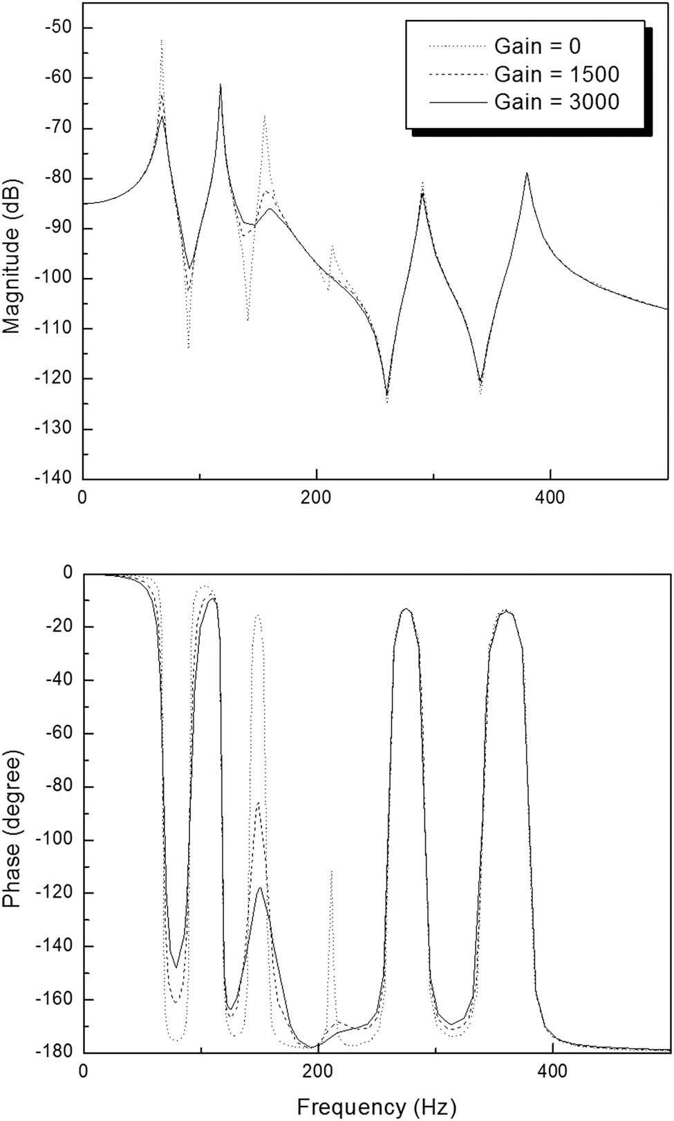
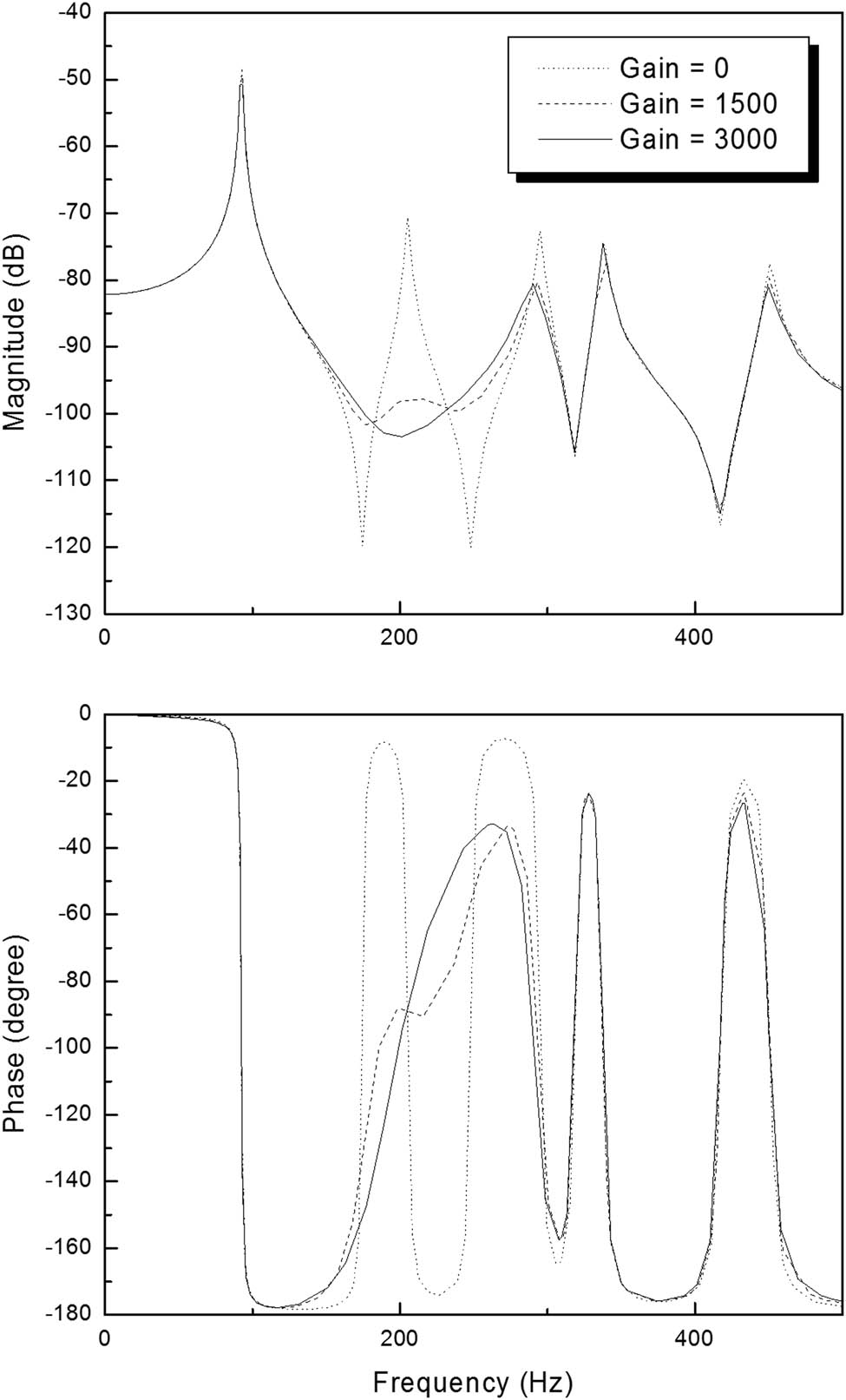
Frequency response of the shear-web case 1 due to a different feedback control gain.
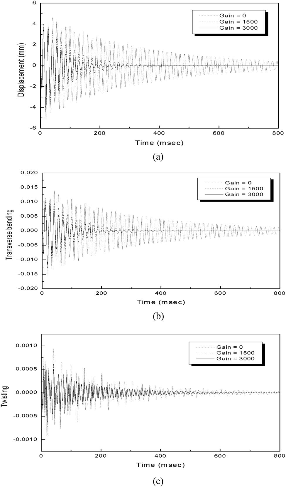
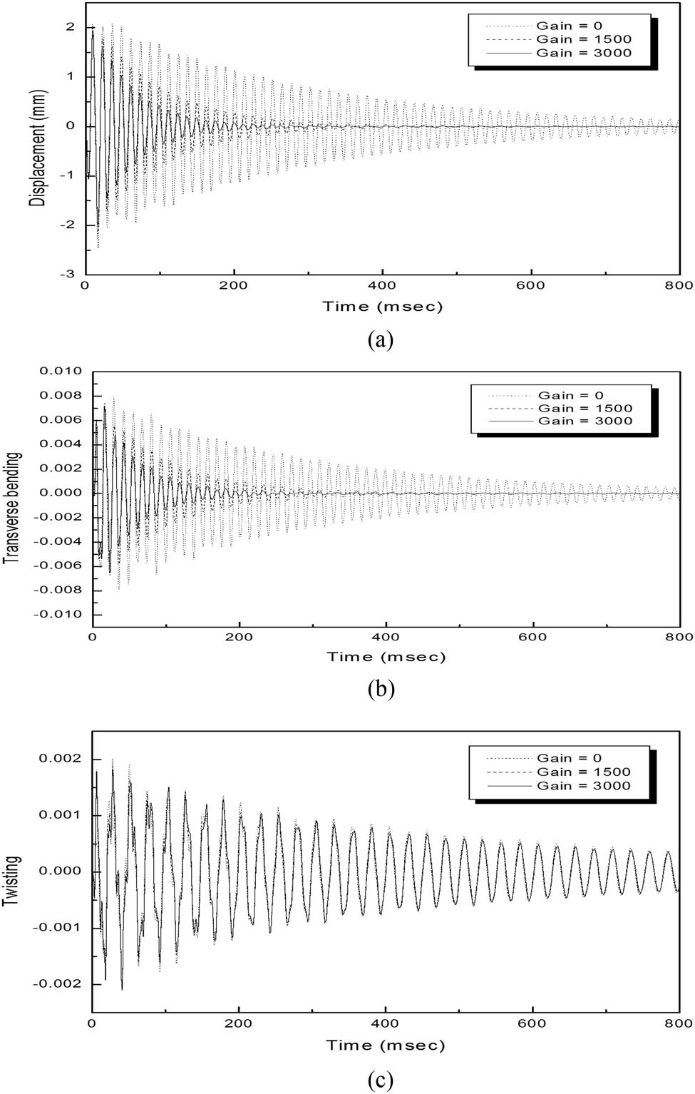
Responses of a stiffened plate (case 1) with various control gains: (a) vertical displacement, (b) transverse bending displacement and (c) lateral twisting displacement.
In the case of
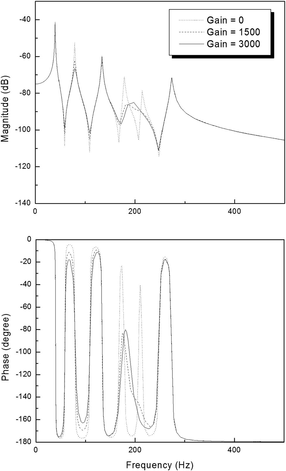
Frequency response of the shear-web case 2 due to a different feedback control gain.
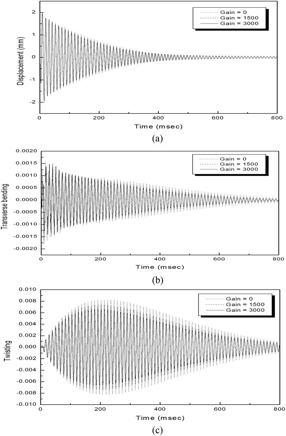
Responses of a stiffened plate (case 2) with various control gains: (a) vertical displacement, (b) transverse bending displacement and (c) lateral twisting displacement.
Frequency response of the shear-web case 3 due to a different feedback control gain.
Responses of a stiffened plate (case 3) with various control gains: (a) vertical displacement, (b) transverse bending displacement and (c) lateral twisting displacement.
As can be seen from Figures 9–14, the piezoelectric actuators can control the bending modes effectively; however, the control of the torsion modes is weak in the cases of all the stiffeners. This indicates that the vibration amplitude decays depend on the modal damping and the feedback control gain. According to equation (17), increasing the feedback control gains can result in a higher damping matrix in the system equation. Therefore, the vibration of a plate can be suppressed much faster at higher feedback control gains. It is important to optimize the control algorithm with the location of the shear web by considering the characteristics of the load direction applied to the wind turbine blades.
4 Conclusion
This article presents a transient response of a stiffened plate with the piezoelectric sensors and actuators subjected to external wind loads. The formulation is based on the first-order shear deformation theory of plate and beam. The constant negative velocity feedback control algorithm is used as a control scheme. The external wind load is assumed to be uniformly distributed on the plate surface. The numerical model is validated with theoretical and experimental data from the literature. In this study, the vibration characteristics and transient responses are compared with control algorithms and various shear-web locations.
When the piezoelectric patches are distributed over the entire surface of a plate, the effect of a shear-web location is investigated with three types of typical configurations. The shear-web locations have an effect on the stiffness of the stiffened plate. When the shear webs are placed between the centerline and the free edge, the stiffness of the stiffened plates is increased for a bending mode. However, the stiffness of a twisting mode is increased at free edges. Using a negative velocity feedback control algorithm, the control effect of a shear-web location at the middle of a plate (case 2) is weaker than those of others because of the increased stiffness due to the shear-web location. Moreover, the piezoelectric actuators can control the bending modes effectively; however, the control of the torsion modes is weak in all shear-web cases.
Therefore, optimizing the shear-web position and control algorithm according to the various load directions applied to the wind turbine blade is important. In the future, as an extension of the active vibration suppression method proposed in this article, an improved control algorithm will apply to the wind turbine blade for a load reduction.
-
Funding information: This work was supported by the Korea Institute of Energy Technology Evaluation and Planning (KETEP) and the Ministry of Trade, Industry & Energy (MOTIE) of the Republic of Korea (No. 20193010025800).
-
Conflict of interest: Author states no conflict of interest.
References
[1] Song ZG, Li FM. Active aeroelastic flutter analysis and vibration control of supersonic composite laminated plate. Comp Struct. 2012;94:702–13.10.1016/j.compstruct.2011.09.005Search in Google Scholar
[2] Qiao YH, Han J, Zhang CY, Chen J. Active vibration control of wind turbine blades by piezoelectric materials. Chin J Appl Mech. 2013;30(4):587–92.Search in Google Scholar
[3] Chandiramani NK. Active control of a piezo-composite rotating beam using coupled plant dynamics. J Sound Vib. 2010;329:2716–37.10.1016/j.jsv.2010.01.023Search in Google Scholar
[4] Li FM. Active aeroelastic flutter suppression of a supersonic plate with piezoelectric material. Int J Mech Sci. 2012;51:190–203.10.1016/j.ijengsci.2011.10.003Search in Google Scholar
[5] Kapuria S, Yasin MY. Active vibration suppression of multilayered plates integrated with piezoelectric fiber reinforced composites using an efficient finite element mode. J Sound Vib. 2010;329:3247–65.10.1016/j.jsv.2010.02.019Search in Google Scholar
[6] Phung PV, Lorenzis LD, Chien HT, Wahab MA. Analysis of laminated composite plates integrated with piezoelectric sensors and actuators using higher-order shear deformation theory and isogeometric finite elements. Comput Mater Sci. 2015;96:495–550.10.1016/j.commatsci.2014.04.068Search in Google Scholar
[7] Arefi M, Zenkour AM. Vibration and bending analysis of a sandwich microbeam with two integrated piezo-magnetic face-sheets. Comp Struct. 2017;159(1):479–90.10.1016/j.compstruct.2016.09.088Search in Google Scholar
[8] Arefi M, Zenkour AM. Size-dependent vibration and bending analyses of the piezomagnetic three-layer nanobeams. Appl Phys A. 2017;123:202.10.1007/s00339-017-0801-0Search in Google Scholar
[9] St-Amant Y, Cheng L. Simulations and experiments on active vibration control of a plate with integrated piezoceramics. Thin-Walled Struct. 2000;38(2):105–23.10.1016/S0263-8231(00)00034-3Search in Google Scholar
[10] Balamurugan V, Narayanan S. Shell finite element for smart piezoelectric composite plate/shell structures and its application to the study of active vibration control. Finite Elem Anal Des. 2001;37(9):713–38.10.1016/S0168-874X(00)00070-6Search in Google Scholar
[11] Mukherjee A, Joshi SP, Ganguli A. Active vibration control of piezolaminated stiffened plates. Comp Struct. 2002;55(4):435–43.10.1016/S0263-8223(01)00171-4Search in Google Scholar
[12] Sadek EA, Tawfik SA. A finite element model for the analysis of stiffened laminated plates. Comput Structure. 2000;75(4):369–83.10.1016/S0045-7949(99)00094-2Search in Google Scholar
[13] Song ZG, Li FM. Aerothermoelastic analysis and active flutter control of supersonic composite laminated cylindrical shells. Comp Struct. 2013;106:653–60.10.1016/j.compstruct.2013.07.029Search in Google Scholar
[14] Shen SH, Yang DQ. Nonlinear vibration of anisotropic laminated cylindrical shells with piezoelectric fiber reinforced composite actuators. Ocean Eng. 2014;80:36–49.10.1016/j.oceaneng.2014.01.016Search in Google Scholar
[15] Mirzaei MMH, Arefi M, Loghman A. Creep analysis of a rotating functionally graded simple blade: steady state analysis. Steel Comp Struct. 2019;33(3):463–72.Search in Google Scholar
[16] Mirzaei MMH, Arefi M, Loghman A. Thermoelastic analysis of a functionally graded simple blade using first-order shear deformation theory. Mech Adv Comp Structure. 2020;7(1):147–55.Search in Google Scholar
[17] Mirzaei MMH, Loghman A, Arefi M. Time-dependent creep analysis of a functionally graded beam with trapezoidal cross section using first-order shear deformation theory. Steel Comp Struct. 2019;30(6):567–76.10.1080/14484846.2019.1678994Search in Google Scholar
[18] Arefi M, Zenkour AM. Size-dependent electro-elastic analysis of a sandwich microbeam based on higher-order sinusoidal shear deformation theory and strain gradient theory. J Intell Mater Syst Struct. 2018;29(7):1394–1406.10.1177/1045389X17733333Search in Google Scholar
[19] Arefi M, Zenkour AM. Transient analysis of a three-layer microbeam subjected to electric potential. Int J Smart Nano Mater. 2017;8(1):20–40.10.1080/19475411.2017.1292967Search in Google Scholar
[20] Kiani Y. Torsional vibration of functionally graded carbon nanotube reinforced conical shells. Sci Eng Comp Mater. 2016;July 21:41–52.10.1515/secm-2015-0454Search in Google Scholar
[21] Jalaei MH, Civalek O. On dynamic instability of magnetically embedded viscoelastic porous FG nanobeam. Int J Eng Sci. 2019;143:14–32.10.1016/j.ijengsci.2019.06.013Search in Google Scholar
[22] Demir C, Civalek O. On the analysis of microbeams. Int J Eng Sci. 2017;121:14–33.10.1016/j.ijengsci.2017.08.016Search in Google Scholar
[23] Ebrahimi F, Barati MR, Civalek O. Application of Chebyshev-Ritz method for static stability and vibration analysis of nonlocal microstructure-dependent nanostructures. Eng Computers. 2020;36:953–64.10.1007/s00366-019-00742-zSearch in Google Scholar
[24] Liu T. Classical flutter and active control of wind turbine blade based on piezoelectric actuation. Shock Vib. 2015;2015:13. Article ID 292368, 13 pages.10.1155/2015/292368Search in Google Scholar
[25] Abdelrahman WG, Al-Garni AZ, Abdelmaksoud SI, Abdallah A. Effect of Piezoelectric Patch Size and Material on Active Vibration Control of Wind Turbine Blades. J Vib Eng Technol. 2018;6:155–61.10.1007/s42417-018-0020-9Search in Google Scholar
[26] Hulskamp AW, Wingerden JW, Barlas T, Champliaud H, van Kuik GAM, Bersee HEN, et al. Design of a scaled wind turbine with a smart rotor for dynamic load control experiments. Wind Energy. 2011;14:339–54.10.1002/we.424Search in Google Scholar
[27] Jacinto AC, Ambrosini RK, Danesi RF. Experimental and computational analysis of plates under air blast loading. Int J Impact Eng. 2001; 25(10):927–47.10.1016/S0734-743X(01)00031-8Search in Google Scholar
[28] Gupta AD, Gregory FH, Bitting RL, Bhattacharya S. Dynamic analysis of an explosively loaded hinged rectangular plate. Comput Struct. 1987;26(1–2):339–44.10.1016/0045-7949(87)90263-XSearch in Google Scholar
[29] Uchino K. “Future of ferroelectric devices”, ferroelectric devices. 2nd ed. Boca Raton: CRC Press; 2009. p. 297–338.10.1201/b15852-12Search in Google Scholar
[30] Lam KY, Peng XQ, Liu1 GR, Reddy JN. A finite-element model for piezoelectric composite laminates. Smart Mater Struct. 1997;6(5):583–91.10.1088/0964-1726/6/5/009Search in Google Scholar
[31] Mukherjee A. On finite element dynamic and stability analyses of stiffened plate structures. PhD Thesis. Kharagpur, India: Department of Naval Architecture, IIT Kharagpur; 1987.Search in Google Scholar
[32] Houlston R, Slater JE, Pegg N, Desrochers CG. On analysis of structural response of ship panels subjected to air blast loading. Comput Struct. 1985;21:273–89.10.1016/0045-7949(85)90250-0Search in Google Scholar
[33] Attaf B, Hollaway L. Vibrational analyses of stiffened and unstiffened composite plates subjected to in-plane loads. Composites. 1990;21(2):117–26.10.1016/0010-4361(90)90003-FSearch in Google Scholar
© 2021 Sang-Lae Lee, published by De Gruyter
This work is licensed under the Creative Commons Attribution 4.0 International License.
Articles in the same Issue
- Effects of Material Constructions on Supersonic Flutter Characteristics for Composite Rectangular Plates Reinforced with Carbon Nano-structures
- Processing of Hollow Glass Microspheres (HGM) filled Epoxy Syntactic Foam Composites with improved Structural Characteristics
- Investigation on the anti-penetration performance of the steel/nylon sandwich plate
- Flexural bearing capacity and failure mechanism of CFRP-aluminum laminate beam with double-channel cross-section
- In-Plane Permeability Measurement of Biaxial Woven Fabrics by 2D-Radial Flow Method
- Regular Articles
- Real time defect detection during composite layup via Tactile Shape Sensing
- Mechanical and durability properties of GFRP bars exposed to aggressive solution environments
- Cushioning energy absorption of paper corrugation tubes with regular polygonal cross-section under axial static compression
- An investigation on the degradation behaviors of Mg wires/PLA composite for bone fixation implants: influence of wire content and load mode
- Compressive bearing capacity and failure mechanism of CFRP–aluminum laminate column with single-channel cross section
- Self-Fibers Compacting Concrete Properties Reinforced with Propylene Fibers
- Study on the fabrication of in-situ TiB2/Al composite by electroslag melting
- Characterization and Comparison Research on Composite of Alluvial Clayey Soil Modified with Fine Aggregates of Construction Waste and Fly Ash
- Axial and lateral stiffness of spherical self-balancing fiber reinforced rubber pipes under internal pressure
- Influence of technical parameters on the structure of annular axis braided preforms
- Nano titanium oxide for modifying water physical property and acid-resistance of alluvial soil in Yangtze River estuary
- Modified Halpin–Tsai equation for predicting interfacial effect in water diffusion process
- Experimental research on effect of opening configuration and reinforcement method on buckling and strength analyses of spar web made of composite material
- Photoluminescence characteristics and energy transfer phenomena in Ce3+-doped YVO4 single crystal
- Influence of fiber type on mechanical properties of lightweight cement-based composites
- Mechanical and fracture properties of steel fiber-reinforced geopolymer concrete
- Handcrafted digital light processing apparatus for additively manufacturing oral-prosthesis targeted nano-ceramic resin composites
- 3D printing path planning algorithm for thin walled and complex devices
- Material-removing machining wastes as a filler of a polymer concrete (industrial chips as a filler of a polymer concrete)
- The electrochemical performance and modification mechanism of the corrosion inhibitor on concrete
- Evaluation of the applicability of different viscoelasticity constitutive models in bamboo scrimber short-term tensile creep property research
- Experimental and microstructure analysis of the penetration resistance of composite structures
- Ultrasensitive analysis of SW-BNNT with an extra attached mass
- Active vibration suppression of wind turbine blades integrated with piezoelectric sensors
- Delamination properties and in situ damage monitoring of z-pinned carbon fiber/epoxy composites
- Analysis of the influence of asymmetric geological conditions on stability of high arch dam
- Measurement and simulation validation of numerical model parameters of fresh concrete
- Tuning the through-thickness orientation of 1D nanocarbons to enhance the electrical conductivity and ILSS of hierarchical CFRP composites
- Performance improvements of a short glass fiber-reinforced PA66 composite
- Investigation on the acoustic properties of structural gradient 316L stainless steel hollow spheres composites
- Experimental studies on the dynamic viscoelastic properties of basalt fiber-reinforced asphalt mixtures
- Hot deformation behavior of nano-Al2O3-dispersion-strengthened Cu20W composite
- Synthesize and characterization of conductive nano silver/graphene oxide composites
- Analysis and optimization of mechanical properties of recycled concrete based on aggregate characteristics
- Synthesis and characterization of polyurethane–polysiloxane block copolymers modified by α,ω-hydroxyalkyl polysiloxanes with methacrylate side chain
- Buckling analysis of thin-walled metal liner of cylindrical composite overwrapped pressure vessels with depressions after autofrettage processing
- Use of polypropylene fibres to increase the resistance of reinforcement to chloride corrosion in concretes
- Oblique penetration mechanism of hybrid composite laminates
- Comparative study between dry and wet properties of thermoplastic PA6/PP novel matrix-based carbon fibre composites
- Experimental study on the low-velocity impact failure mechanism of foam core sandwich panels with shape memory alloy hybrid face-sheets
- Preparation, optical properties, and thermal stability of polyvinyl butyral composite films containing core (lanthanum hexaboride)–shell (titanium dioxide)-structured nanoparticles
- Research on the size effect of roughness on rock uniaxial compressive strength and characteristic strength
- Research on the mechanical model of cord-reinforced air spring with winding formation
- Experimental study on the influence of mixing time on concrete performance under different mixing modes
- A continuum damage model for fatigue life prediction of 2.5D woven composites
- Investigation of the influence of recyclate content on Poisson number of composites
- A hard-core soft-shell model for vibration condition of fresh concrete based on low water-cement ratio concrete
- Retraction
- Thermal and mechanical characteristics of cement nanocomposites
- Influence of class F fly ash and silica nano-micro powder on water permeability and thermal properties of high performance cementitious composites
- Effects of fly ash and cement content on rheological, mechanical, and transport properties of high-performance self-compacting concrete
- Erratum
- Inverse analysis of concrete meso-constitutive model parameters considering aggregate size effect
- Special Issue: MDA 2020
- Comparison of the shear behavior in graphite-epoxy composites evaluated by means of biaxial test and off-axis tension test
- Photosynthetic textile biocomposites: Using laboratory testing and digital fabrication to develop flexible living building materials
- Study of gypsum composites with fine solid aggregates at elevated temperatures
- Optimization for drilling process of metal-composite aeronautical structures
- Engineering of composite materials made of epoxy resins modified with recycled fine aggregate
- Evaluation of carbon fiber reinforced polymer – CFRP – machining by applying industrial robots
- Experimental and analytical study of bio-based epoxy composite materials for strengthening reinforced concrete structures
- Environmental effects on mode II fracture toughness of unidirectional E-glass/vinyl ester laminated composites
- Special Issue: NCM4EA
- Effect and mechanism of different excitation modes on the activities of the recycled brick micropowder