3D printing path planning algorithm for thin walled and complex devices
-
Min Yang
 ,
Menggang Lai
,
Menggang Lai

Abstract
With the popularity of stereo printing technology, 3D printers are widely used in industry, manufacturing, medicine, and other industries to quickly manufacture small devices. Before 3D printing, it is necessary to plan the printing path. Unreasonable printing path will not only increase the time consumption of printing products, but also cause printing failure due to the accumulation of stress and deformation in the printing process. In order to overcome the superimposed stress and deformation in the process of printing thin-walled complex devices, this article introduces the idea of balanced stress based on the basic damage of the path planning based on the potential field method. In the printing process, the ring path, island path and cross path are added to overcome the stress deformation phenomenon and improve the printing quality. Finally, the 3D printer is used to manufacture thin-walled complex devices, and the feasibility of the balanced potential field method is verified by physical comparison.
1 Introduction
3D printing technology, also known as a layered rapid prototyping technology, is a kind of technology based on the digital model file, which uses nylon glass fiber, gypsum material, aluminum material, and other powder metal or plastic and other adhesive materials to manufacture devices of arbitrary shape by slicing and accumulating. Compared with the traditional manufacturing industry, 3D printing technology is widely used in medical devices, aerospace, automobile manufacturing, and other fields because of its low-cost production mode, short cycle development time, and convenient and complex process, and even known as the subversive technology to promote the “third industrial revolution.” As shown in Figure 1, common 3D printing technologies mainly include stereolithography, fused deposition (FDM), selective laser sintering, and laser near net forming. No matter what technology is selected, it is necessary to plan a reasonable printing path before printing, to make the 3D printing process fast and accurate and to improve the printing efficiency and quality.

Common 3D printing technology.
To plan a reasonable printing path, researchers have conducted extensive research on 3D printing path planning to improve printing efficiency and molding quality. The planning methods of reciprocating linear scanning [1,2], which is a traditional way of 3D printing. Its technology is relatively mature and has the characteristics of fast speed and simple algorithm. However, planning in one direction will not only cause a lot of empty paths, but also lead to serious stress bending. In order to reduce the time-consuming of empty paths in printing and to improve the printing efficiency, Rui-Shi et al. [3] applied “Z” planning algorithm to print devices. To some extent, it can reduce the warpage of printing, but it cannot solve the problem of excessive burr at the inflection point. Literature [4,5,6] proposes two simple algorithms and plans the offset contour according to the model contour. In the process of printing, the path is planned step by step and layer by layer according to the object contour from outside to inside and from bottom to top. Although the printing time and the edge burr are reduced, it is only suitable for regular shapes with smooth boundary and simple structure. In the process of step-by-step printing inward, “fracture” phenomenon is more serious [7]. The above methods consider devices to be printed as a whole, which are not suitable for special devices with “island.” Xiao-ya and Zheng et al. [8,9,10] divided the “isolated island” in the object into sections by the method of type slicing to improve the printing quality. In addition, intelligent algorithms such as genetic algorithm, ant colony algorithm, hash algorithm and Hilbert curve method [11,12,13,14] are also applied to 3D printing to find new and efficient planning methods.
Although these algorithms improve the 3D printing performance to a certain extent, they are not suitable for the special case of thin-walled devices. In order to improve the efficiency of 3D printing, this article proposes a path planning method based on balanced potential field (BPF) algorithm. The reasonable printing path is quickly planned by using the balanced field method. Based on this the stress deformation is abstracted as a potential field function, and the stress is reduced by the method of BPF. Force deformation can not only effectively print thin-walled complex devices, but also greatly reduce the warping of edge area in printing process, and improve the success rate and quality of printing.
2 3D printing path planning based on BPF method
2.1 Potential field method
Extensive research on potential field methods has proved the effectiveness in path planning, but those research mainly focuses on robots and unmanned aerial vehicles [15,16].
The main idea of path planning using the potential field (PF) is to find the global potential field function. In the process of path planning, the path that has been traversed and the potential field target in the unknown path is constantly changed, so that the algorithm can completely traverse the global environment. The principle is that in the process of path planning, the target position is set to attract the next trend of the path, and the repulsion position is set to prevent the path. In the global process, the potential function
The gravity function
where
The gravitational potential field function
In path planning, the unexpected area is represented by repulsion function. Therefore, the repulsion function of calculation point
The repulsion potential field function
where
By superposing the repulsion functions of all calculation points in the repulsion region, the repulsion function
In path planning, based on completing the current path point, the gradient direction of the next step is the superposition direction of the gravitational gradient field and the repulsive gradient field:
If the printed path points and blank areas are set as repulsive points, and the unprinted path points are gravity points, the global path can be traversed by using the potential field method. Although the ergodic potential field method has great advantages in fast path planning, the application to 3D path planning is not much. Yu-jie [17] introduced the potential field method into the path planning, and finally determined the optimal traversal path through the fast traversal method. Xiao-lei et al. [18] combined the grid complete traversal with artificial potential field method, so that the planned path has better performance in practicability, rationality and real-time.
The potential field method has great potential in the path planning of 3D printing, but the disadvantages are also obvious [19]. In the printing process, only how to traverse the path quickly is considered, but the stress mutation in the printing process is ignored, for example, the edge is easy to warp and the joint is easy to deform. It is necessary to improve the PF method to improve the printing quality and success rate.
2.2 Balanced potential field method
2.2.1 Basic thought
The traditional potential field method only considers the optimization of the printing path but ignores the stress of special printing positions such as inflection point and thin-walled edge. As shown in Figure 2, a plane in the printing process is extracted, in which the black arrow represents the print path and the red arrow indicates the stress direction. At the edge of the device, due to the stress warping, the device is easy to deform, resulting in printing failure. Moreover, because only the potential field method is used to print step by step and line by line, the warping is more serious, even leading to the printing failure of the whole device.

Stress deformation diagram.
The main idea of the BPF method is to balance the sudden change of stress direction at the edge of the device and the stress superposition in the process of the device plane printing step by step. To eliminate this adverse effect, it is necessary to change the path direction in real-time according to the stress change trend in the printing process, as shown in Figure 3, to plan the circular path, cross path, and island path, so as to reduce the stress deformation effect.

Planning path to overcome stress deformation. (a) Circular path. (b) Cross path. (c) Island path.
2.2.2 Algorithm derivation
Before 3D printing, assuming that the global path of the printed device is a two-dimensional point set
where
The resultant force of potential field function
If there is
Define
For any printing path
where
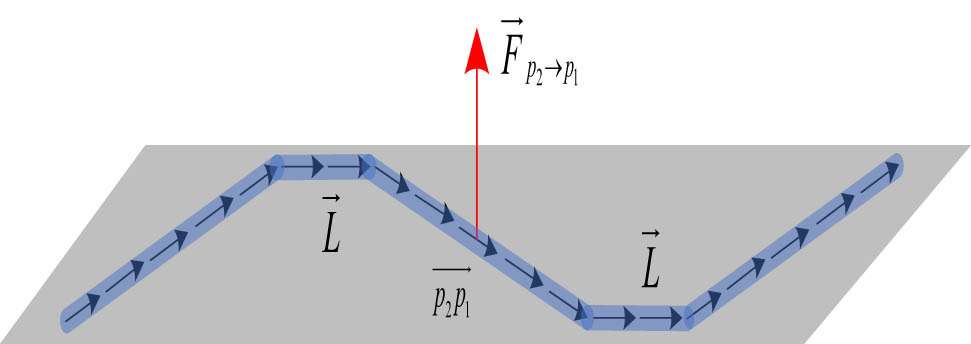
Force deformation diagram.
It can be concluded that the superimposed deformation force
If
Printing path based on balanced stress potential field
For a printing path
(14)where
Printing area based on balanced stress potential field
For a partial area of the device
(15)Then the stress superposition of the region
(16)When the superimposed stress of the region
(17)Printing thin-walled edge based on balanced stress potential field
For thin-walled complex devices, the stress balance method of edge is similar to print path. If

Connecting path of balanced force potential field at the edge of thin wall.
In other words, the path
The BPF method can be used in 3D printing for thin-walled complex devices based on three situations. By calculating the relative situation of superimposed stress and stress threshold, the superimposed stress effect can be cut off, and the printing quality and success rate can be improved.
3 Algorithm flow of 3D printing path planning based on balanced potential field method
Figure 6 is the algorithm flow chart of 3D printing path planning based on BPF method.

Algorithm flow of 3D printing path planning based on balanced potential field method.
After the algorithm starts to run, the parameters are initialized and their initial values are set, then the current print node is obtained. Based on the current print node, the next step print node is planned. According to the gravity function and repulsion function of the global node, the next optimal print node is obtained until all nodes of the device are traversed to generate the planned print path. At this time, the BPF method is introduced to determine whether there are paths and areas that may produce stress deformation in the generated path. According to different situations, the balanced printing path, balanced printing area and balanced thin-walled edge are used to balance all the stress within the threshold range and to improve the printing efficiency and success rate.
4 Comparative experiment and analysis
4.1 Configuration of 3D printing environment
Before comparing 3D printing, we need to configure the experimental environment. The 3D printer used and its printing consumables are shown in Figure 7. It can carry out secondary development for the self-developed planning program and printing path.

Arm-based 3D printer and consumables.
It adopts the printing principle of FDM and Cura slicing software to output designed model under the three-dimensional software ring as G-code for common path planning and 3D printing. If the path planned by the balanced potential field method is in G-code format and the point set part of the path planning is replaced, the absolute control of the nozzle can be carried out according to the designed path.
4.2 Experimental verification
For practical comparison, the general potential field (GPF) method and the balanced potential field method are used respectively for the 3D printing of thin-walled complex devices. For example, Figure 8(a) is the model of thin-walled complex devices planned by computer, and Figure 8(b) shows the equipment and devices.

3D printing model and devices in printing. (a) Thin-walled and complex device model. (b) Equipment and devices in printing process.
The devices printed by GPF and BPF are shown in Figure 9(a) and (b), respectively. The device printed by the GPF method has serious deformation. When printing thin-walled connections, the GPF method always prints in the same direction, it is easy to produce stress deformation, which makes the printed device partially deformed and difficult to meet the quality of high-precision printing. But the device printed based on BPF method can maintain the characteristics of the virtual model and overcome the stress effect.
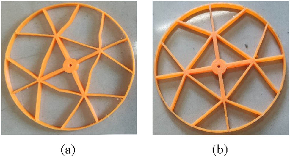
3D printing thin-walled complex device. (a) GPF method and (b) BPF method.
To make a more intuitive comparison between BPF and GPF, both algorithms for 3D printing are tested 10 times. From the formal operation of the 3D printing machine to the end of the device printing, the printing time and the quality of the printed device are recorded, respectively, and the results are shown in Figure 10. (The quality of the device is defined as the number of lines without stress deformation. The maximum number of line segments of the device is 32, so the best-printed quality of the device is 32.)

Result of two path planning algorithms.
The printing time of the GPF method is less than BPF, but the printing effect is not satisfactory. The GPF method can only print a small number of good line segments, moreover, it cannot control the printing quality, with large variance and many defective products. While the BPF method sacrifices a small part of printing time to exchange for printing quality, which not only improves the printing quality but also ensures that the stress deformation is reduced as much as possible in each 3D printing. The success rate of thin-walled complex devices is greatly improved.
5 Conclusion
This article first briefly introduces the path planning process of GPF, summarizes its advantages and disadvantages. Then GPF is improved to BPF, to balance the stress and deformation, which improves the strength of each print segment. Finally, actual devices are printed out by a 3D printer. Comparative experiments and analyses have proved the effectiveness of BPF method.
Although the possible extension of this work has great prospects, still there are several issues in need of further study.
In this article, a thin-walled device is printed, but the extension of BPF method to big prototypes needs more study.
Research on putting this work from theory to structural study needs further study.
-
Conflict of interest: Authors state no conflict of interest.
References
[1] Rajan VT, Srinivasan V, Tarabanis KA. The optimal zigzag direction for filling a two-dimensional region. Rapid Prototyp J. 2001;7(5):231–41.10.1108/13552540110410431Suche in Google Scholar
[2] Asiabanpour B, Khoshnevis B. Machine path generation for the SIS process. Robot Comput-Integ Manuf. 2004;20(3):167–75.10.1016/j.rcim.2003.10.005Suche in Google Scholar
[3] Rui-shi T, Ming-yao L, Fan Z, Yue-gang T. Continuous path planning algorithm for carbon fiber composite material 3D printing. Mach Des Manuf. 2019;6:1–4.Suche in Google Scholar
[4] Chang-biao H, Kai-yong J, Jun-yi L. Research on algorithm for contour lines offset and interference elimination. Mech Electr Eng Technol. 2007;36(10):75–7.Suche in Google Scholar
[5] Wen-jun X. Variable distance offset filling algorithm for Centroid contraction[D]. Wuhan: Huazhong University of Science and Technology; 2007.Suche in Google Scholar
[6] Zhong-wei L, Chang-biao H, Ze-hao W. Algorithm on generation of spiral filling path for planar con-tour. Comp Eng Appl. 2015;51(18):180–5.Suche in Google Scholar
[7] Serra T, Ortiz-Hernandez M, Engel E, Planell JA, Navarro M. Relevance of PEG in PLA-based blends for tissue engineering 3D-printed scaffolds. Mater Sci Eng. 2014;38(1):55–62.10.1016/j.msec.2014.01.003Suche in Google Scholar PubMed
[8] Xiao-ya Z, Fa-lai C. 3D printing path planning of fractal models. J Comput Des Comput Graph. 2018;30(06):1123–35.10.3724/SP.J.1089.2018.16618Suche in Google Scholar
[9] Zheng Y, Pan M, Chen F. Boundary correspondence of planar domains for isogeometric analysis based on optimal mass transport. Comput Aided Des. 2019;114:28–36.10.1016/j.cad.2019.04.008Suche in Google Scholar
[10] Yan-li T, Yong-qiang Z. Research on 3D image optimization and segmentation of 3D print geometry. Comput Simul. 2018;35(8):165–9.Suche in Google Scholar
[11] Xing-guo H, Xiao-hui S, Ming Y, Hai-jun C, Guo-fu Yin. Path optimization algorithm of 3D printing based on fused deposition modeling. Trans Chin Soc Agric Machinery. 2018;49(3):393–401.Suche in Google Scholar
[12] Yan-yan Z. Research on 3D printing path planning technology based on FDM Technology. Changchun: Changchun University of Technology; 2016.Suche in Google Scholar
[13] Li-gang L, Wen-peng X, Wei-ming W, Zhou-wang Y, Xiu-liu P. Survey on geometric computing in 3D printing. Chin J Comp. 2015;6:1243–67.Suche in Google Scholar
[14] Feng-ying C, Xiao-wei L. Research on 3D printing path planning. J Qingdao Univ Sci Technol (Nat Sci Ed). 2020;41(2):101–5.Suche in Google Scholar
[15] Liu S, Zhang Q, Zhou D. Obstacle avoidance path planning of space manipulator based on improved artificial potential field method. J Inst Eng (India): Ser C. 2014;95(1):31–9.10.1007/s40032-014-0099-zSuche in Google Scholar
[16] Ren J, McIsaac KA, Patel RV. Modified Newton’s method applied to potential field-based navigation for nonholonomic robots in dynamic environments. Robotica. 2008;26(1):285–94.10.1017/S026357470700389XSuche in Google Scholar
[17] Yu-jie C. Research on path planning method of RoboCup medium group soccer robot [D]. Changsha, Hunan, China: Changsha University of Technology; 2015.Suche in Google Scholar
[18] Xiao-lei L, Lin J, Zu-fei J, Chen G. Mobile robot path planning based on environment modeling of grid method in unstructured environment. Mach Tool Hydraul. 2016;44(17):1–7.Suche in Google Scholar
[19] Jia YL. Research on 3D printing path planning algorithms based on reinforcement learning. Dalian: Dalian University of Technology; 2019.Suche in Google Scholar
© 2021 Min Yang et al., published by De Gruyter
This work is licensed under the Creative Commons Attribution 4.0 International License.
Artikel in diesem Heft
- Effects of Material Constructions on Supersonic Flutter Characteristics for Composite Rectangular Plates Reinforced with Carbon Nano-structures
- Processing of Hollow Glass Microspheres (HGM) filled Epoxy Syntactic Foam Composites with improved Structural Characteristics
- Investigation on the anti-penetration performance of the steel/nylon sandwich plate
- Flexural bearing capacity and failure mechanism of CFRP-aluminum laminate beam with double-channel cross-section
- In-Plane Permeability Measurement of Biaxial Woven Fabrics by 2D-Radial Flow Method
- Regular Articles
- Real time defect detection during composite layup via Tactile Shape Sensing
- Mechanical and durability properties of GFRP bars exposed to aggressive solution environments
- Cushioning energy absorption of paper corrugation tubes with regular polygonal cross-section under axial static compression
- An investigation on the degradation behaviors of Mg wires/PLA composite for bone fixation implants: influence of wire content and load mode
- Compressive bearing capacity and failure mechanism of CFRP–aluminum laminate column with single-channel cross section
- Self-Fibers Compacting Concrete Properties Reinforced with Propylene Fibers
- Study on the fabrication of in-situ TiB2/Al composite by electroslag melting
- Characterization and Comparison Research on Composite of Alluvial Clayey Soil Modified with Fine Aggregates of Construction Waste and Fly Ash
- Axial and lateral stiffness of spherical self-balancing fiber reinforced rubber pipes under internal pressure
- Influence of technical parameters on the structure of annular axis braided preforms
- Nano titanium oxide for modifying water physical property and acid-resistance of alluvial soil in Yangtze River estuary
- Modified Halpin–Tsai equation for predicting interfacial effect in water diffusion process
- Experimental research on effect of opening configuration and reinforcement method on buckling and strength analyses of spar web made of composite material
- Photoluminescence characteristics and energy transfer phenomena in Ce3+-doped YVO4 single crystal
- Influence of fiber type on mechanical properties of lightweight cement-based composites
- Mechanical and fracture properties of steel fiber-reinforced geopolymer concrete
- Handcrafted digital light processing apparatus for additively manufacturing oral-prosthesis targeted nano-ceramic resin composites
- 3D printing path planning algorithm for thin walled and complex devices
- Material-removing machining wastes as a filler of a polymer concrete (industrial chips as a filler of a polymer concrete)
- The electrochemical performance and modification mechanism of the corrosion inhibitor on concrete
- Evaluation of the applicability of different viscoelasticity constitutive models in bamboo scrimber short-term tensile creep property research
- Experimental and microstructure analysis of the penetration resistance of composite structures
- Ultrasensitive analysis of SW-BNNT with an extra attached mass
- Active vibration suppression of wind turbine blades integrated with piezoelectric sensors
- Delamination properties and in situ damage monitoring of z-pinned carbon fiber/epoxy composites
- Analysis of the influence of asymmetric geological conditions on stability of high arch dam
- Measurement and simulation validation of numerical model parameters of fresh concrete
- Tuning the through-thickness orientation of 1D nanocarbons to enhance the electrical conductivity and ILSS of hierarchical CFRP composites
- Performance improvements of a short glass fiber-reinforced PA66 composite
- Investigation on the acoustic properties of structural gradient 316L stainless steel hollow spheres composites
- Experimental studies on the dynamic viscoelastic properties of basalt fiber-reinforced asphalt mixtures
- Hot deformation behavior of nano-Al2O3-dispersion-strengthened Cu20W composite
- Synthesize and characterization of conductive nano silver/graphene oxide composites
- Analysis and optimization of mechanical properties of recycled concrete based on aggregate characteristics
- Synthesis and characterization of polyurethane–polysiloxane block copolymers modified by α,ω-hydroxyalkyl polysiloxanes with methacrylate side chain
- Buckling analysis of thin-walled metal liner of cylindrical composite overwrapped pressure vessels with depressions after autofrettage processing
- Use of polypropylene fibres to increase the resistance of reinforcement to chloride corrosion in concretes
- Oblique penetration mechanism of hybrid composite laminates
- Comparative study between dry and wet properties of thermoplastic PA6/PP novel matrix-based carbon fibre composites
- Experimental study on the low-velocity impact failure mechanism of foam core sandwich panels with shape memory alloy hybrid face-sheets
- Preparation, optical properties, and thermal stability of polyvinyl butyral composite films containing core (lanthanum hexaboride)–shell (titanium dioxide)-structured nanoparticles
- Research on the size effect of roughness on rock uniaxial compressive strength and characteristic strength
- Research on the mechanical model of cord-reinforced air spring with winding formation
- Experimental study on the influence of mixing time on concrete performance under different mixing modes
- A continuum damage model for fatigue life prediction of 2.5D woven composites
- Investigation of the influence of recyclate content on Poisson number of composites
- A hard-core soft-shell model for vibration condition of fresh concrete based on low water-cement ratio concrete
- Retraction
- Thermal and mechanical characteristics of cement nanocomposites
- Influence of class F fly ash and silica nano-micro powder on water permeability and thermal properties of high performance cementitious composites
- Effects of fly ash and cement content on rheological, mechanical, and transport properties of high-performance self-compacting concrete
- Erratum
- Inverse analysis of concrete meso-constitutive model parameters considering aggregate size effect
- Special Issue: MDA 2020
- Comparison of the shear behavior in graphite-epoxy composites evaluated by means of biaxial test and off-axis tension test
- Photosynthetic textile biocomposites: Using laboratory testing and digital fabrication to develop flexible living building materials
- Study of gypsum composites with fine solid aggregates at elevated temperatures
- Optimization for drilling process of metal-composite aeronautical structures
- Engineering of composite materials made of epoxy resins modified with recycled fine aggregate
- Evaluation of carbon fiber reinforced polymer – CFRP – machining by applying industrial robots
- Experimental and analytical study of bio-based epoxy composite materials for strengthening reinforced concrete structures
- Environmental effects on mode II fracture toughness of unidirectional E-glass/vinyl ester laminated composites
- Special Issue: NCM4EA
- Effect and mechanism of different excitation modes on the activities of the recycled brick micropowder